Project 1
The challenge is to create wire harness on the engine. Engine 3D is provided along with connectors and channel.
I down load all the provided data in a new folder and name the folder Project1.
I open CATIA and open the engine stp file and save this as catpart.
Next I create a product file and name it “Project1 Engine harness” and save this file in the same folder. Then I add a new product file in the product file for wire harness creation and name it “Engine Wire harness Geometrical Bundle”
Next, I copy the received engine model file in product file project1 engine harness.
So now I have two product files in my Project1 Engine Harness file. One is Engine wire harness geometrical Bundle and second is received Engine surface.
I Open the product file Engine wire harness Geometrical Bundle to add the connectors required. Normally a study must be made regarding the connectors required. Type of connectors and number of each connector. For this I create a table. I arrive at the below table showing the connector requirements.
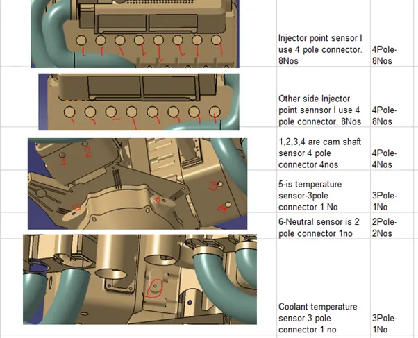
I first located the part file for 2pin, 3pin, 4pin connector and copied them in the working assembly folder. Opened each part and checked if the connector is electrically defined and also checked for the connecting and bundle entry points defined or not. Those which was not defined I created all the points and defined it electrically saved. Next, I copied all the three connectors in the “Engine Wire Harness Geometrical Bundle” product file which was already created. Next I start working on placing of all the connector by copying multiple times in geometrical bundle as required and start placing each connector to the nearest point of connection by using the snap-smartmove command in mechanical assemlby environment. I position all the 2pin connector 2nos, 3 pon connector 2nos, 4 piin connector 16nos in their respective position.
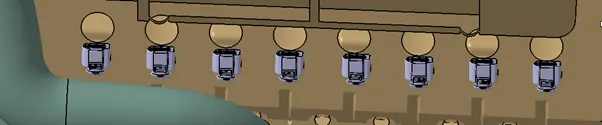

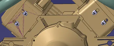
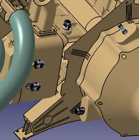
All the connectors are positioned and now I have to plan the wire harness routing.
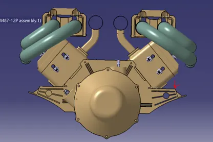
To start routing I assume from the above engine on chassis picture, Wire enters from the right side marked red. So, this entered wire has to be first connected to a Inter connection connector. I choose a 12 pin connector for this C-776438. This is a wire to wire connector but is provided with provision for mounting clamps. I select firtree mounting for this connector from the Te.com website with is rotation lock facility. First the connector is defined with connector entry point, bundle entry point and cavity-clamping mounting point. Then this is defined as electrical connector and all the points bundle entry and connector connecting point are also defined as electrically.
Next I add a L bracket for placing Inter connection connector. I decided the L bracket as I could not find a suitable position and directly mounting on the engine surface is also not correct. The bracked with D shape opening in the bracket will assure that the bracket does not rotate and two holes on the bracket for fixing of the connector clamp with the clip as seen below.
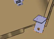
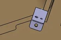
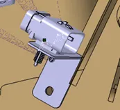
This is the main wiring connector and the routing on the engine area will start from this connector.
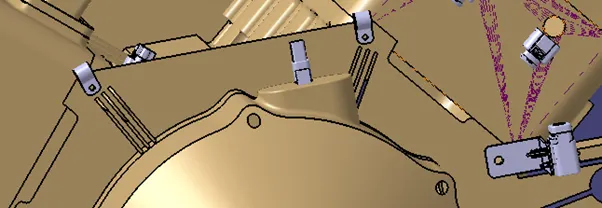
Next to route the wires I plan some clamps for holding the wires. I select Plastic clamp. First the wire from outside gets connected to the Inter connection connector and then extend to other connector on the engine. So to hold the wires tightly clamps at regular intervals to be given so I use screw type clamp. This clamp is selected because this can be positioned at the hole where a screw gets fit. Next I plan a plastic channel near the 8 injection connectors as exhaust pipe passes near by and so heat dissipation from the pipe has to be restricted by affecting the wire harness. One more advantage of using plastic channel is for neatly placing the wiring harness in a closed area instead of scattering in this area as many wire gets terminated to the connector. If a plastic channel is used there will be do direct heat transmission to the wires harness from exhaust pipe. One each channels on right side and left side is places as seen in the picture near to the 8nos injection sensor for routing of the wires.
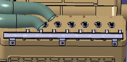
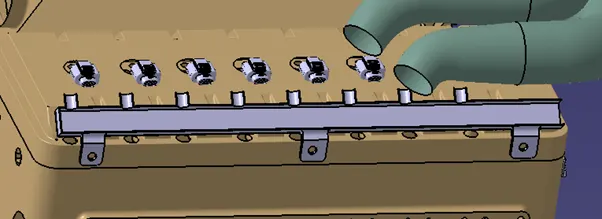
The channel is opened in part environment and bundle entry points and curve for passing bundle in the channel is created. This channel is then defined as an electrical part by selecting Define Equipment. After defining the channel as equipment, then the bundle entry points are designated. Two channels RH and LH channel are created. This channel is now copied in the assembly and then placed at the position shown. This now necessitates the clamping hole provision which is to be communicated to the concerned. Three holes each side. After feed back from the concerned the channel will be finalized or it will be modified accordingly. Next is harness routing.
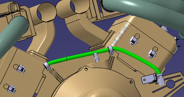
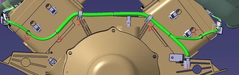
The wire is first started from interconnection connector (1 in pic below) with 15mm diameter wire harnessing.This 15mm wire is now passed through the plastic clamp marked 2 and then through plastic clamp marked 3 and then again to Firr tree clip fixed at point 4 which necciates a hole for fixing the firtree clip.From this point the wire harness is reduced to 10mm diameter as the next branch connects all the 8 injection sensor connectors. A firrtree clip is positioned at point 5 shown in picture and from there to the channel. Similarly on the other side a branch is created at a appropriate point and a 10mm diameter branch is drawn to connect the right side channel. A firtree clip is used a point 6 marked.
After this 10mm diameter wire harness is extended up to the end of the channel both sides. In the channel the routing is done by using extrenal curve reference and then the branchable points are created and branch routing is done between the connector through the channel outlet with main branch using 5mm wire harnessing.
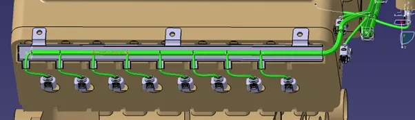
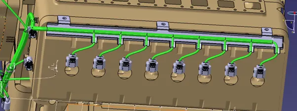
The above picture shows both side connectors harness branching done with main branch through the channel..
Next the cam position sensor to be connected with the main branch and for this I use firtree clip as the positions shown above and 5mm branches are created from the main branch to the connector.
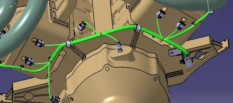
The below picture shows the channel closed with top cover and this makes the wire harness safe inside the channel from dust and heat. The wire harness outside channel will be covered with cot tube and insulation.
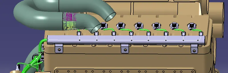
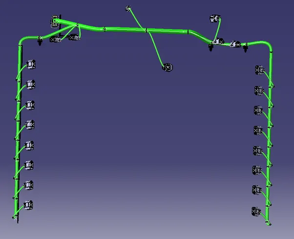
The total wire harness looks as below and I also do continuity check for this wiring and the report picture for false condition is shown below.
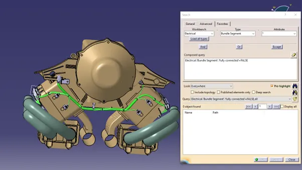
When the continuity is checked with false condition, no branch is detected for non continuity. This confirms all the branches are electrically connected and the contunity is clearly established.
I apply insulation on the exposed wires and then add cot tubes on this. The below picture shows the insulation applied to open harness wire bundles. I prefer cotton insulation tape for heat resistance.
In the wire harnessing and the connector position water flow into the connector cannot be considered as all the connector are fixed. Only water proof and dust proof connectors has tobe used.
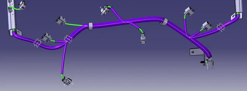
Next is flattening of the wire harness.
For flatenning I opened a new catia product file and opened "Electrical Harness Flatenning" environment. First I selected the option Harness Flatenning parameters. Here Standard parameters was set. The electrical connector was set at 3D. Next I opened the file "Project1 Engine harness" file. Both these file was tiled vertical and in the electrical harness flatenning file I select the command extract and select the file from the other assembly from the tiled window, file Engine Wire harness geometrical bundle. This extracts all the electrical wire harness bundle and the related electrical connector, firrclip, channels in the flatenning product file. The product file extracted will have and extension _Ehf
Once I flatennen the wire harness bundle, the bundle assembly looks as seen below. The wiring is flat but connectors are in rotated position, one of the last wire to the connector in the channel is changed in direction and projecting out of the channel end. This needs recification.
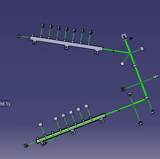
I rotated all the connectors and firtree clips to one ref planes. One of the branch rotated 180deg could not be edited. The end branch in the channel is seen projecting from channel.
Below is the drawing of the project1 flatenning.
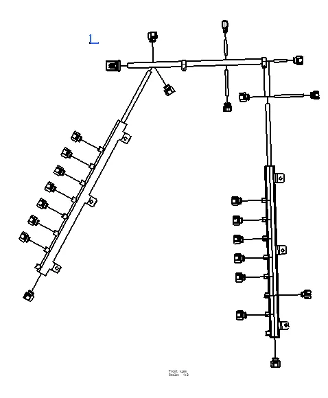
This completes the project1.
The folder of project1 with all related files is attached in zip condition