Fender Design
Challenge is to design a Fender from given skin data.
Input received
Skin of the fender
master section of drip Area
The challenge is to design Front fender mounting on the car.
The provisions are
Body side clamping, Pillar side clamping, Sill side clamping and Drip area clamping, Bumper side clamping. Also provide clamping provision of baffle on fender.
Started the challenge in NX.
Skin outside area is untouched.
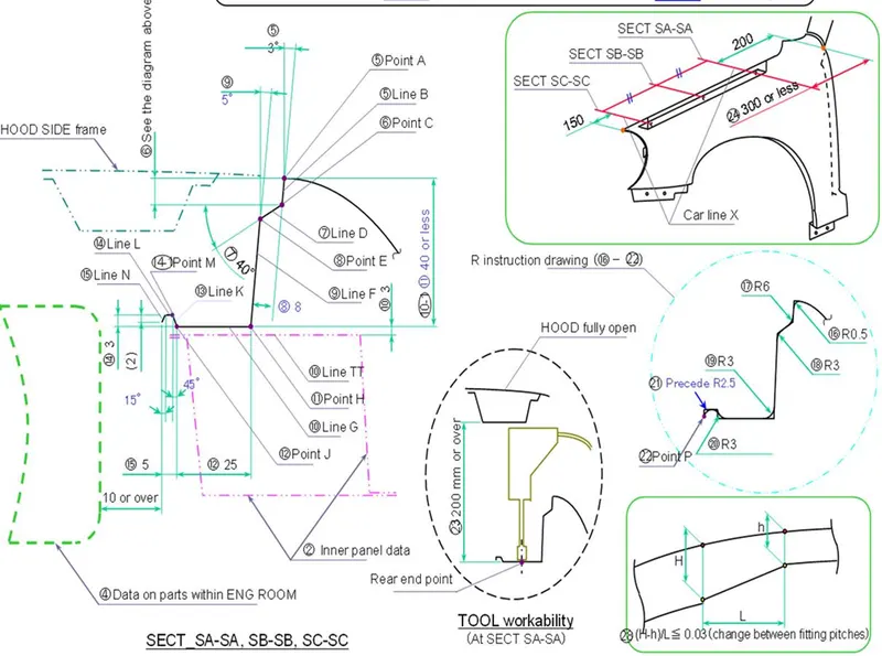
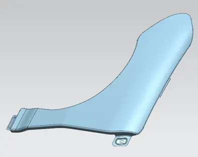
First opened the the given fender skin data, started with offset top curve by 7mm on the surface and started the drip area first. The drip area is 200mm from cowl part area and 150mm from head light side. Create a plane from cowl part side at 200mm from the end part and one more plane from head lignt side at off set of 150mm (picture below) . Created intersection curve on the surface and started trimming the edges, Onece the drip area length was established after trimming, started creating the surfaces according to master section with law of extrusion command. 2D cad profile was created for geting the final bend of stiffener of the drip area as per the master section and the diagnol distances was considered for creating the surfaces. The finished drip area pictures stage wise attached below. Further with curve on surface different curves were created and skin surface was trimmed and with law of extension the surfaces for clamping area were created. Embosing surfaces were in the screw fitting area with flat faces. Dart was provided on drip area for strengthening. See picture below.
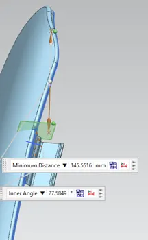 plane from head light side 150mm for drip area construction.
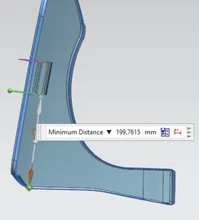 plane 200mm form cowl part area for drip area construction
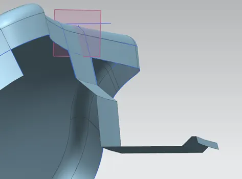
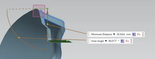
drip area surface creation using law extension with reference to master section.
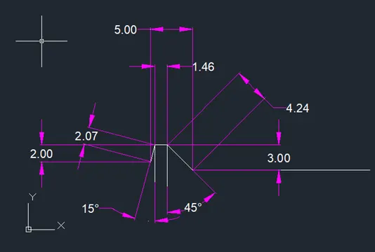
created dimensions for the diagnol distance of master section in 2D CAD
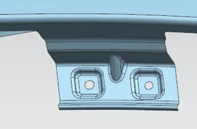
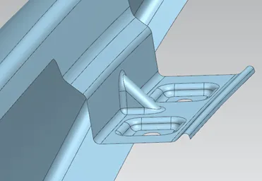
Completed pictures of Drip area clamping of fender
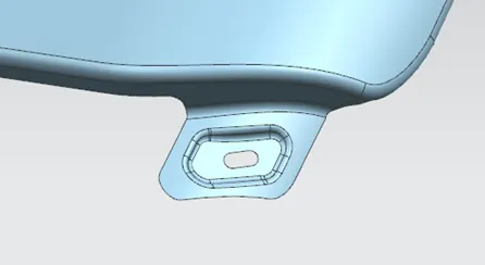
Provision for fixing fender at Body mounting area
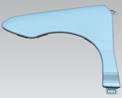
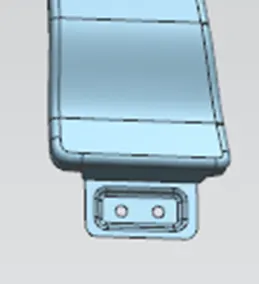
Provision for fixing fender at Sill area side
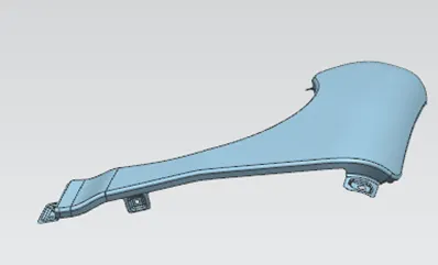
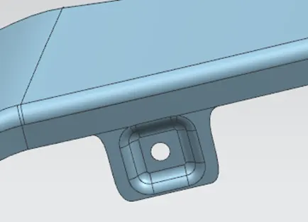
Pillar side fender clampin provision
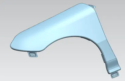
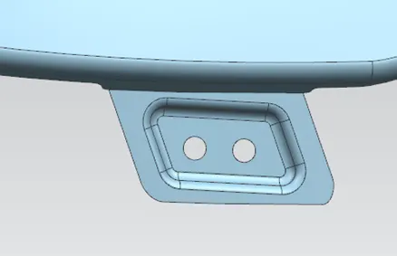
Bumper side clamping provision for fender
These are the fender clamping provisions provided.
Below you find the baffle fixing provision in the fender
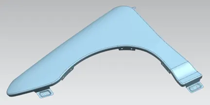
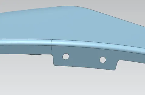
After all these the surface was thickened by 0.75mm and the part model completed
Further regarding the points followed in designing the fender is mainly the master section of Drip area clamping. The surface is to be generated as per the details in mastersection. The height of drip area must not exceed 40mm as shown as exceeding 40mm will lead in manufacturing issues of the sheet part. Normal draw components up 40mm in this region is found feasable. To give strength the end of the drip area has a u type reinforcement bend which is as per master section. A dart is provided in between for providing strength of drip area. Two embosing and two holes for screw clamping with a flat land around the hole is provided up to 10mm diameter.All hole size is considered 5mm in diameter and seating flat area of minimum 10mm in diameter is also considered. The embosing area is flat.
The sketches for embosing and hole on the planes are constrained and projected on the surface.
Edge blending of all sharp intersection is followed. sharp corner and edges of sheet is trimmed with corner radius.
Finally three areas where the sheet is bend perpendicular is provided corner relief for bend relief.
Baffle holding on fender only the skin was trimmed and holes for fixing baffle was provided.
From Tooling side the important points is draw depth not to exceed 40mm in drip clamp area, provide all bend and embosing corners with radius for sheet to flow and form, holes to be perpendicular to the surfaces or the direction of punching.
The part file is attached