Week 11 - Final project
Challenge is to create all the 4 skins given (A surfaces) into solid parts by creating B and C surface and assemble by interlocking each solid part to one another by using heat stakes on one part and flanges on adjacent part with holes for locking with heat stakes. The 4 parts which we are creating is only part of the car door inner cover. These platic parts are interlocked to each other by Flange and heat stakes and this sub assembly is fit on another sub assembly, the sheet metal assembly of car door by means of push pin lock. So in the B side features we are supposed to create maximum number of heat stakes for interlocking the plastic component, two or three locators for locating this plastic part sub assembly on the sheet metal sub assembly, pushpin provisions for locking sheet metal assembly with plastic sub assembly.
Push pin is a seperate plastic part used for quick lock between sub assemblies. This a circular and conical plastic part as shown in the picture. Push pins are pins which held in the plastic part by colar and conical locking area gets locked in a hole of sheet metal when pushed.
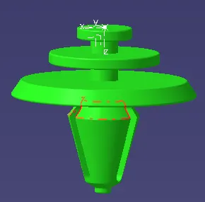
Received 4 Skin surface in assembled state and push pin part
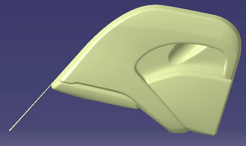
First inspected all the 4 master skin surface for quality and studied the master section given along with the surfaces. Created Product file and created four diffent part files in the assembly and copied the skin and master section in to the individual part files. Next created a tooling axis and started offsetting received skin A surface as per the thickness in master section and started to create B and C surface.
Basically there are 4 parts to make only half or a portion of Door cover. The skin provided belongs to Right hand door and the 4 parts created is named as bellow. (All the name given to the part are imaginary based on the use of the part in the car)
1. Lower substrate
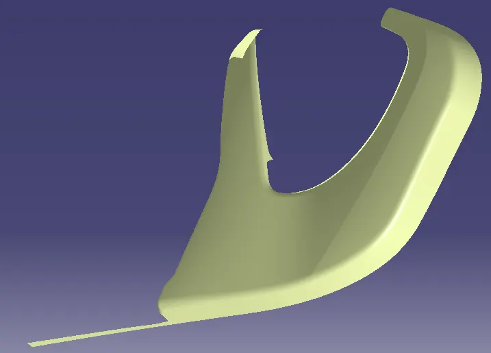
2. Arm rest.
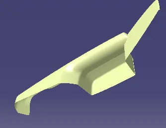
3. Bottle holder
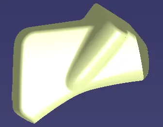
4.Lower Map pocket.
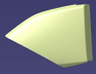
Below we look into creation of B- C surfaces and creation of solid part from closed surface.
1.Lower substrate.
Lower substrate part is main part which lock or binds other parts to this to form a sub assembly or it can be stated that other parts like arm rest, bottle holder and map pocket are mounted on the lower substrate to form a sub assembly.
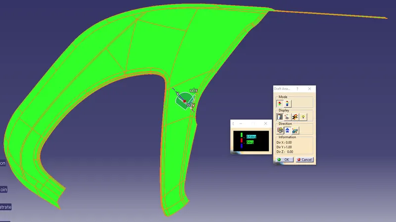
Creation of Tooling axis and cross verifing the tooling axis for draft analysis. To create a tooling axis in this part a surface is extracted and a centre point on this surface is created. A line is created with reference to point and direction is one of the global axis. In all the four parts the direction of tooling is point and global plane or axis is followed. This is because the heat stake of one part has to enter the holes of the flanges of other part, then different tooling axis will create features in different directions and this will end up in assembly problems.
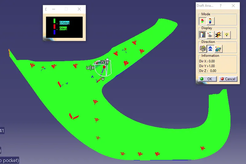
Below the tooling axis for this component is ok showing all the surface green even at 0.5deg.
Next created the B surface by offsetting the A surface by 2.5mm as per master section.
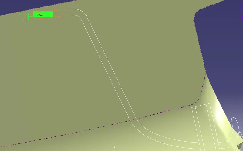
After B surface created C and joined all the three to form Closed surface and created Closed part as seen below.
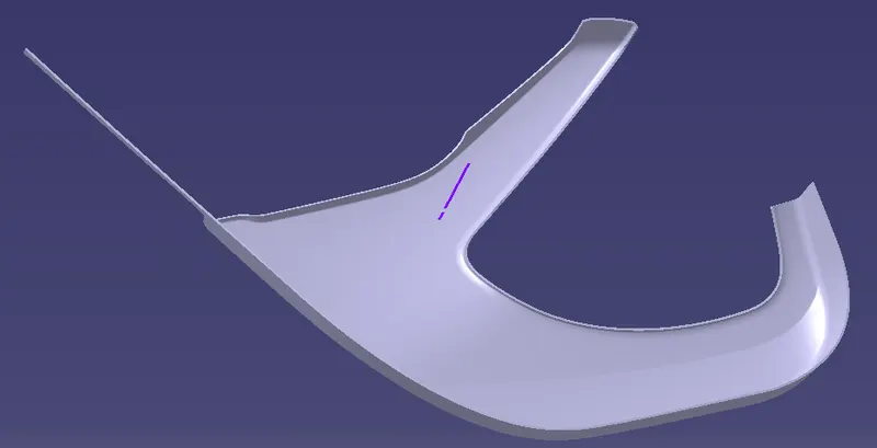
2.Arm Rest
This part takes the load of a passenger arm inside of the car. He keeps his arm on this part while seating or travelling in a car.
Here in the master section 3 lines are shown. The outer most surface given to us is the surface of leather or PU of thickness 2mm and after that is the wall thickness of 2.5mm which is the plastic part.
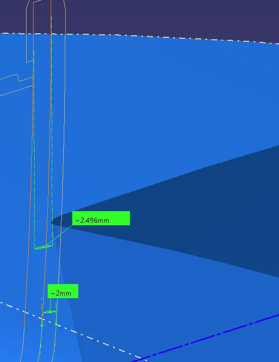
By offsetting the given surface to 2mm a new A surface was created. All the surface errors and patches was corrected and then B surface created by offsetting 2.5mm from the new A surface.
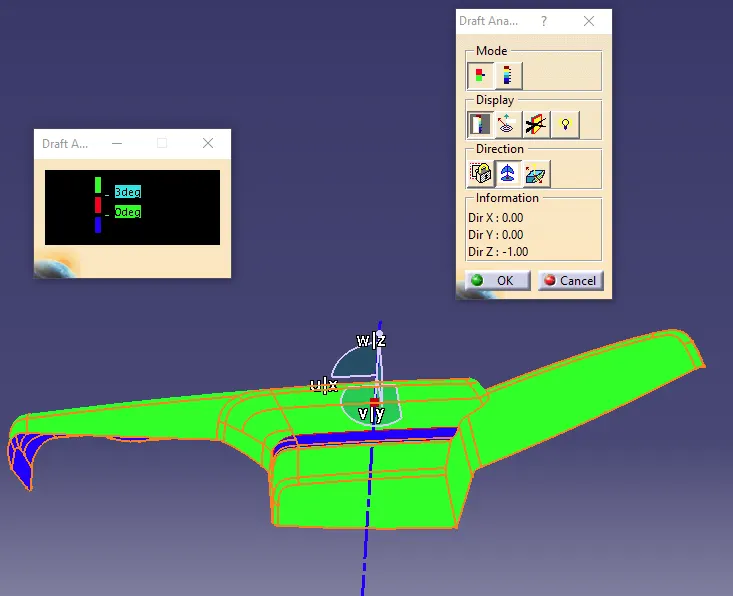
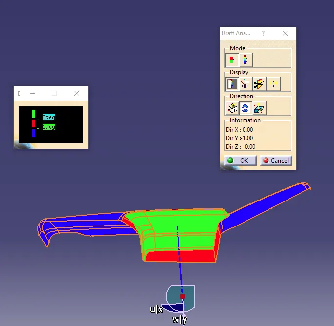
Tooling Axis 1 created but this part requires side cores and so require multiple tooling axis. In the picture below the draft analysis of the surface with respect to Basic tooling axis is shown. We find lot of blue surfaces which requires side cores. (This part as it is cannot be produced by plastic injection molding because molding tool which is core and cavity cannot open even by providing side core design. This part has to be re-designed or split.)
Picture of draft analysis with normal tooling axis.
Draft analysis with side tooling axis.
Next is the creation of B and C surface from the new 2mm offset A surface. There were some surface loss and errors which was corrected and a complete surface was created. A solid part from the closed surface was created as seen below.
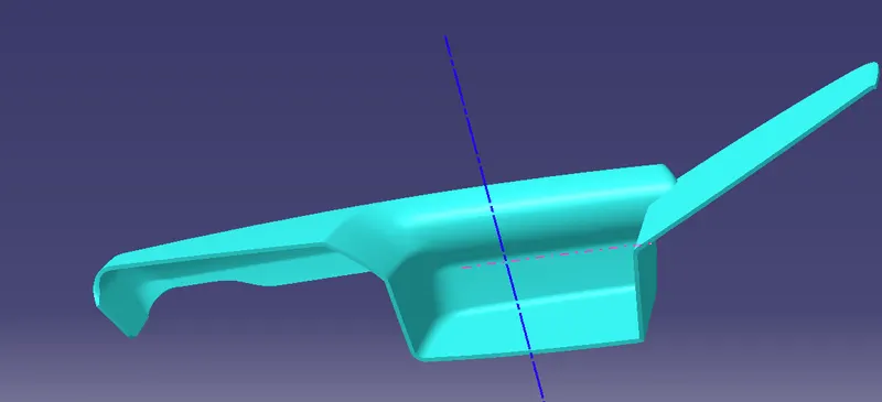
Picture below is outer skin surface received in blue and 2.5mm thick part below is created.
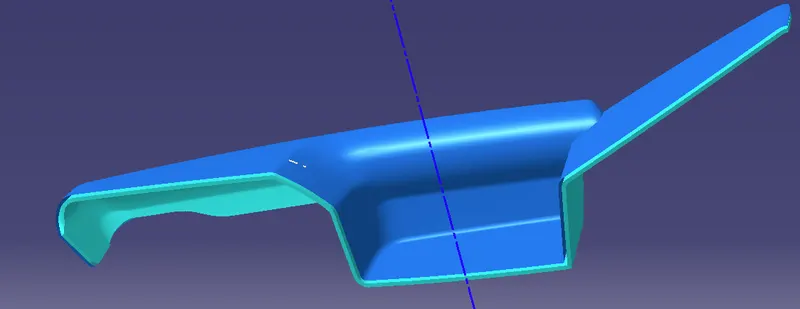
Next
3.Bottle holder
A surface checked and found Okay and proceeded to generate tooling axis.
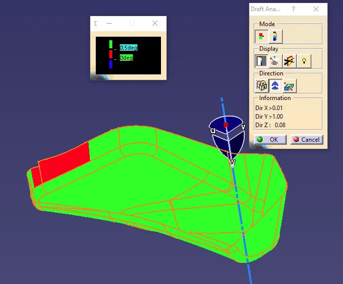
This tooling axis created with reference to compass angle changing and not with reference to any global axis or plane. With this reference draft analysis is cleared but it will be very difficult in creating B side features by extrude or pad command. Even with this tooling axis complete surface is not clearing draft analysis.
A new tooling axis was created considering in mind the B side features creation. Picture below shows the side surface which require some correction.
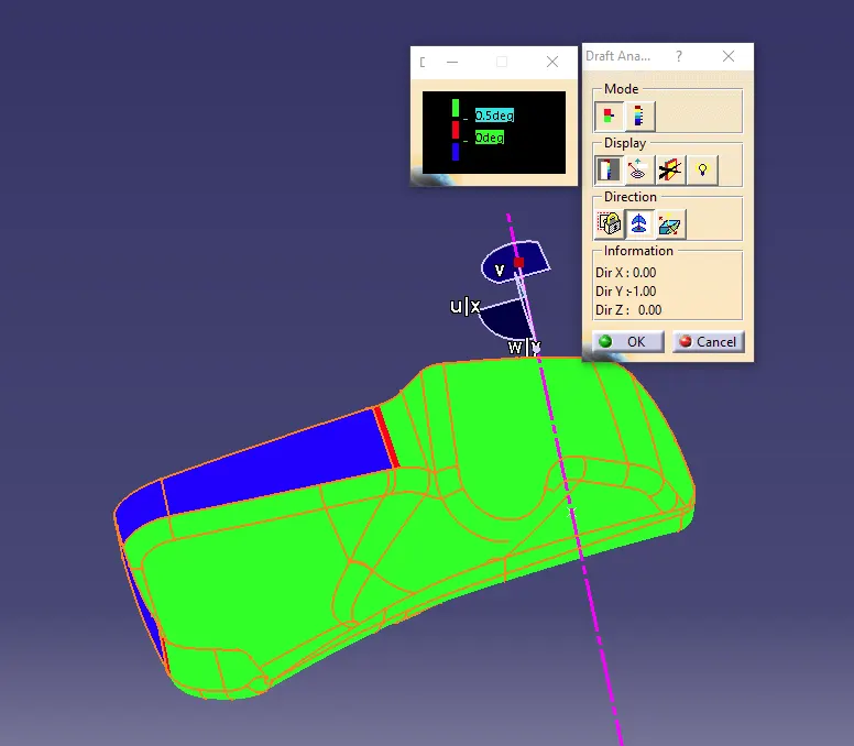
A thickness of 2.5mm is considered as there no seperate master section for this part. By seeing the mastersection of all other parts the thickness is 2.5mm so the same thickenss is considered for this part.
Next is the creation of B -C surface and closed surface. Below is the closed part created from closed surface.
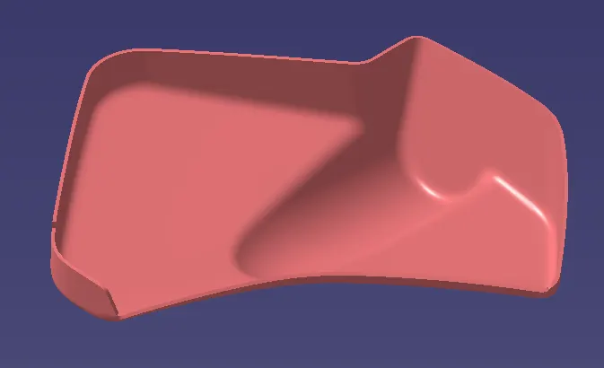
Next
4.Map pocket
Creation of tooling axis and checking. For creation a surface was extracted and a centre point created. A vertical line from the point was created with reference to global plane. The draft analysis is cross checked with reference to this axis. The result is as below.
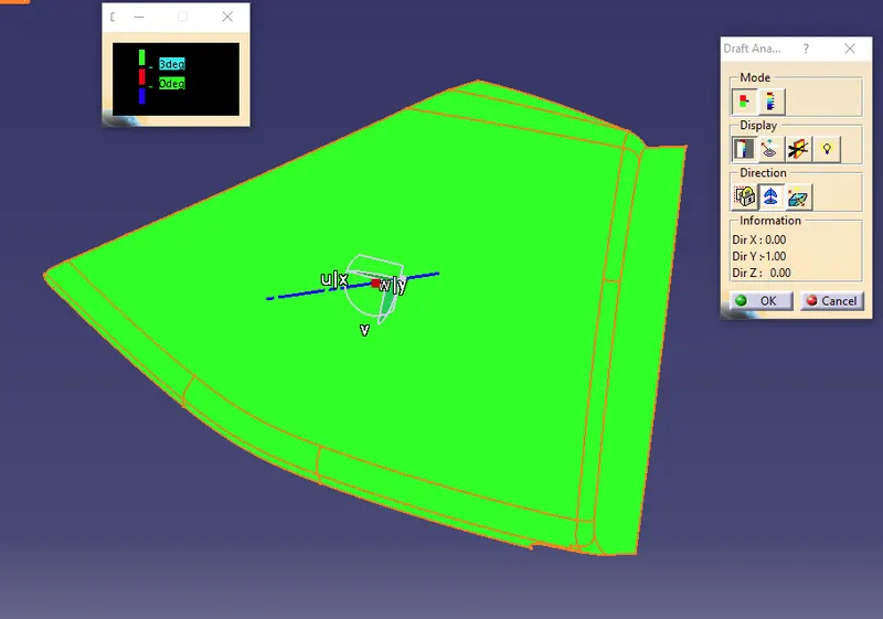
Next as per the master section the thickness is 2.5mm as seen below B surface is offset and created.
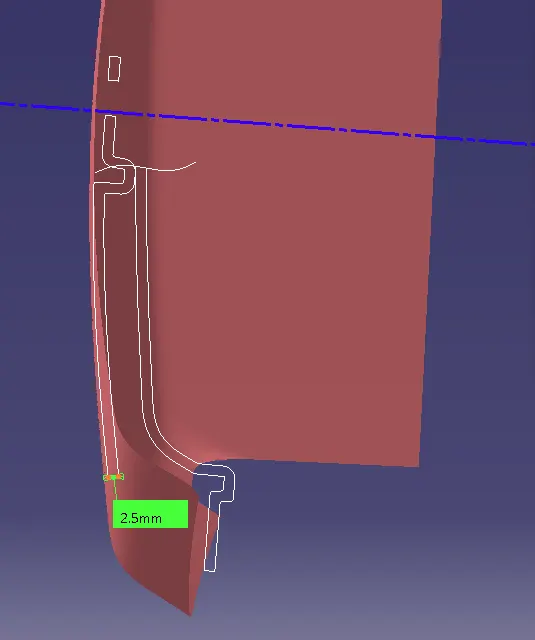
The surface was offset for 2.5mm for creation of B surface and the error in surface was corrected a after creating C surface and joining ABC a closed surface was created. Then a closed body generated from this closed surface.
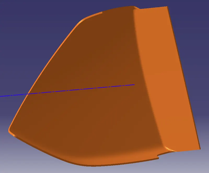
With this creation of tooling axis for all the four parts is complete and creation of solid completed. Next is B side features creation.
All four solid parts in the below picture
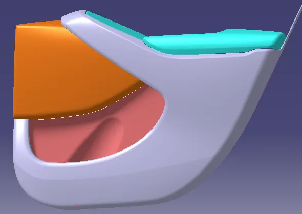
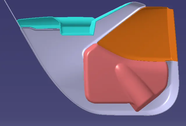
Next is B side features. As explained above the lower substrate is the main part on to which we will be fixing other parts. In the master section of lower substrate as seen below we have to provide heat stakes.
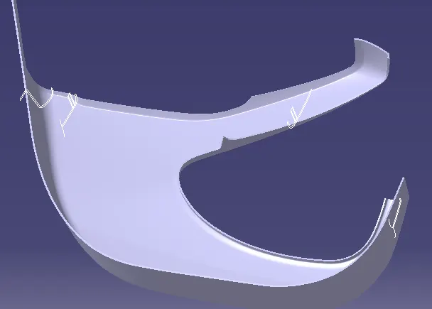
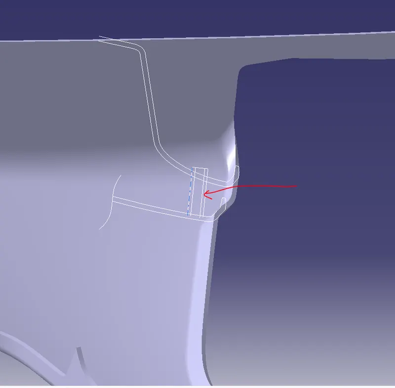
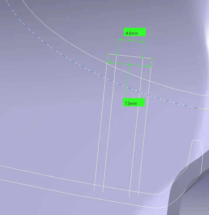
This shows heat stakes to be provided on the lower substrate towards arm rest side and the hole size is 4.5mm diameter and body is 7.5mm diameter. This is for reference and can vary as we create the heate stake and provide draft inside and outside so the section varies.
Some of the standards mentioned and followed is as below. These standards recomended is for good healthy plastic product.
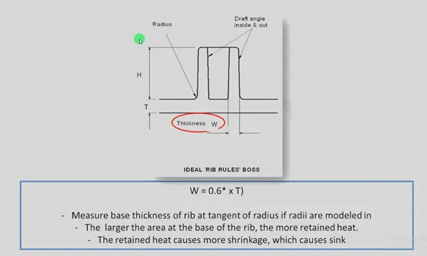
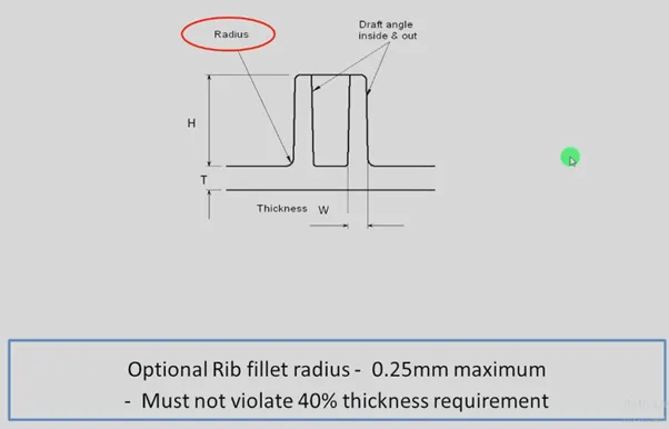
The thickness of the component is 2.5mm W is the wall thickness of heat stake which is 0.6xT=0.6x2.5=1.5mm. So the thickness can be up to 1.5mm and minimum at the edge after draft has to be 0.75mm and above. The wall thickness less than 0.75 in heat stakes is minimum recomended as producing plastic part with less than 0.75mm wall thickness is difficult. All heat stakes has to be provided with bottom radius of 0.25mm as this gives strength for the heat stakes. H is the height of the heat stake and recomended height is based on the diameter of the boss and height to diameter ratio is 3:1. In our case the diameter is 7.5mm and we can design heat stakes 3times the diameter which is up to 22.5mm. Draft of 0.5deg per side for both inside the hole and outside body of boss is recomended.
The heat stake is later heated and a mushroom head is created on the top which covers the flange hole of adjacent part. This mushroom gives a permant rivetting like binding between the two parts. Screws fitting on internal assemblies of automobile is avoided as the cars are on contineous vibrations and screws can get loose. In heat stake vibrations does not affect the binding of parts.
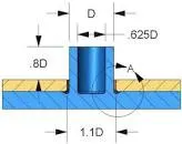
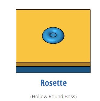
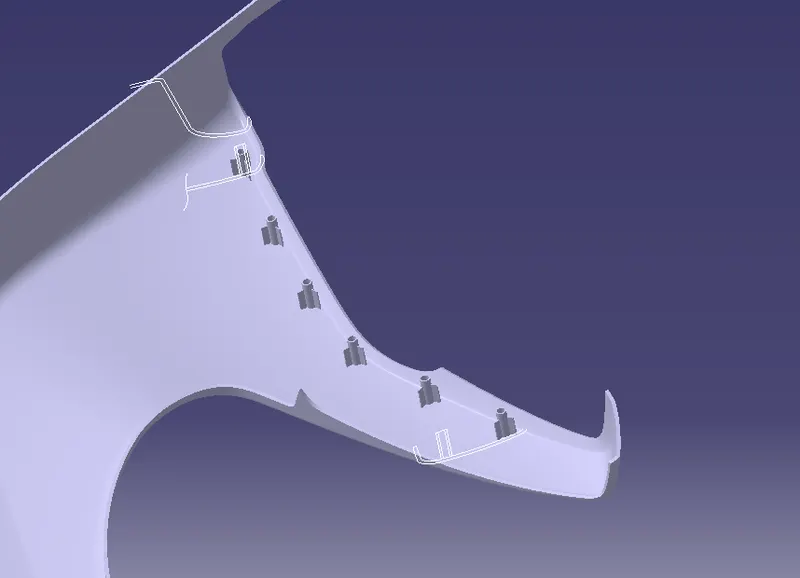
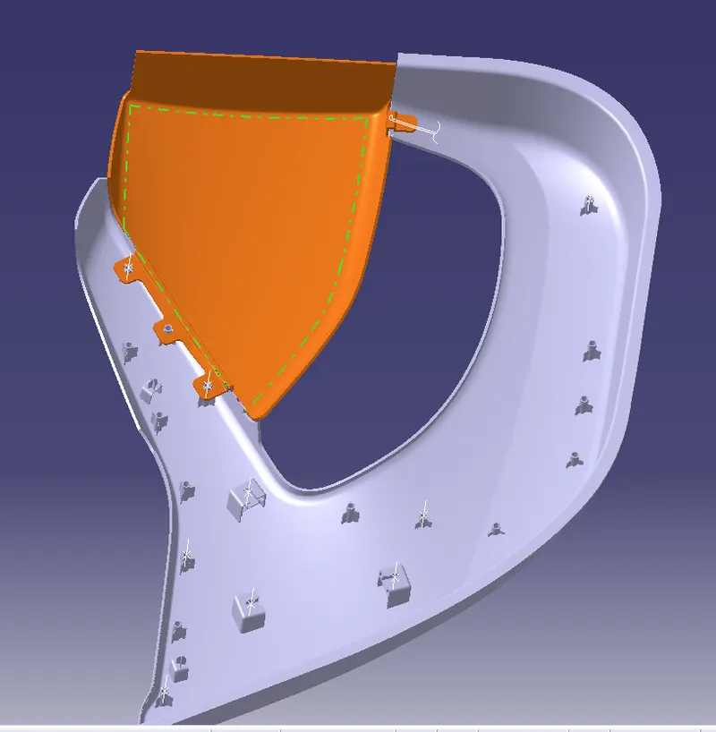
Below you find the heat stackes created on lower substrate for fixing of arm rest. The heat stakes are provided with ribs. This ribs gives resting support for the flange of other part and also strengthen the heat stakes with the main body of lower substrate. Number of heat stakes was decided by the position and a minimum distance of 50mm between two heat stakes was maintained. In our case the pitch is up 60mm between two heat stakes, balance equal distribution along the edge. 6 heat stakes are provided for arm rest fixing.
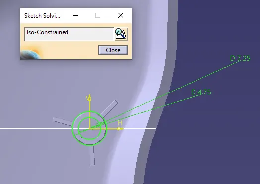
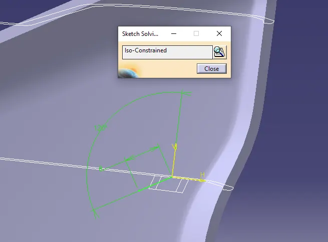
It is advised that any sketches created is normally ISO constrained. Here the sketch fully constrained for heat stake and ribs. One rib was created with pad and this was coppied to three pads by circular pattern. Intially one heat stakes was created and draft was provided. This was copied and translated to the points created. Fillets planned at final complition. Providing fillets was creating problem for any modification. The ribs created height was to be manupulated to match with the flange of corresponding part.
Next this heat stakes was taken as reference for creating flange and hole in Arm rest part. Master section also shows the flange details.
Next is Heat stake creation along side of map pocket as per master section. Three points are created on the edge curve offset and the heat stake and rib assembly was copied and translated to the points.
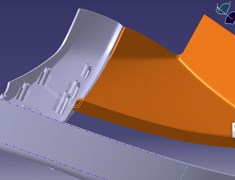
Next heat stakes for locking bottle holder with lower sub strate. Picture below shows heat stakes along the side of the bottle holder on lower substrate.
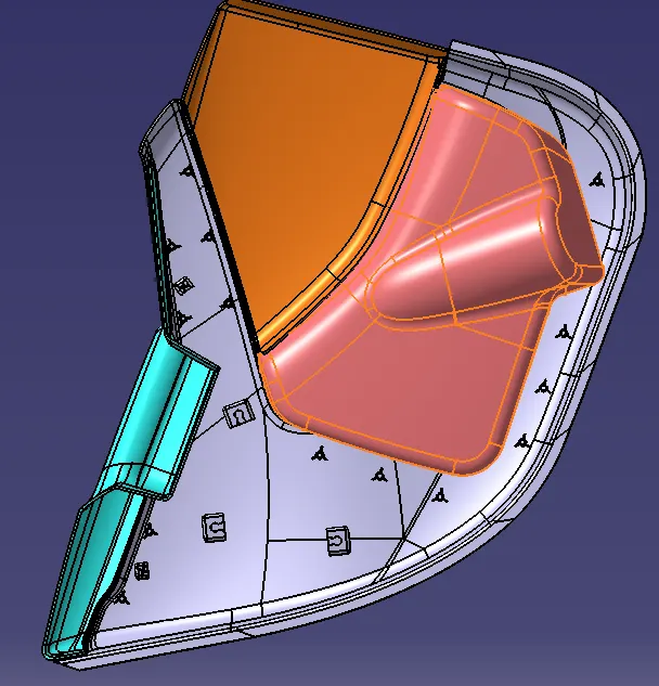
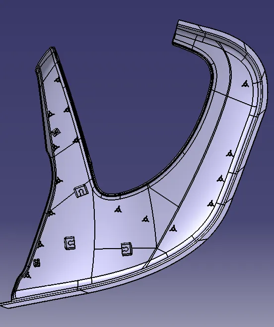
Picture above shows all heat stakes created.
Next is Locators.
Locators used to position and align this sub assembly with the sheet metal subassembly before locking it. There are two types of locators. Two way and 4 way locators. The locators must be atleast 5mm more in height than heat stakes. This is because once the locators is engaged in the holes of the sheet metal than it will be easy for the locking.
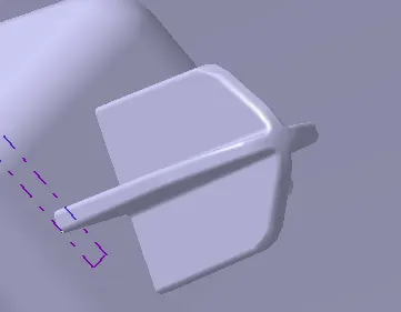 Four way Locator
 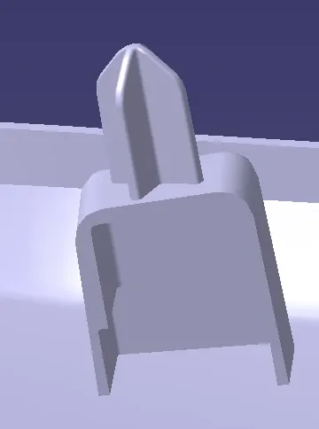 Locator on Dog house
This is a 4 way locator. As mentioned the locator has to be 5mm higher than the locking provision, these can be placed on a dog house. As providing directly on the component and the height exceeding more than 20mm will make the locators week. So pacing them on a dog house gives strength and the required height. The thickness of locator ribs are 1.0mm and the height is 15mm. Top entry chamfer is provided for ease in locating with the holes of the sheet metal part. Draft of 0.5degree per side is provided on all the sides and edge radius is given for smoothness of the part.
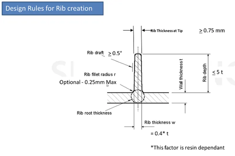
Design Rules for creating Dog house
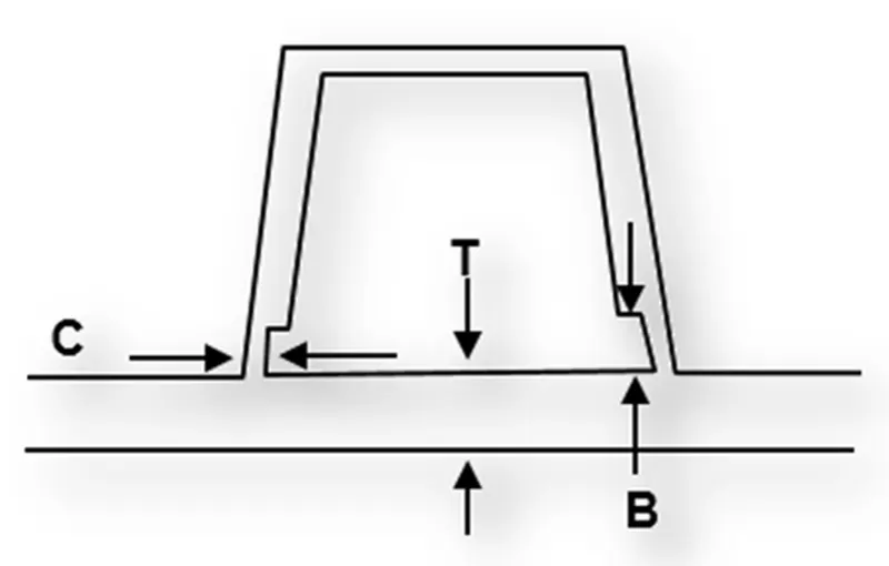
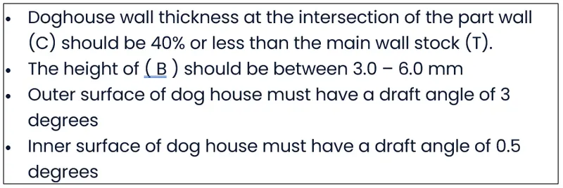
The side walls of the dog house is 2mm all over, but at the area where the dog house joins with the main part the design rules is followed. Thickness is reduced by creation of a stem in the side walls as shown and the thickness merging between doghouse and main part is 0.4T. That is 40% of thickness of part. In our case the part thickness is 2.5mm and 40% of 2.5mm is 1.0mm. These rules are prepared to avoid shrinkage on the outer surface. The dimensions can vary slightly which will not affect very much like in our case 1mm is specified but can vary from 0.8mm to 1.2mm but not beyond. All the side walls are provided with 1 deg draft and inside wall 0.5deg per side along the side tooling axis. The dog house cannot be designed in direct core and cavity molding but requires a side core design.
Locator on the dog house internal part and any shrinkage between doghouse and locator is not a major creteria. So all internal parts can have shrinkage marks but Class A surface has to be perfect and without any shrink or other defects.
After locators Dog house for push pin clips is created. Push pin clip is a quick lock mechanism between the plastic part sub assembly with sheet metal door sub assembly. Once the parts are assembled together with heatstakes, the assembly is than assembled to the sheet metal door assembly by locating the and just push locking using push pins. The push pin is not fixed but just placed on dog house push pin retainers created on the lower substrate. Below is the picture of dog house created for holding push pin. Next is the push pin placed in the dog house.
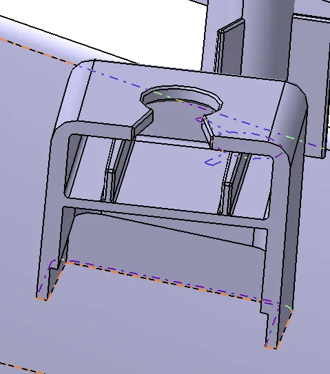
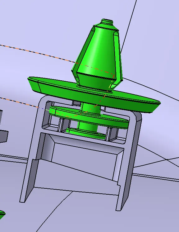
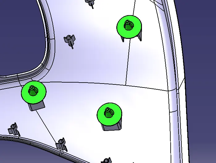
In the picture above three push pins are held in dog house.
With this the inter locking provision on lower substrate is completed. Next is creation of flanges on the corresponding parts.
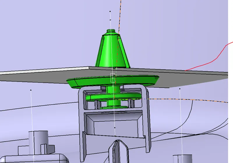
This picture shows the push pin in position in the dog house and on the top is the sheet metal part which the push pin is locked.
Next we start creating the flange on arm rest. Looking at the master section we see flange description.
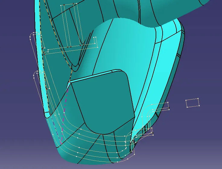
In the arm rest there is flanges for locking with heat stakes of lower substrate and also heat stakes on arm rest for locking with adjacent part. By creating a point on the master section and then isolating the point and again fixing the point with co ordinates, the reference point is created. Then a plane on this point is created for drawing sketches. These sketches are ISO constrain dimensioned so that this matches the master section. See below the flange creation on arm rest.
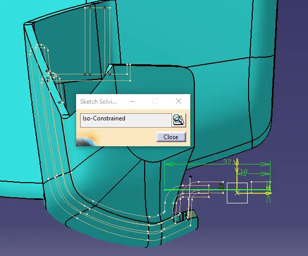
Creation of the flange is tricky process. First a C surface near the plane is extracted and then a line of intersection is created between plane and the extracted surface. This end point of the line is the point for our flange creation. Constrained sketch is created for the vertical portion of the flange and the merging of flange with Arm rest is from the point of interesction line between plane and extract c surface. A multiple extract curve is created all along the C surface where the flange is to be created. Then by using the line as profile and multiple extract as guide curve sweep surface is created. This forms only the vertical portion of the flange. The horizantal portion is created by means of extrude. This is required as the face has to be flat and can have perfect assembly conditions. During such inter locking features, global plane or axis is to be prefered. This helps in perfect assembly conditions or else if heat stake is create in an angle with reference global axis and flange hole also at an angle to the axis, then the flange holes will enter the heat stake but do not perfectly assemble as the axis of both are different. In this case the heat stakes are created with respect to y axis and holes also created with y axis with reference to the heat stake points extracted from the lower substrate. The flange for arm rest is extruded with respect to global axis as shown below.
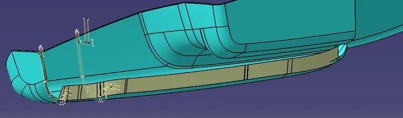
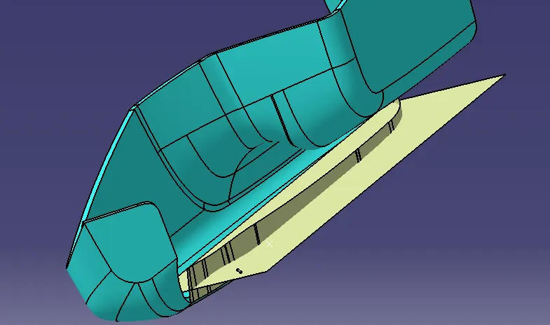
In this picture we see the vertical wall of the flange is following the curve or profile of the body and the horizantal flange is perfectally flat following the global axis. Instead of using such a big flange the surface can be trimmed to smaller flanges as seen in the picture below.These two surface are trimmed and then a thickened part is created which gets attached to the closed body.
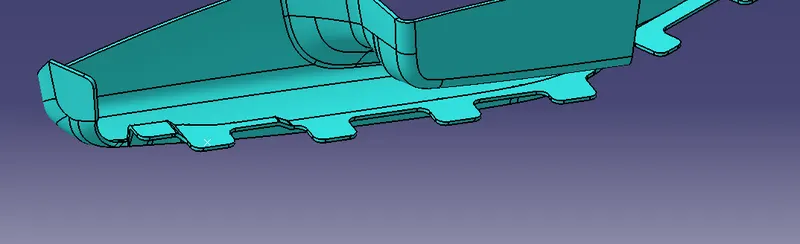
Next is the hole creation on the flanges. Normally 0.5mm per side clearence is recomended. To create the hole in the flange I extracted the surface of the heat stake and then slit hole in the flanges. Hole can be created in different methods. The points of the heat stakes of the lower substrate can be projected on the surface of flange and than a sketch can be created using the point. ( isolate the point and fix with co ordinate) This sketch a circle can be extruded and than holes can be slit in the flanges. Sides of the flange and holes have to be provided 0.5deg per side draft.
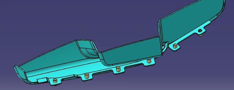
This completes the flange and hole creation. Next is heat stake in Arm rest as per master section.
Taking point on the master section and creating the plane, sketch for horizantal support for heat stake is created.
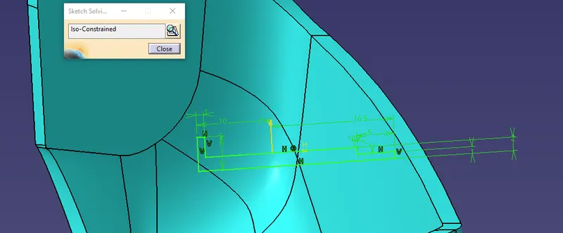
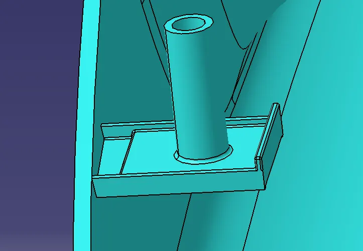
After creating horizantal pad, ISO Constrained sketch is created for heat stake as per master section. In this case a revolved surface is created for heat stake. In the sketch the required draft angle is provided. After creation of the heat stake fillets are provided. Drafts for horizantal pad also is provided. Once this is finished, this pad and heat stake is copied and translated to differnet points as per our requirements. This completes Arm rest B side features.
Next is B side featues on Map pocket
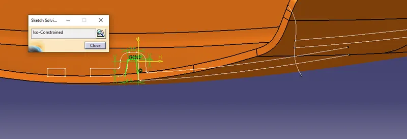
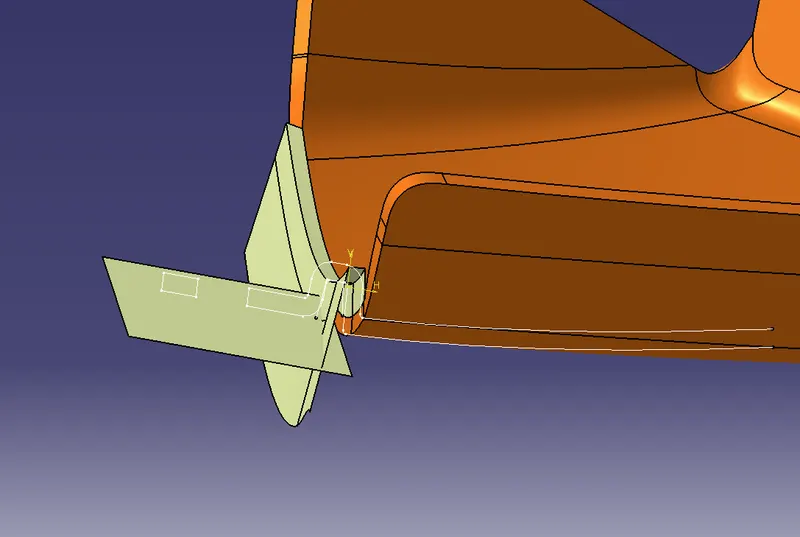
The same procedure is followed of flange wall creation by sweep and flange horizantal face creation by extrude with respect to global axis. Then trim them together and add thickness
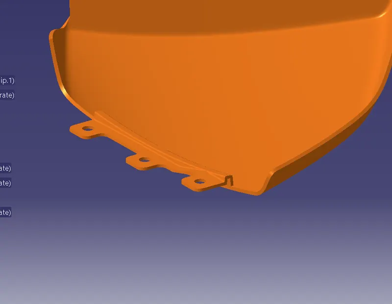
One more flange as per master section is created as shown below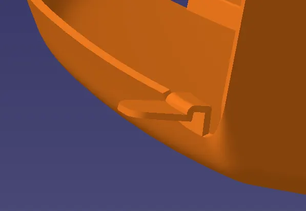
Below you see the final locking between lower substrate and map pocket
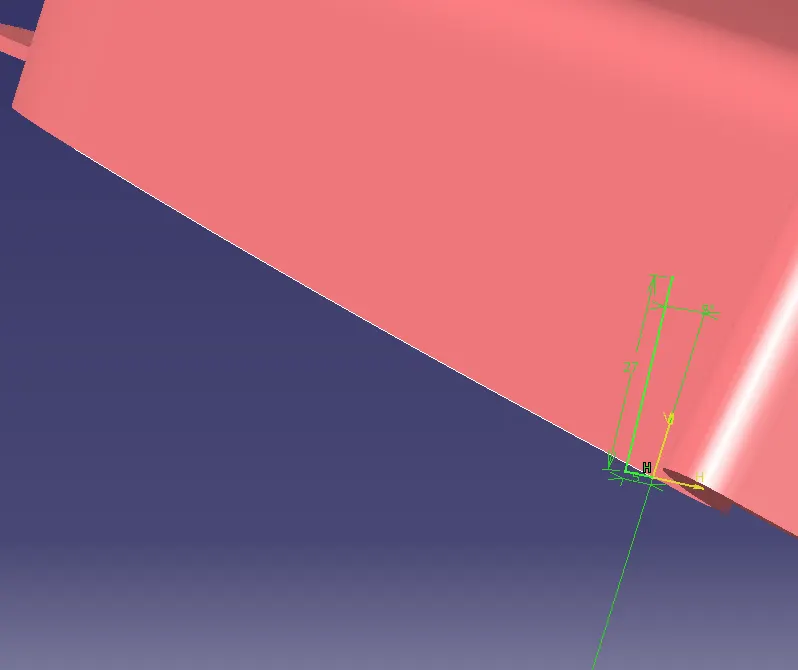
Next flange creation on bottle holder part
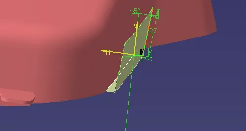
There are three flanges on bottle holder. The flange creation is similar to the other flanges created on map pocket and arm rest. First extract a point from the master section and isolate the point and then co ordinate the point. Create a plane on the point and use this plane and point create constrained sketch Extract the edge of the surface and create intersect between the plane and the extracted surface. Use the edge of the intersection line for creation of flange sketch. Create the flange side surface by sweep using profile and guide curve. The surface will be created along selected edge of the curved surface of the bottle holder.
Then create constrained sketch for horizantal surface of the flange and create surface using extrude with reference to global axis to get flat face. Trim the surface to small flange and then trim the horizantal and vertical surface and then add thickness to the surface.
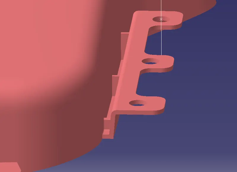
Additiona 3 rib support is provided to strengthen the flange.
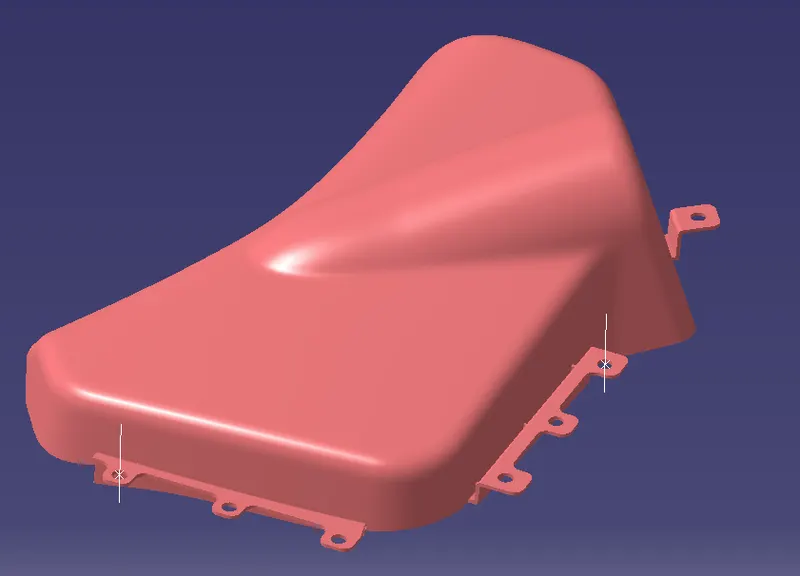
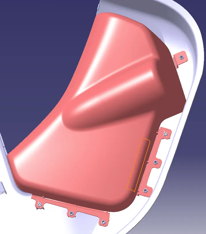
Above you find the flanges for bottle holder
Below all the parts arm rest, bottle holder, map pocket placed on the heat stakes with flanges entering the heat stakes in a assembled condition.l
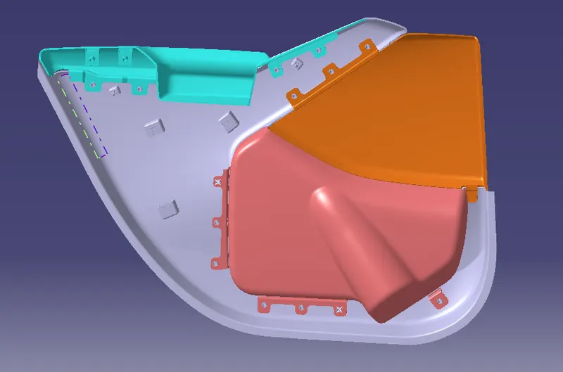
This completes interlocking of all the 4 parts and creating a sub assembly. We have all the B side features on this assembly like heat stakes, flanges, dog house with locator and doghouse for pushpin part.
Next we see draft analysis with B side features.
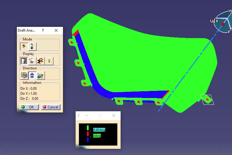
Lower substrate at 0.45degrees
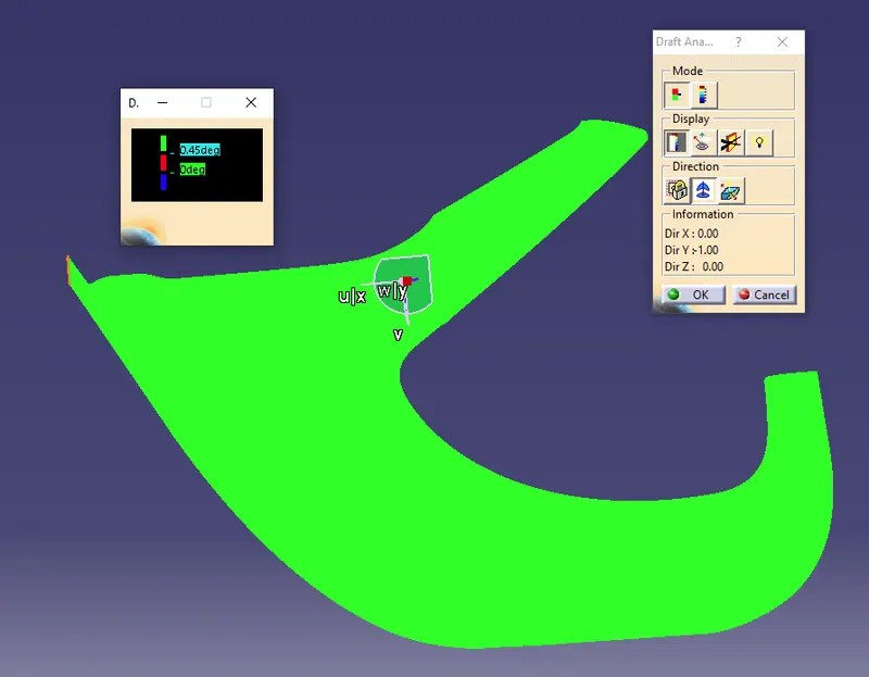
Below draft analysis at 0.5degrees
The draft analysis for dog house is by individual side core axis. All dog house have seperate axis for checking.
Below is one of the dog house draft analysis with 0.45 degree and 0.5degree with side core tooling axis
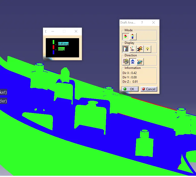
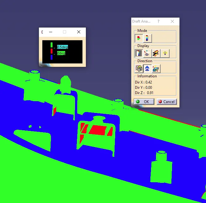
With this the draft analysis for lower substrate is cleared.
Next is arm rest.
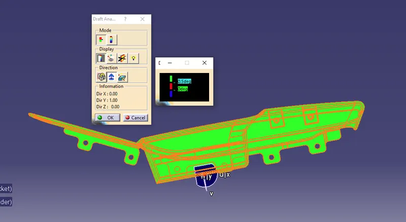
Sides of holes and flanges clearing the draft analysis at 0.5degrees
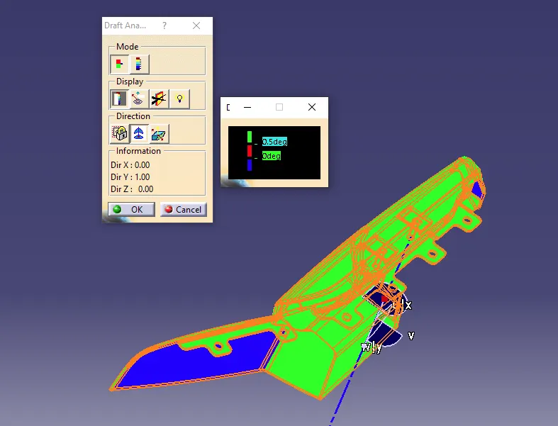
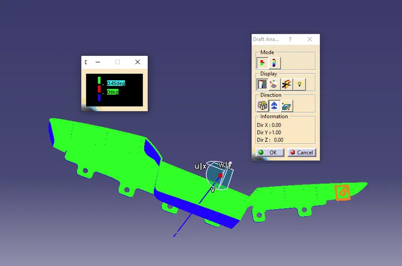
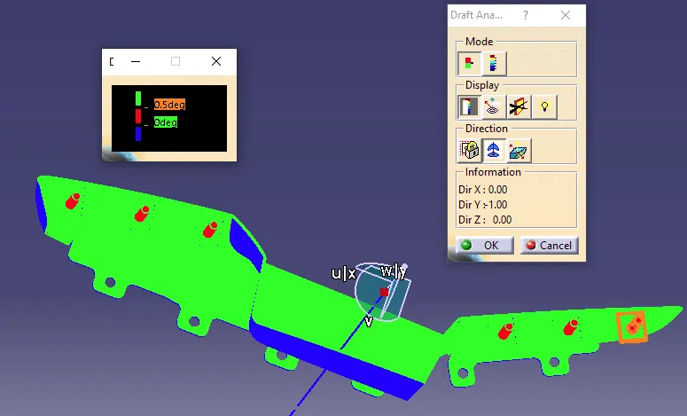
Horizantal heat stake draft analysis at 0.45deg and 0.5deg.
Next Draft analysis for Bottle holder after B side features.
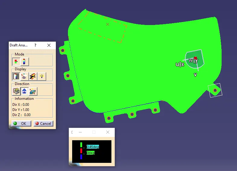
This tooling axis is with global reference so B side features of flange and flange ribs, holes is cleared. But main component does not clear draft analysis. Some changes requires.
Next is draft analysis of Map pocket after B side features.
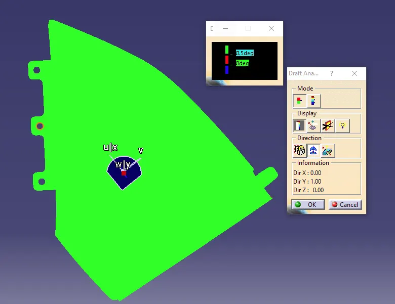
This completes the final project which includes creation of all the 4 parts into solids and joining them with B side features and checking them for tooling feasibility with draft analysis. All these are explained above.