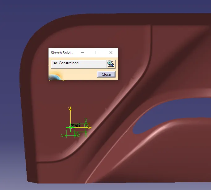
Week 9 - Project 1 - Door Trim Lower with Engineering Features
Challenge is to create B and C surface using the A surface provided. Thick ness is not mentioned assumed as 2.5mm
Draft analysis on Class A with reference to tooling axis.
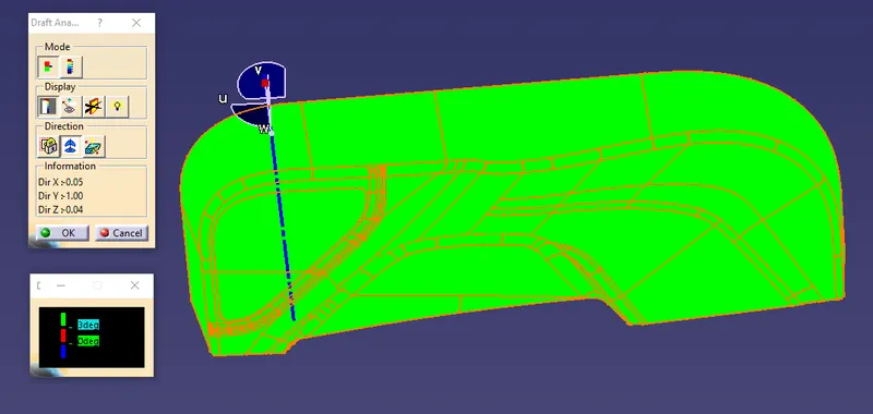
Creation of tooling axis
For creation of the tooling axis, a flat surface from the class A was extracted and used. A point was created on the surface and line created with reference surface and point. This line was taken as tooling axis and in the above picture we see Class A surface draft analysis picture at 3degrees.
Here we have not considered bisecting method instead a flat surface was considered for tooling axis creation.
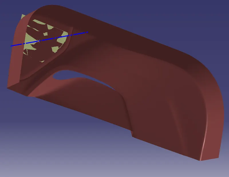
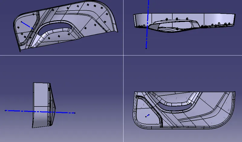
Picture of Closed part with heat stake and two 4way locators.
Draft analysis of the complete part including heat stakes with reference to tooling axis at 3degrees
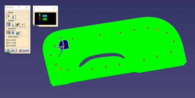
Draft analysis is a procedure for the part developer with due consideration of manufacturing. A plastic part requires sufficient draft for ejection.So the part developer can develop the part with reference to the tooling axis. Hence the creation of tooling axis is essential and first thing in designing of a part.
Below some of the pictures of sketches used for locators creation