Wiring harness routing & packaging Rules Week 3 Challenge
Challenge is to convert the mechanical part clip and back shell into a electrical component and create corrogated tube part and define them into electrical part and add them in the catalogue.
First downloaded the p clamp 3D data from the link.
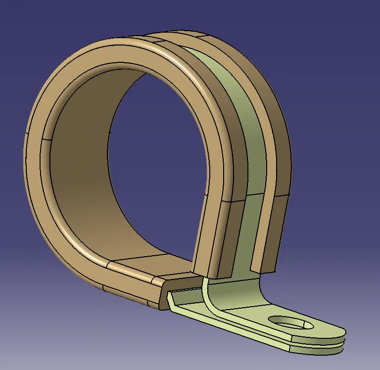
Opened it in catia and saved it as .Catpart in the same name and same folder. Then created centre point on on the curve
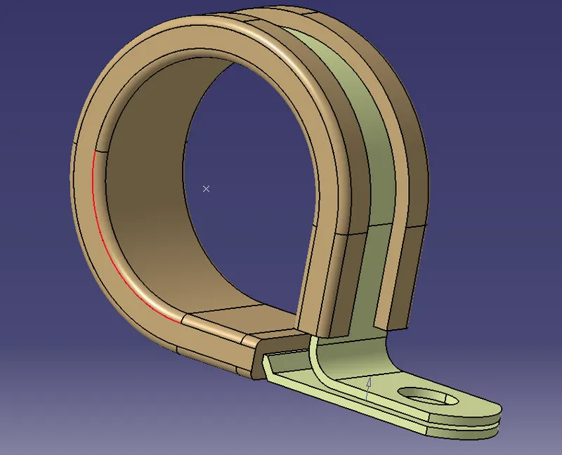
Similarly created centre point on the other side. Then created a plane on the selected surface and at the point created
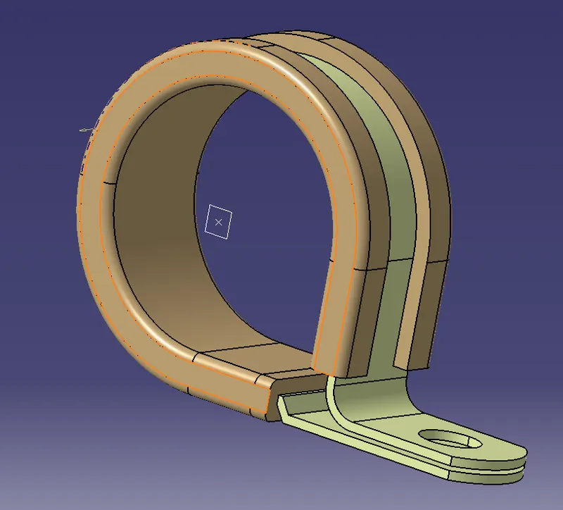
Similarly created plane on the other side on the face and at the point created. Next a third plane is created at 2mm from the flate surface
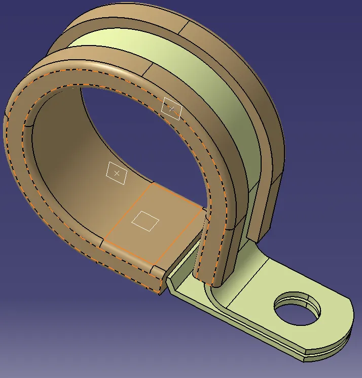
This file is saved and opened in Electrical part design environment to convert this as "electrical support part".
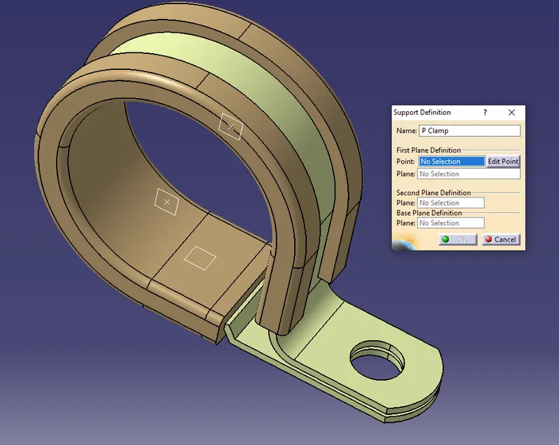
Once this command is selected, it asks for the part to be designated as support and we select the p clamp, after this it opens a window as seen above.
Name is same P clamp along with name we can give size of p clamp in this case the inside diameter is 28mm. we can name it as p clamp 28 when we use different size p clamps. Now we retain the original name P clamp.
Next it is asking first plane definition and is asking to select a point which we want to designate as first entry point. We select the visible point as the first point and then it ask for the plane where select the plane on the point.
After this the window is asking for second plane definition which is on the opposite side. Here we select the plane on the opposite side and then it asks for base plane and we select the bottom plane created offset from the surface.
Since this p clamp can be used from both the sides we define this p clamp with the opposite side as entry point. Again we define the part as support part. When the command is selected it asks for the part and we select the p clamp.
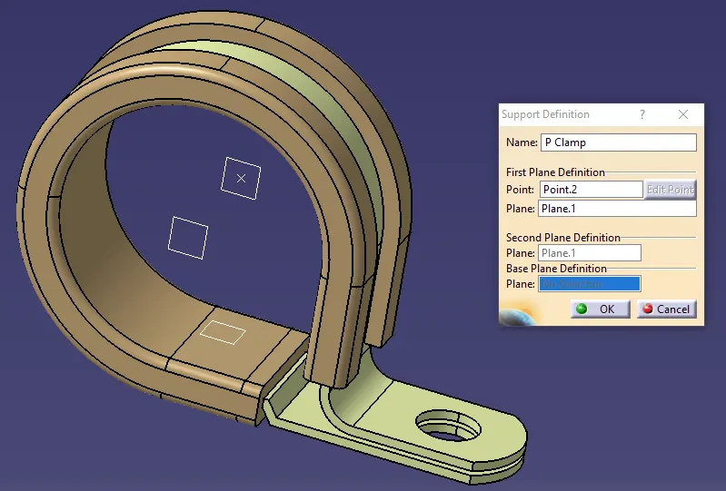
Next it asks for a first plane and point of entry. Since we have selected the one point as the first entry point, this point is now hidden and not suitable for selection. So the second point on the other side is visible and we select that point as the entry point and select the plane as first plane. The second plane is automatically selected and also the base plane is selected so we press ok. So the P clamp is defined with entry point from both sides.
Next this is added as P Clamp to the catalogue by using store device and we add this under mounting brackets and clamps which we had created in previous challenge.
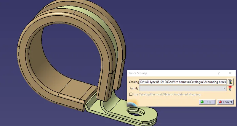
This complete the P clamp challenge.
Next is to down the link given Tyco 1738312-1 https://www.te.com/usa-en/product-1738312-1.html
In the downloaded part add the required point and axis and define this as electrical part and add to the catalogue.
By selecting the link we are directed to the web page
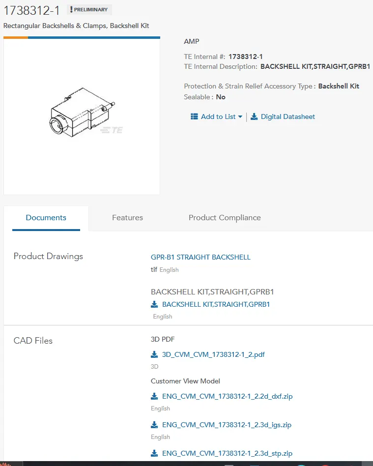
This link directs us to TE wed page GPR-B1 Straight Backshel.
I download the CAD data zip file in stp format in the folder wk3 challenge and extract the file in this folder. The downloaded part looks as seen in below picture.
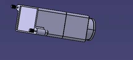
This part is saved as catpart in the same folder.
Next is marking of the point and axis for defining backshell connecting point.
For this a mid point is created on the mating face of this back shell with connector which is as seen below. Selecting two coner points a mid point is created and then a axis is created with y axis projecting out and x axis is horizantal and z axis is vertical.
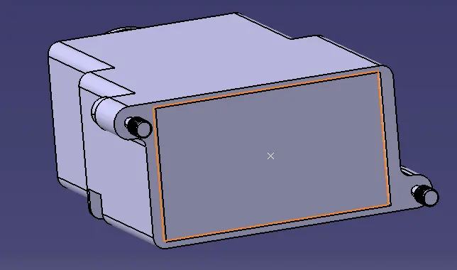

After creation of the point and axis of the backshell connecting point, bundle entry point is to be created opposite side of this face.
Point is created in the centre of the circular area of back shell as shown.
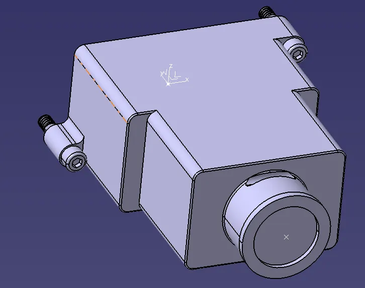
Next this is saved and opened in electrical part environment for defining this as backshell and also to define the connecting points.
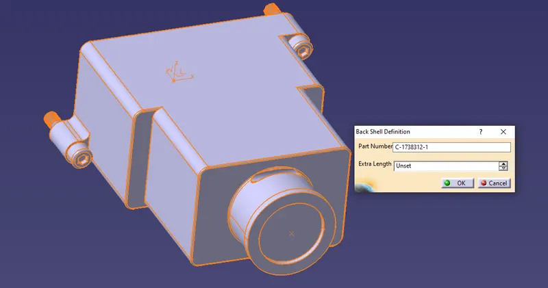
When the command to define the part as backshell is opened, the above window opens in which it is asking for the name/number for the part. I retain the same part number specified by manufacturer and for the second option of extra length, the unset option is retained and ok is selected.
Next the command define back shell connecting point is selected, it ask for the part and we select the displayed part. A window opens aksing for the parameters as seen below.
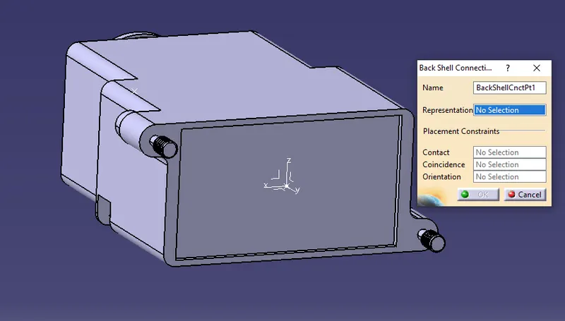
Representation is the point we have created and we select the point, contact is the face on which we have created the point, Coincidence is Y axis and orientation is x axis selected and ok is selected. This defines the back shell connecting point.
Next defining the bundle entry point. When we select define bundle entry point command, it asks for the part and when the part is selected, the below window is opened.
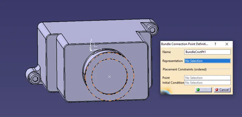
Representation is the face of the backshell, point is the point we have created and intial condition is the same face of backshell. By selecting ok the bundle entry point for this part is defined.
Next I am creating a new catalogue file named back shell and saving it in a folder. The new created back shell is now added to the new catalogue by store device command. So this part is stored in the catalogue and can be added in the assembly whenever required.
Next in the challenge is to create corrogated tubes as per the details given
Stating with 12mm ID.
First opened a part file in catia and named it as "Slit_COT_12mm" and saved
Next changed the environment to electrical part design. In electrical part design selected the command 'Define Protection Part'
The window apprears as seen below
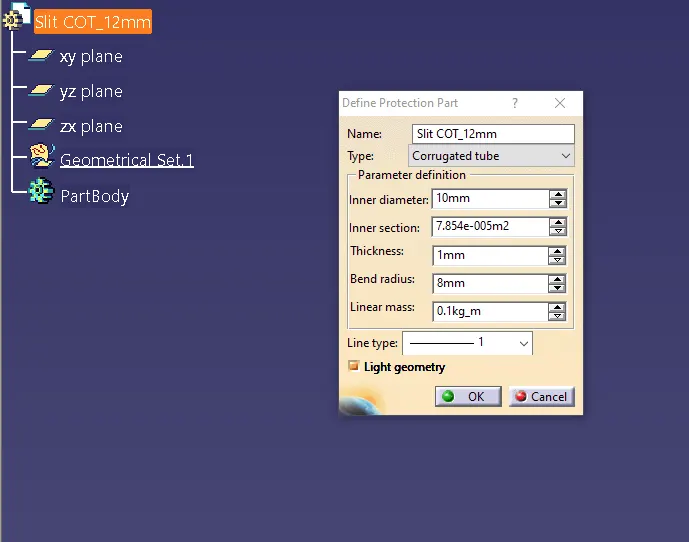
Next started entering the requirement to be filled in the window.
Type has two options 1. corrugated tube and other 2.Tape.
Here we are defining corrugate tube and so I select the same.
Next Inner diameter and first tube we are constructing is 12mm
Inner section is auto calculated.
Next thickness and for 12mm it is 1.5mm in the table mentioned.
Next is bend radius which is minimum 1.5times diameter which is 1.5times OD 15mm and is 22.5mm. So I select 23mm and select OK. There is a option to select line type which we leave it and for light geometry it is recomended to select. A electrical part slit_COT_12mm is created as seen below.
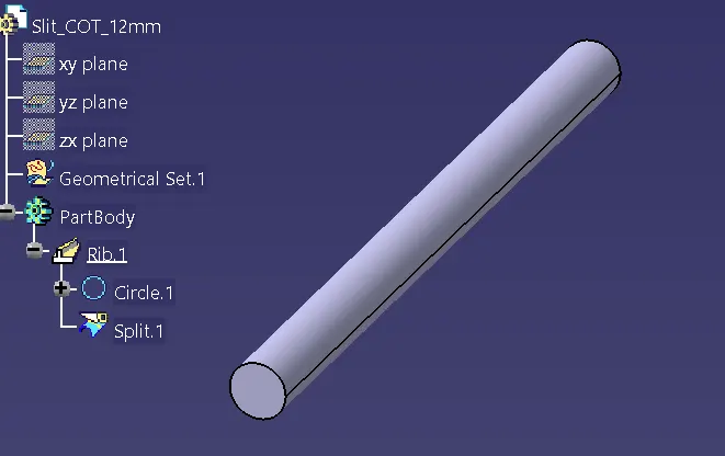
After this a new folder is created as COT_Tube and we save the above part as 'Slit_COT_12mm'.
Once this part is saved we have to create catalogue for the COT_ tubes as mentioned in the challenge in the name of Slit_COT.
so we open a new catalogue document file. Select the command add family and a window opens as seen below. In the window we enter the catalogue name as Slit_COT and select the type as Conduit and select OK
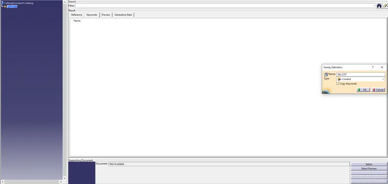
After creating the catalogue file and saving in the destination folder, we create all other part files.
next I create 4 more catpart file with the above specified data with bend radius at 1.5times OD.
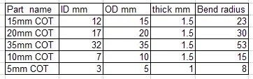
Now I add all the 5 files created in the catalogue under the family Slit COT and save.
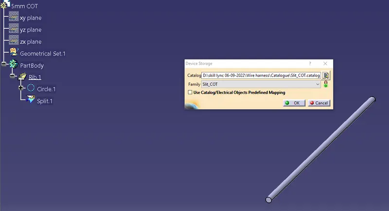
This completes all the challenge requirement