Roof Design
Designing of Roof with associative components
Assembly to include Front roof bow, Centre roof bow, Rear roof bow and atleast roof bow1& 2
First designing process
Started CAD design in roof assembly file. Imported the given roof skin made copoies of this and started working on half section of the part.
Started with front roof bow with master section as reference created offset of surfaces. The front roof bow surface is at 32mm offset from the top roof. There is no dimension of the ditch height and front roof bow height merging with top roof ditch. It was assumed half at 16mm and created the part mode. With law of extension created side ditch wall at 7deg with refenence to skin surface. From there again created parallel to top surface at 0deg ditch sides at 21.5mm as mentioned in master section. From this face offsetting to 1.5mm the front roof bow was started and offseting the side wall of ditch to 80mm the front roof bow was created.
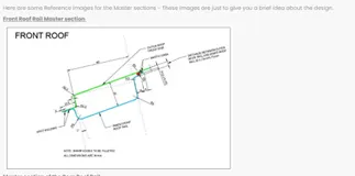
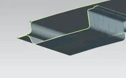
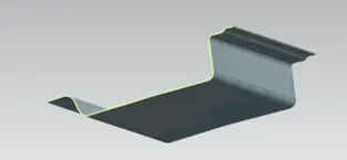
master section Front roof bow with roof front bow roof part.
Next the ditch area of rear roof was created as per master. Created a side wall at angle of 28deg to a length 40mm and then a vertical wall was created with law of extension. The ditch area was completed as per master section and with reference to the ditch area back roof was created using master section reference. Dimensions not mentioned in mastersection was assumed approximate. All sharp corners were blunt to radius.
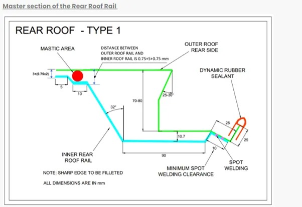
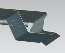
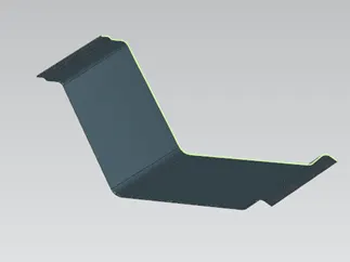
Master section of rear roof bow Rear roof bow with roof ditch in assembly Rear roof bow part
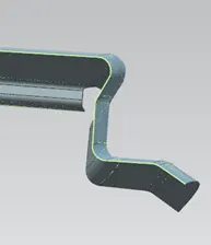
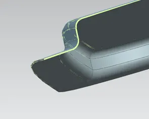
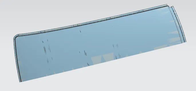
Ditch area of rear roof bow Roof view with side ditch area
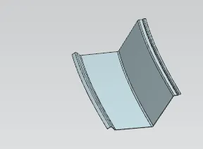
Next the centre roof bow was started with offsetting the roof surface and creating curves and offseting the curves the centre roof bow model was completed using the master section. At the end a 80mm length was trimmed to merge the end part of centre roof bow with top roof ditch area. A merging profile of the centre roof bow and flat area of the ditch surface was created. The ditch surface was used by wave geometry trimmed and matched as shown below
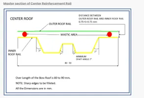
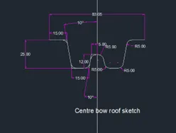
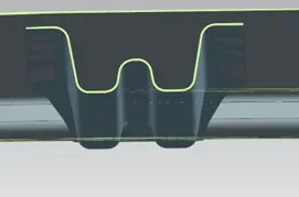
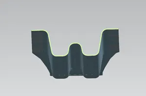
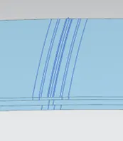

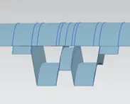
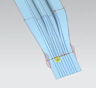
Next is Roof bow 1 and 2.This is very similar to centre roof bow and same procedure was followed to create the parts.
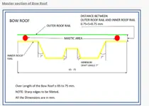
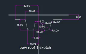
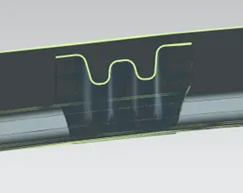
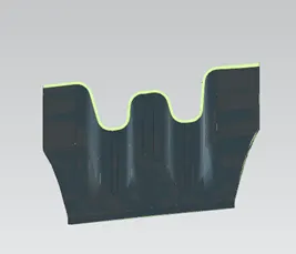
The parts looked as below
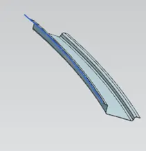
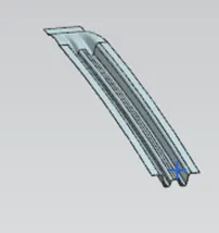
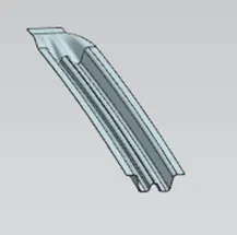
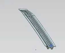
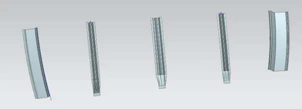
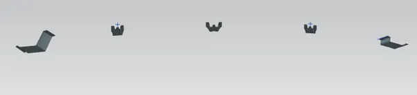
In the assembly the centre roof bow was placed exactly at the centre and first roof bow between the front and centre was placed at 25% from front which is in between front and centre roof bow. Next the roof bow 2 was placed at 75% from the front which is in the centre of centre and rear roof bow.
All the above parts finally was extended at the y0 and trimmed to the plane, mirrored and finally thickened to 0.75mm.
Next is draft analysis calculation
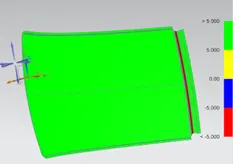
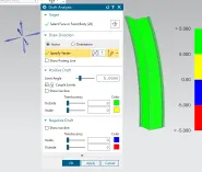
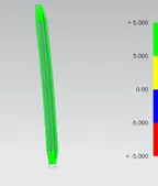
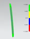
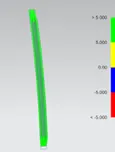
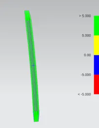
In the above draft analysis the red area in the roof is because of the negative profile at the roof ditch area. This profile will be achived by secondary operation in and cannot be achieve in direct draw.
Next is Bow-Roof prediction calculation as per formula
Curvature study of roof based on the formula. Skin of the roof was considered for study.
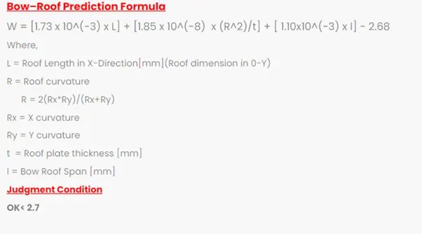
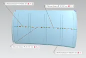
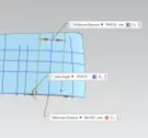
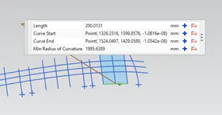
creating curves on the specified points which is along y0 and then offseting the curve on the surface at -3y which is 300mm from the centre curve and then again offsetting the -3y curve 100mm on either side, readings of the radius was found and data entered in the table created for calculation as per formula. Four points assigned and reading were taken. The points are on -3y line in the centre of the front roof bow edge and roof bow 1 edge. Next point is between the roof bow1 and centre roof bow, another point between centre roof bow and roof bow2 and finally between roof bow2 and rear roof bow. At these points readings of curve noted and entered in the table.The curvature measured at 200mm arc at -3y points was noted as Rx. To get Ry curves were offset at the centre points of front roof bow edge and edge of roof bow 1 and then offsetting 100mm on either side the curve readings were noted for the 200mm length exactly on y0 section portion and entered in the table Ry. Thickness already mentioned 0.75mm and L is the length of the roof at Y0 section. I is the distance between the inner edges of the front bow roof and roof bow 1, roof bow1 and centre roof bow inner edges, centre roof bow and roof bow2 centre edges and finally between inner edges of roof bow 2 and rear roof bow.
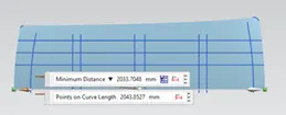
L= length along Y0 section see above.
R= Roof curvature, achieved by the formula. We have noted Rx and Ry and based on this R is arrived.
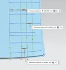
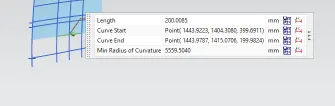
Section and curves for Ry
t= thickness of sheet 0.75mm given
I= bow roof span, the distance of edge of one bow roof to next bow roof.
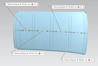
Table of calculation and result below.

The conclusion is W is below 207 and curvature study is OK
Next is Snow load predictation calclulation.
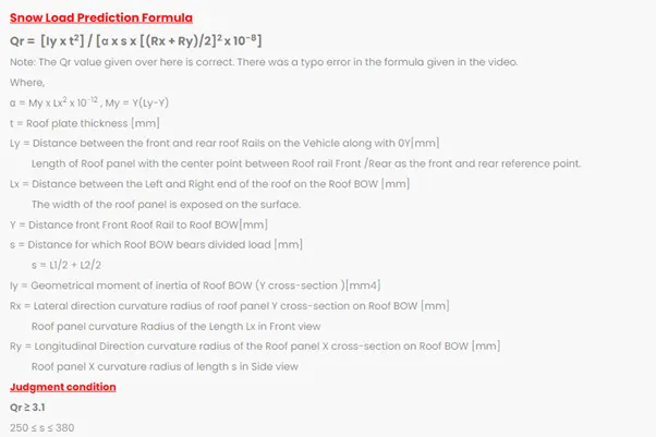
α is arrived by using y, Ly
t is thickness 0.75mm
Ly is the length of roof from front edge to back edge on section Y0
Lx is the width of the roof left to right edge at the measuring point of Rx and Ry.
Y is the distance mid of Front roof rail to mid roof bow1 and further between mid of two roof bow's.
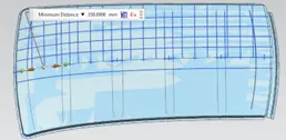
S is the distance from half point of front bow roof and roof bow1 and similarly between the mid points of each roof bow's
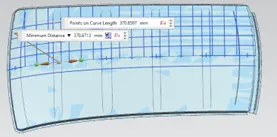
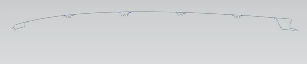
Iy is geometrical moment of inertia of each roof bow. These readings are extracted from nx as shown below
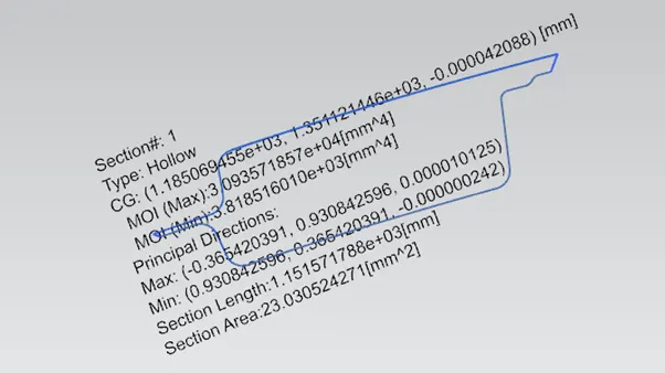
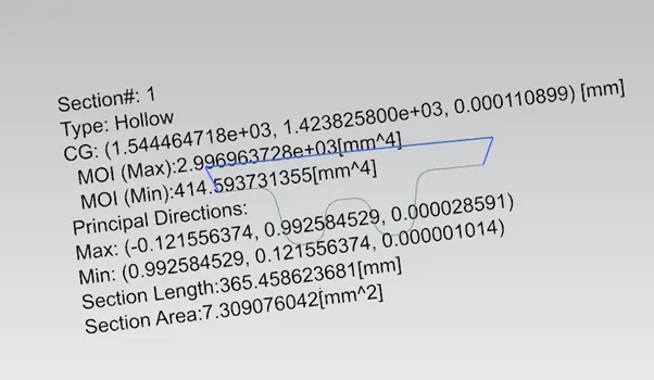
Front roof bow section inertia reading Roof bow1 section inertia
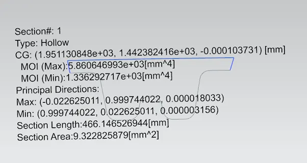
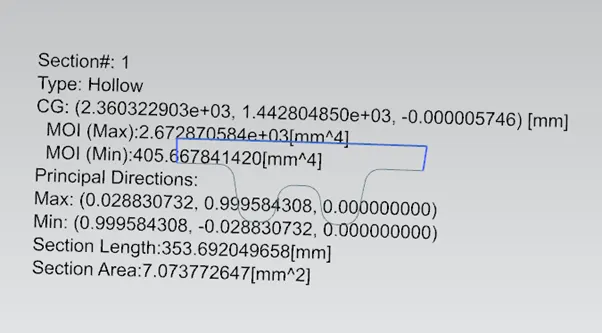
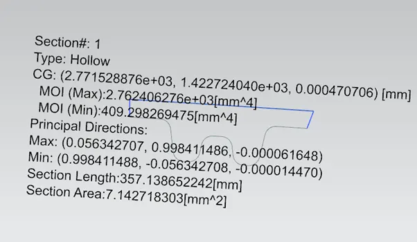
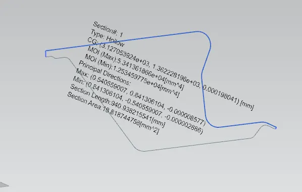
With all the above readings entered in the table we get the below reading

In the above the snow load prediction is passed, but the S value which is to be above 250 and below 380 was found more. So as a remeady one more bow roof3 was added inbetween centre roof bow and roof bow2. The roof bow1 and centre roof bow was move slight towards front side and roof bow3 was accomodated inbetween. with this addition the S value reduced but still more than the requirement.

conclution is the roof snow load prediction can be passed ok