Week 14 challenge
Challenge is to create a Butterfly valve assembly from the 3D models we have created.
The main parts are
1.Body
2.Stem or shaft
3. Disc plate
4.Handle or lever
5.Retainer plate
6.Nut
Started with creating new assembly file with name Butterfly valve assembly. Added all the six files in to the assembly work bench and this file was saved in the same folder where the above parts was saved. All the parts were loaded in a scattered way. Now Body was constrained by fixing and started adding constrains for other parts.
First a sub assembly of shaft, disc plate and screws was created outside. The disc plate with two holes was constrained with axis of the two holes of the shaft.
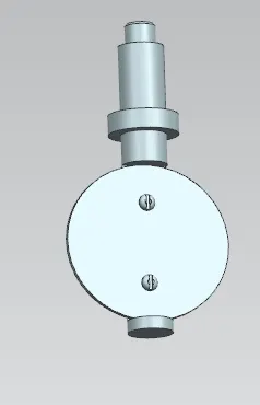
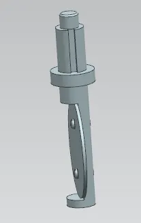
This assembly now was constrained with the body. The shaft axis was constrained with the bore in the body
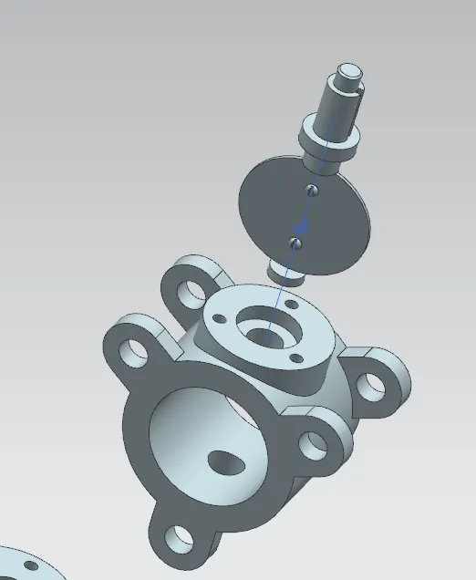
Next the diameter face of the disc plate was touch constrained with the bore of body as shown and the assembly is a shown below.
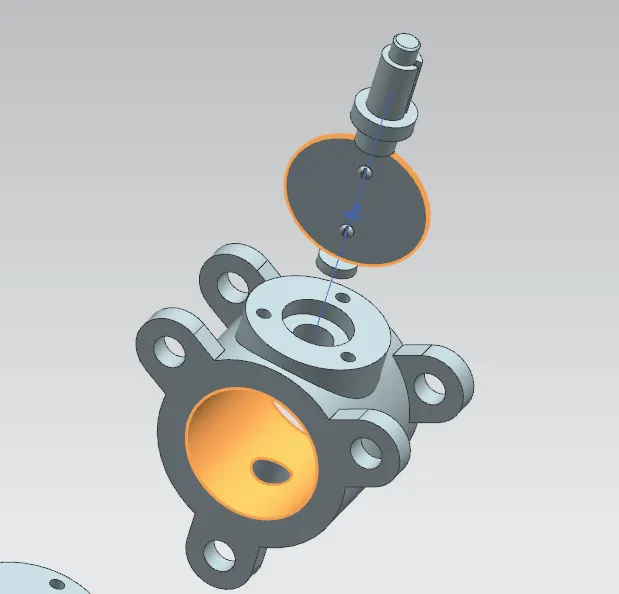
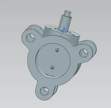
Next the retainer was constrained. The axis of the bore was constrained with the axis of the shaft and the face of the retainer touch constrained with face of the body. The assembly looks as below. Screws were fixed in position.
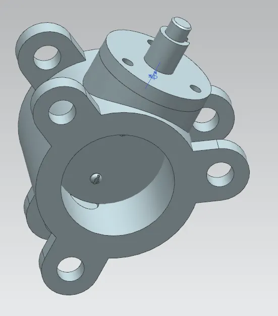
Three screws was added next with axis and face constrain.
Next the lever was constrained. The bore axis of the lever was constrained with the axis of shaft and the face of the lever was touch constrained with retainer.
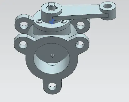
and finally the nut constrained with hole axis with shaft axis and face of the nut with face of the lever.
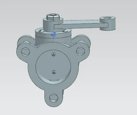
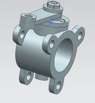
This completes the assembly of the buttefly valve assembly.
Next is the creation of the 2D drawing of the assembly and applying the GD&T.
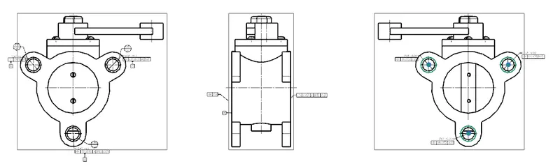
In the butterfly valve assembly there are two important faces. All other parts are controlled in the individual drawings. In this valve the two faces are going to be connected to another mating flange of a pipe. So the face of the valve and the hole pitch are important parameters. First the face of valve is applied with flatness tolerance of 0.2 and designated as datum A. This datum A is at 3 places A1, A2, A3 and together they form A datum. The datum A1 A2 A3 are 60mm diameter around the hole. Next dimensional tolerance is applied for all the hole dia47 +or-0.1mm. Then a perpendicularity geometrical tolerance of 0.2 with reference to datum A is applied to one of the hole and this is named datum B. Next one more hole is applied with position tolerance of 0.2 with reference to datum A and Datum B at maximum matrial condition. This is named as datum C. For the third hole position tolerance of 0.2 is applied with respect to datum A B C at maximum material condition and material boundry modifier is added. With this one side of the butterfly valve is applied with GD&T.
Next on the opposit side a profile tolerance of 0.2 with respect to datum A B C is applied. The holes are provided with dimensional tolerance and a hole position tolerance with respect to the opposite side datums respectively.
There are no other important working area which requires precision GD&T. The 2d drawing shown above is fully constrained. Parts and assembly folder attached.
This completes the challenge.