Wiring harness design in CATIA V5 - 3D modeling Week 4 Challenge
Routing of the wire harness as per the diagram provided.
Assumption of the wire diameter to get routing harness diameter.
I start with down loading of the connector CAD data and defining it into electrical component. There are 4 connectors given and all are DT series which means they are DEUTSH connectors. so I open the TE.com web site and down load the connectors.
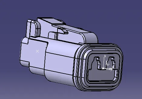
The picture above is DT06-2S. After downloading and opening the part in the catia I save this into Catpart. Then in part environment I mark the centre point of the connector connecting face. Create axis at this point with y axis projecting out x axis towards locking and z axis showing horizantal. Then I go back of the connector and mark centre point on the surface and this will be bundle entry point. After defining the points and axis i switch over to electrical part design environment. First I define the component as connector. Then I define the connector connecting point. I retain the same name and Representation is the centre point where axis is created, Contact is the face on which is created, Coincidence is Y axis and Orientation is x axis. Once defining all this parameters I add this to the connector catalogue by slelecting store device command then save the part file and exit.
Download a new connector CAD data. The downloaded part DT06-06S looks as seen below picture.
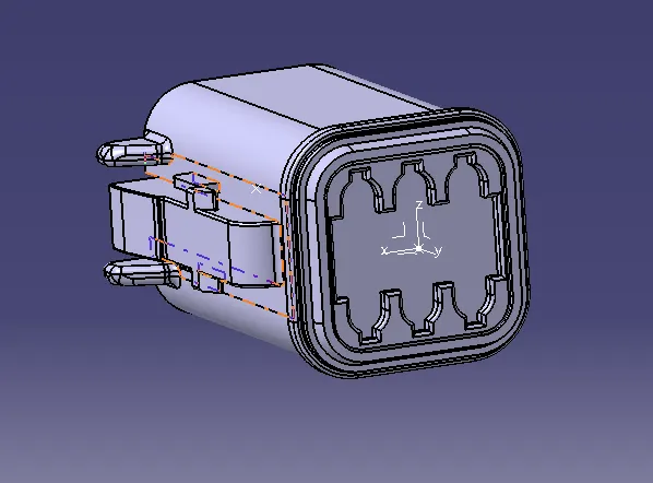
Next I down load the next connector DT06-04S from TE.com. Open the 3D data in catia. The part looks as below
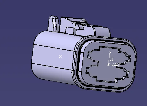
Next I down load the next connector DT06-08S from TE.com. Open the 3D data in catia. The part looks as below

These part is individually opened in catia saved as catpart and then required point and axis is created. Then the connector connecting points and bundle entry point is specified and then converted into electral connector and the entry points are designated. Finally added to the connector catalogue. This completes the defining of this connector. The part is saved and closed.
Then I create a product file "WK4 Wiring Harness Assembly". In this I create one more product by using Insert option and command "New product". This product file I name it as WK4 Assembly Geometrical Bundle
I open WK4 Geometrical bundle file in a seperate window and copy all the connectors required.
In the wiring diagram the distances are specified. To position all the connectors I require a position. So I create a part file with name connector position points. In the part file I open sketch and create points at the dimensions given in the diagram.

this is with reference to the diagram provided by you. This part file is now copied in product file that I am working.
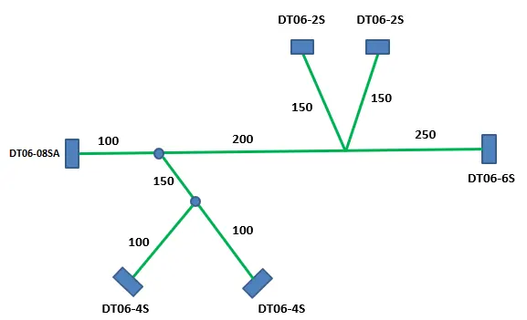
I position the connectors as per the specification of connector based on number of wire entry. The positioning is done by using command snap-Smart move command. After positioining of al the connectors I save file and change the environment to Electrical Harness Assemlby for routing.
Next is Routing.
Here I am using 4 different connectors
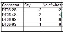
to know the routing diameter, I have to find the wire diameter. From the TE web page I get the information of wire diameter for DT series connector and this is displayed below.
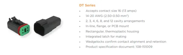
in the specification of TE wire diameter is 14-20AWG
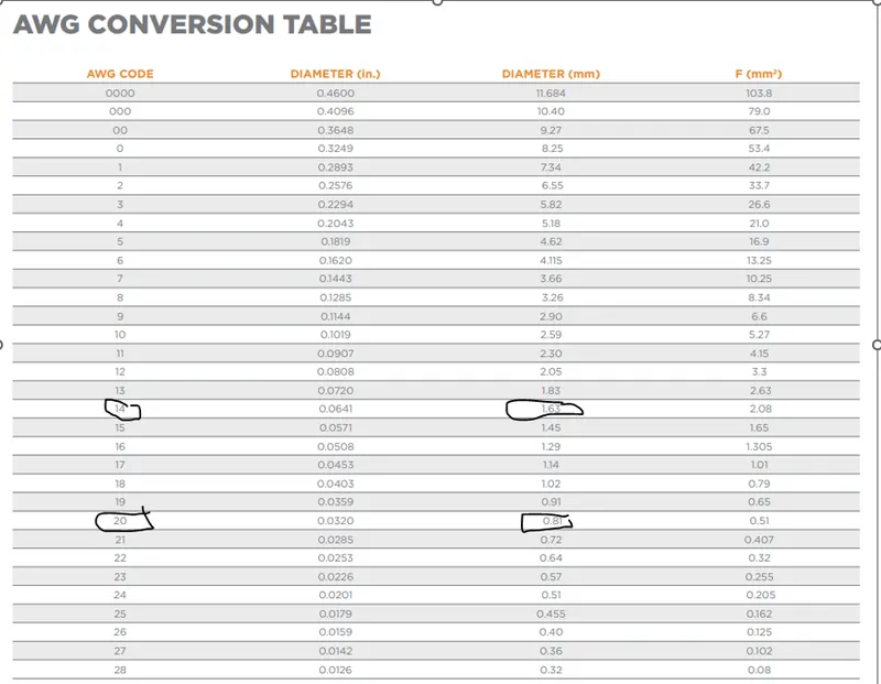
from this AWG conversion chart we find that the diameter of wire is between 1.63mm to 0.81mm. Next we have insulation on the wire and the wire diameter after the insulation will be as per the chart below.
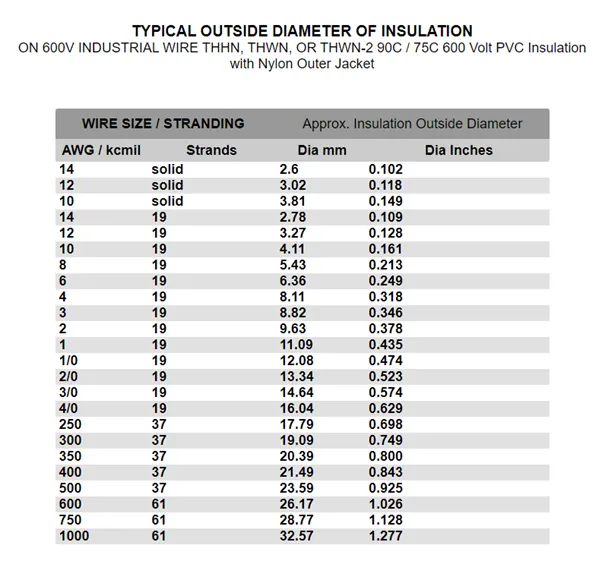
for 14AWG the outside diameter will be 2.6mm. So we have to calculate the routing diameter based on the number of wires bundled together.
The first connecter DT06-8S will have 8wires of 2.6mm and I find below ID of routing will be dia 10mm I can consider 12mm for this so all other will be below 10mm diameter. For two wires bundle I am considering 6mm ID, for 4 wires I consider 8mm ID, for 6 wires I consider 10mm ID, for 8 wires I consider 12mm ID.
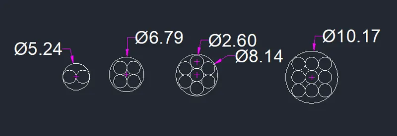
Next we start routing.
Below is the position of connectors and ready for routing.
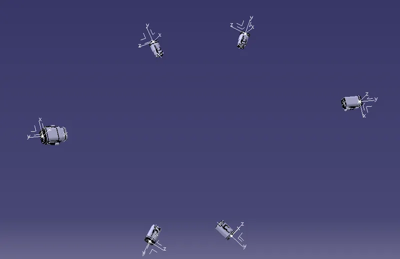
I start in Electrical harness assembly environment and start a Multi branchable
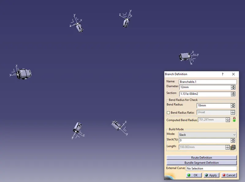
The window opens. First in the window is name which is Branchable1. I retain this name. The name can be change as per requirement like the use in assembly like Battery for wire terminating from battery, to indicator if the wire is going to indicator.
Next is the diameter which here bundle diameter. I select 12mm as I terminate 8 wires out of this. Next is bend radius. The bend radius depends on the diameter of the bundle diameter which is normally 1.5times the bundle diameter. In our case the diameter is 12mm and 1.5x12mm will be 18mm I consider 20mm.
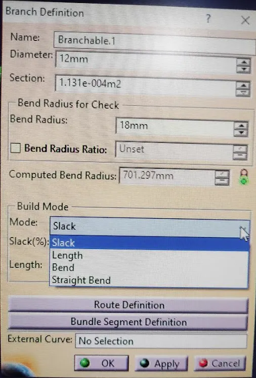
Next there is a mode called slack. This helps in providing flexiablility of the wire length. Normally the wire bundle we specify is exact to the dimension. To get some flexibality we use this mode and slack is one of the mode. This gives extra length which helps in connecting the connector or removing the connector. The length of slack is normally mentioned on percentage. It can be 5% to 10% depending on the area or circumstance. When I set the option for 10% slack, the length of the bundle will be more by 10% for example if the length is 100mm and apply 10% slack then the new length of the bundle will be 110mm.
There are other options in this window for providing extra length of wire like length. If actual length is 100mm iI can directly give the new length 110mm and next option is the bend and straight bend. These are used on different occation as per the requirements. Now I use slack with 0% and continue.
Next I select Route Definition which directs me to a new window. First select the point on the DT06-8S connector bundle entry point and then I select the DT06-6s bundle entry point and select apply. With this a wire routing is created as seen below. The colour set is green and so the routing is displaced so.
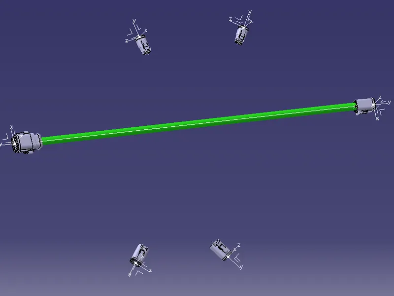 .
.
Since there is a single routing, now I have create branches. To do so I have to create branching points and then create the branches. As it is the single wire will not allow direct branching unless I designate point on the main wire routing for branch routing. There is a commod Add branch point. Using this I create branch point. When the command is selected a window opens as seen below
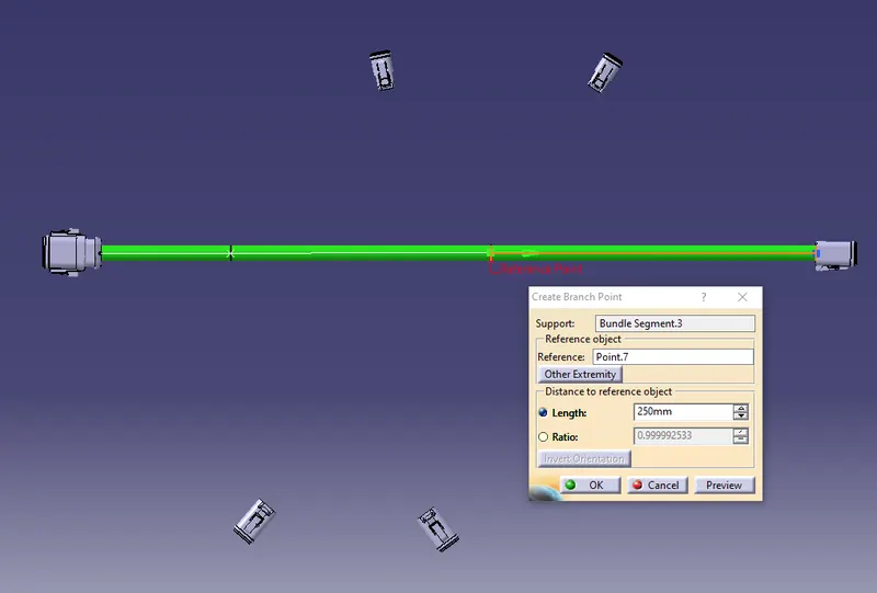
In this window it asks for reference point from which reference the wire has to be slit either in ratio or distance. Tthe option is where to provide the breaking point for branching. It can be ratio of total length or destance from one particular reference. I select the option length and select 100 from the connector point of DT06-8S and select ok. The wire is cut at that point. Next again one more branching point break is created in the routing bundle at a distance from 200mm from the previous break point. With this one more break in the total length is created.
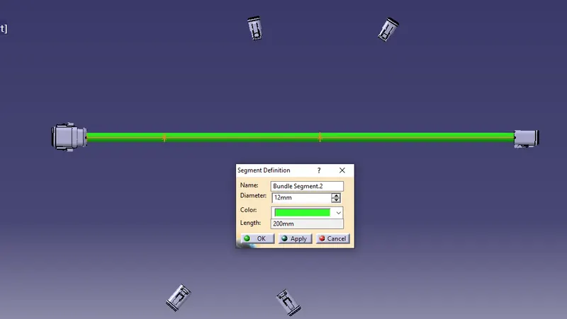
After the branching points I go to the next command branch definition. In this command It creates branches between two points which we select. In the picture below, I add a branch between the first branch point of main routing to the connector DT06-4S and I consider the routing diameter of 10mm between these two points. Only two parameters selected in the window one is diameter and second the route definition where i select first point the branch termination point and second the connector branch entry point. Once selected ok the branch looks as seen below picture.
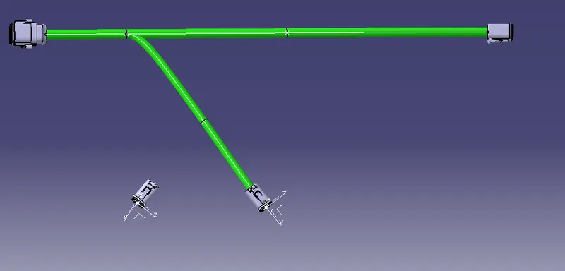
Next I add a branching point on the branch which was created now, at a distance of 150mm from the connecting point of main branch. The branch is split at 150mm from the branch termination point as seen above. Now I add one more branch of diameter 8mm from this split point to the DT06-4S connector placed at its position. The diameter is set 8mm as 4 wires terminate from this point and all other setting parameters remain same and the branch is created as seen below picture.
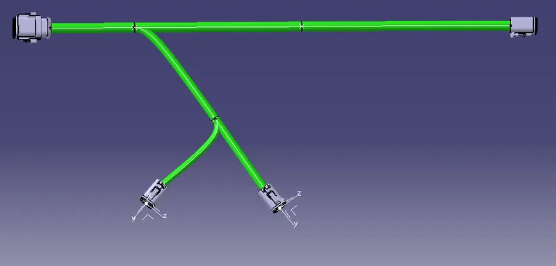
Next I move to the second split point on the main routing. I add a branch from the main branch at point of split and the connector DT04-2S. Since the wire terminated is only two I prefer 8mm routing bundle diameter and select the point on the main branch at the split edge and then other end point is terminal bundle entry point. The branch is created as seen below.
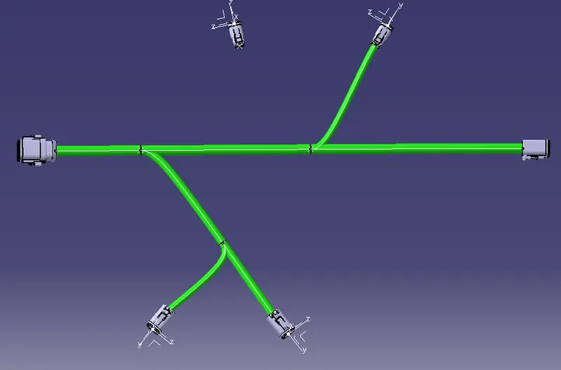
Next I add one more bracch at the split of the main bundle where I terminated one branch for DT04-2S. Again this branch is for DT04-2S and so I prefer 8mm wire diameter. The termination for routing is first point is the main bundle split point and second is the DT04-2S connector. The branch is created as seen below.
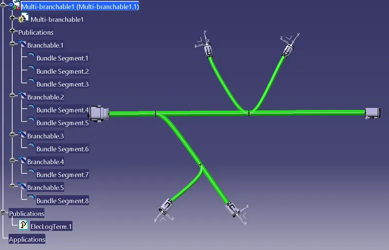
With this the bundle routing for all the connectors as given in the sketch is completed. Now I will add protective cover. I bundle the wires by using insulation tapes and then use cot tube for outer covering. It is mentioned that the protective covering is for the branches of connector DT06-2S and DT06-4S. So we add only to these branches
In the Electrical Harness Assembly platform I use the command protective covering. When I select the command a window opens. In the window first is select protective covering. I select catalogue symbol next to the box. Another window opens catalogue browser. It asks for the protective cover selection from the file saved in the destination folder. I select PVC tapes and the second window closes. Then I go to previous window where I select the bundle segmet4 and 5. Once the segment is selected I select start extremity and end extremity and set both to 25mm. Next there are other opions like layer number, Tapping angle, overlapping. I leave these option in default selection and press ok. The Insulation is created on segment 4&5 as seen below which is in blue colour.
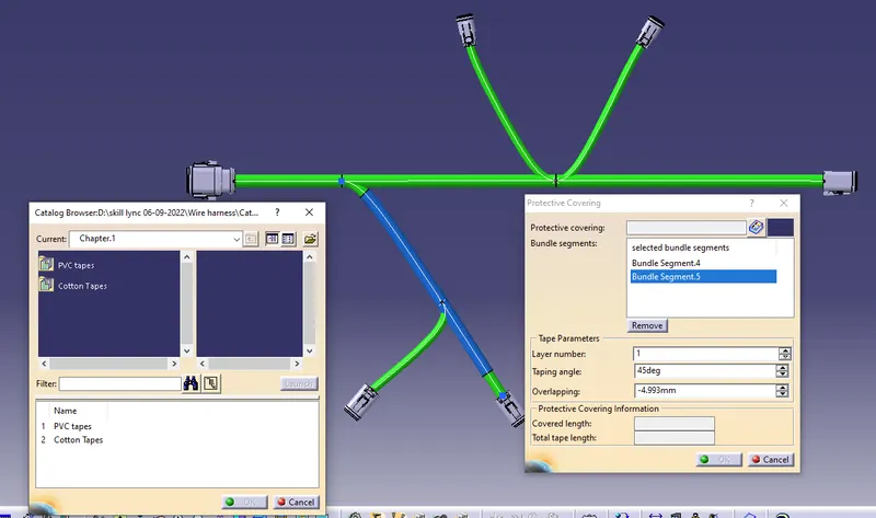
In the same I complete the insulation covering on all the branch segments and the picture is as seen below.
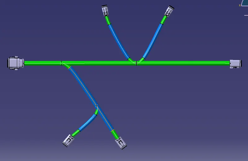
With this the insulation is complete. Next I go for protective covering which is corrogated tube or COT tube.
For creating corrogated tubes around the routing, we select the command potective covering command. There I have options in the catalogue for selecting protective covering. PVC tapes or COT tubes. I select COT tubes. Then there are varieties of COT tube in the catalogue. The varieties are sizes in diameter. The COT tube catalouge has different size like 5mm, 10mm, 15mm, 20mm, 35mm as seen in the window below.
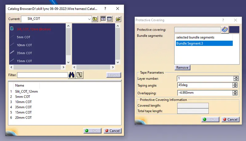
I select the size based on the OD of out routing diameter+ insulation covering. If the routing diameter is 10mm and insulation is 1mm each side which makes the total diameter 12mm. Here I use 15mm, then I select the segments which require the protective covering. These are the same segment which we have insulated. I follow the same sequence as used to create the insulation tape covering and the window and option are same. So I select the end extremity and start extremity at 30mm as specified and select OK. The cot tube is created as shown below.
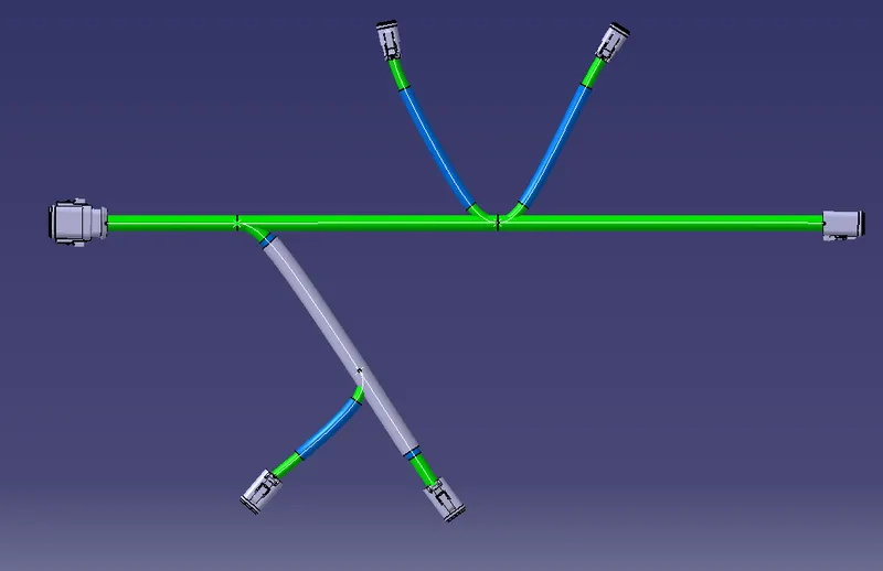
Next I do the protective covering to all the branches where I have done the Insulation taping and the picture looks as below. I use the 15mm COT tube as this is the only size suitable in my case. I cannot use 10mm as this OD is lesser than the COT tube ID and it shows error. Next size to 10mm is 15mm so this suits to all the bundle diameters.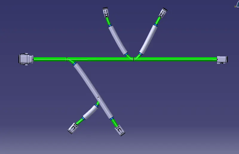
With this the challenge is complete.
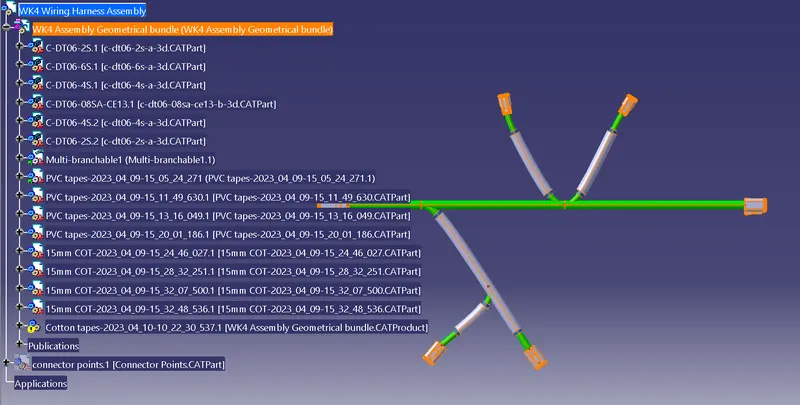
The Tree structure looks as seen in the pictue above.