Week 8 - Challenge 1 - Base Bracket Design
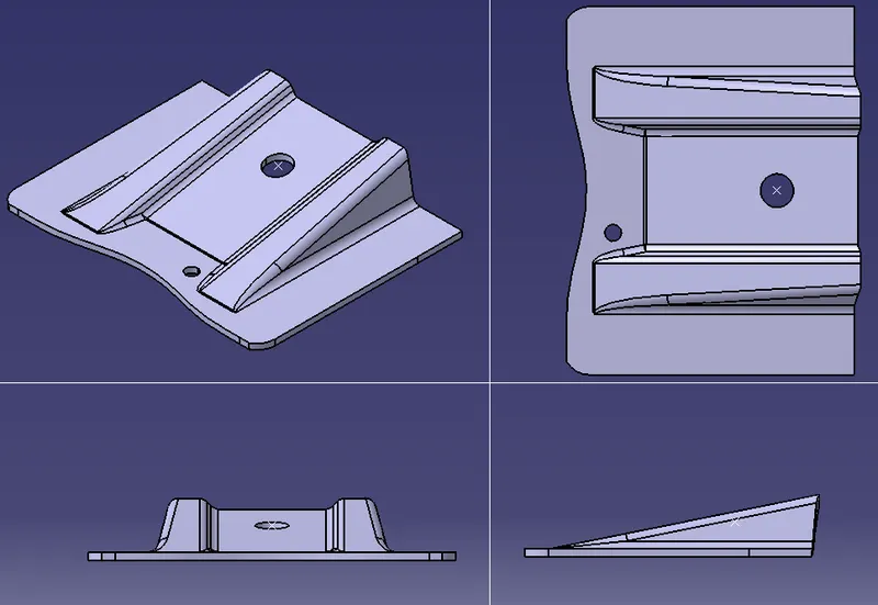
Challenge is to create plastic component with given Class A surface.
also to generate tooling axis and draft analysis.
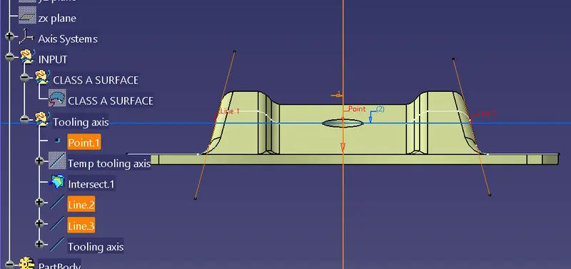
First the generation of tooling axis
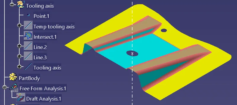
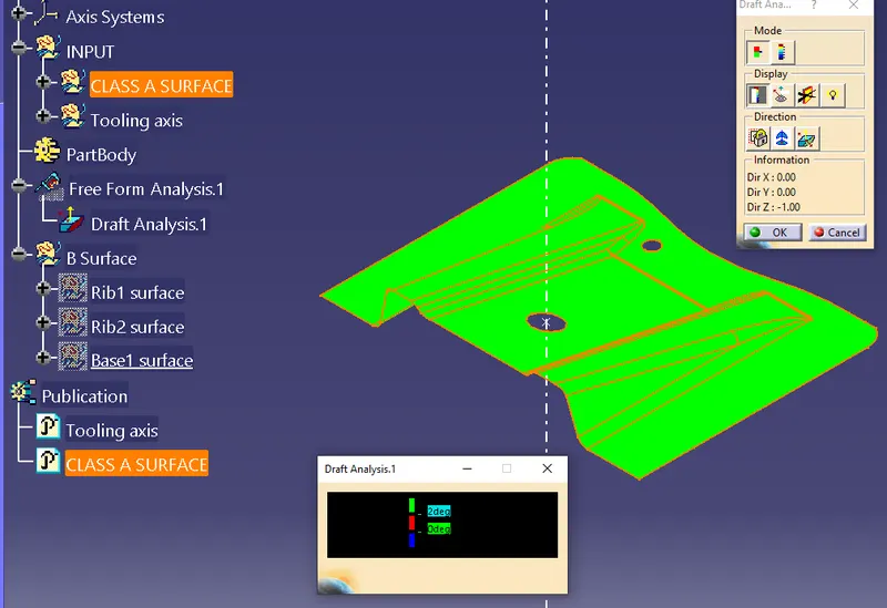
Next draft analysis with respect to tooling axis.
Here only the one axis is considered for draft analysis as the other two axis is not feasable practically.
Tooling axis
The main criteria for deciding the tooling axis, is to check the part or surface with the concept of injection molding process and tool construction. If the part is to be produced by injection molding process, the tool opens at the parting line, the surface between the core and the cavity close. The axis of opening is in a straight line and the part has to release during this movement.
Draft analysis is always done on the side wall or side surfaces. These walls to have atleast 3 degrees of clearence/taper so that when the material packed molding tool opens at the parting line of core and cavity, there must be smooth opening of tool as well as the part in between the core and cavity.The must not get damaged while opening and once the tool is open, the part must also be ejected from the core with out distortion. Considering these points there is always draft provided on the core and also on cavity side walls. The draft analysis on class A surface normally help us to understand in taking decision on going ahead with mold part with the view on how the molding tool be constructed and how parts can be produced.
The procedure followed in the part design is that we normally take section or create lines on the sidewall reference and then create a bisecting line with reference to the two lines. This is normally done in both Xplane section which we consider as x tooling axis and Y plane section as y tooling axis. The common or bisecting line generated from the x plane tooling axis and y plane tooling axis will be master or final tooling axis.
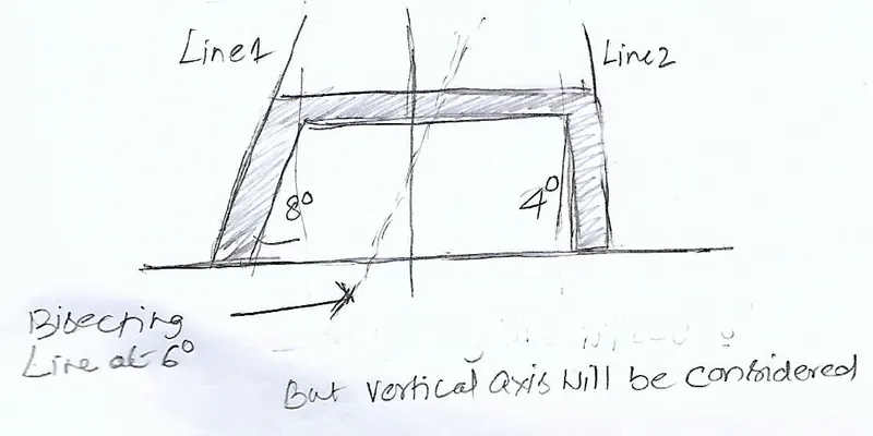
Suppose there is a square box type part or component of plastic, with two opposide side walls with 5deg angle on x plane and 8deg angle on y plane. The x bisecting line of side walls will form the x tooling axis and similarly the y bisecting line of side walls will form the y tooling axis. Finally the bisecting line generated between the two is the tooling axis. Suppose in the above case if we consider one side the wall is 4deg angle and the second wall is 8deg angle in this case the vertical axis can be considered as the tooling line instead of the bisecting line.
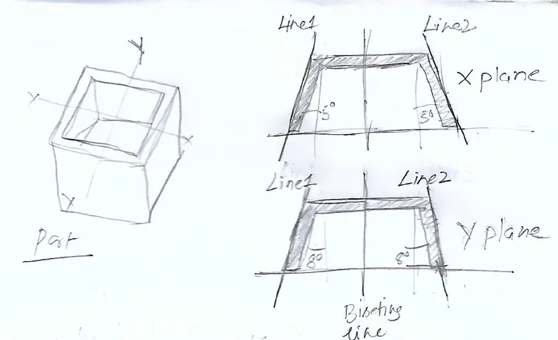
In the below case the bisecting line cannot be considered as tooling line instead the vertical axis is considered and the minimum 3deg criteria is taken care. In some case the parting line or the horizantal surface of the mold construction is given priority.
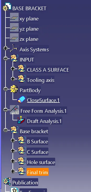
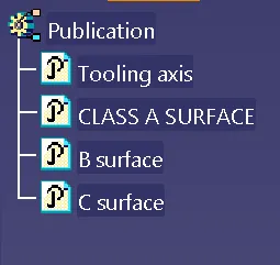
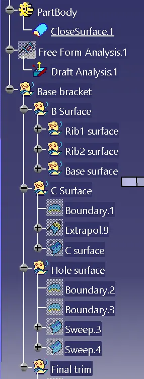
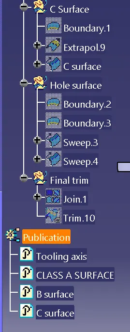
Below the pictures of part close surface and tree structure