Wiring harness design in CATIA V5 - 3D modeling Week 5 & 6 Challenge
Challenge is to download connectors and convert them into electrical part and then do the routing as per the sketch shown. Create two harness routing and connect both with connector.
The connectors numbered in series against which I select the connectors as mentioned in the list below
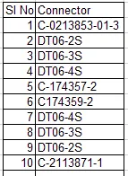
Down loaded all the connectors and opened it in catia saved it as catpart and created connector connectingpoint, connector connecting axis and bundle entry point on all the connector and saved it. Then opened the same part in electrical part design environment and defined each connector as electrical part-connector. Then defined the connector connecting point, reference point, coincidence axis, reference axis, bundle entry points in all the connectors and saved in one directory.
The connector planning is as below.
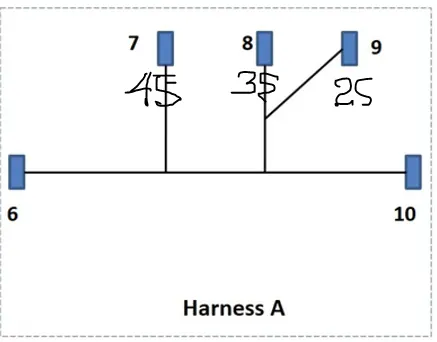
Position of connectors in A routing.
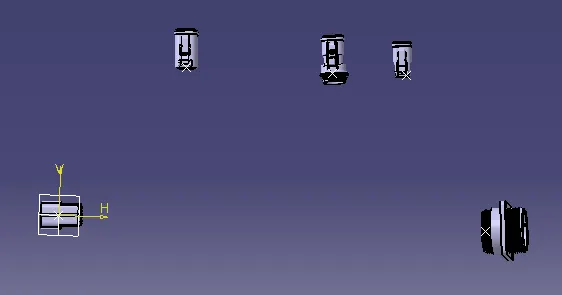
 +
+
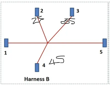
Position of connectors in B routing.
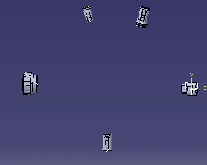
Created two product file in catia. Harness A Routing and Harness B Routing. With reference to the above details for placing of connectors, added the related connectors in both the product files. Then created a part file only for creation of points to place the connectors in position. Copied the connector points in both the files and positioned all the connectors using snap mode, smart move. Then created one more product file and named as Harness A&B assembly. Added the product file Harness A routing and Harness B routing files in the A&B assembly file.
In the A&B product file I positioned the pin connector from A routing and receptle connector from B routing together in connected position and then started working in the individual file A & B routing. Positioned all the mentioned connectors in position as shown in the above pictures.
Next I start routing
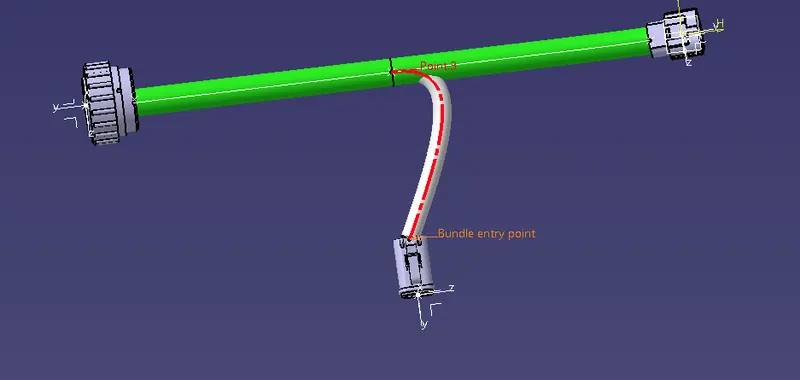
This error was corrected by moving the connector position slightly. First I tried by changing the slack option by changing the slack% by 5,10,20,30. But has no result. So I changed the position and the problem was solved.
Next branching of other connectors was completed with out any issues and the picture is as below.
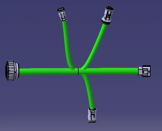
This completes the Routing of B side Harness.
Next we start A side harness routing. I open the file in which I have already placed all the connectors in position. First I connect the main two connector which is the main branch with 15mm diameter. On this Main branch I split at two places to create two branches.
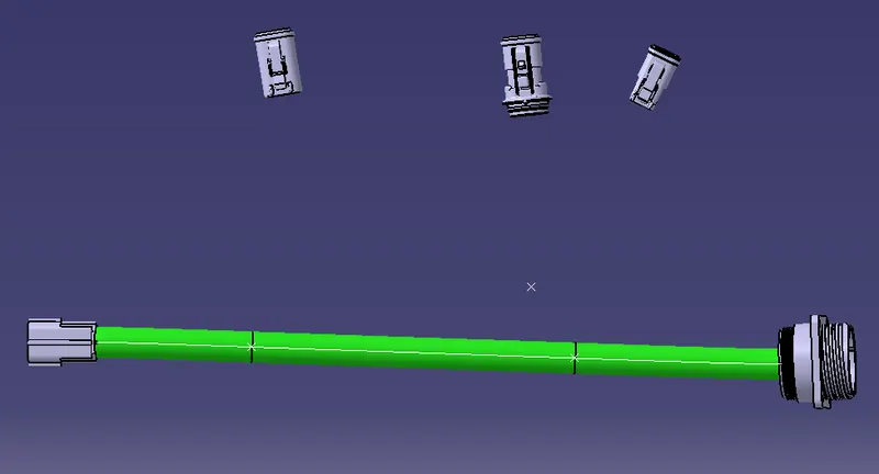
Next I create branches from the slit point of the main branch and to the connectors positioned above. Here I change the diameter to 8mm, 10mm and 5mm.
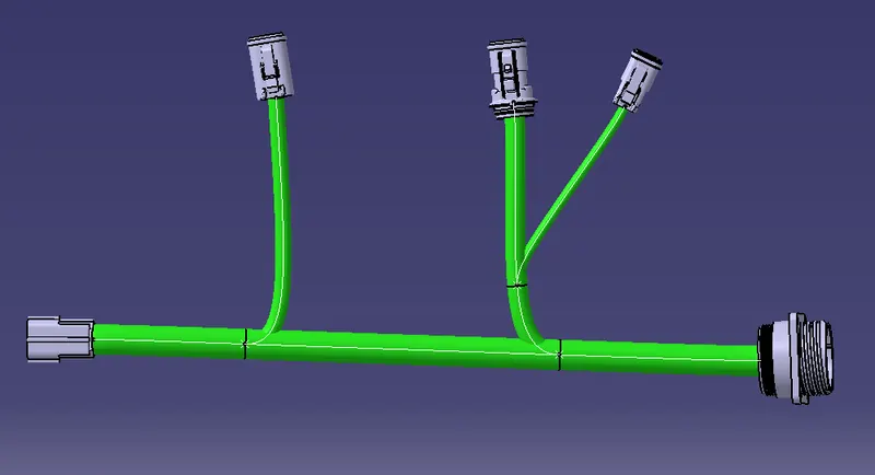
This completes both the routing. Since the main A & B connecting connectors was positioned in connected condition so there is no necessary for again providing the connection.
Next first I check the continuity of the A. I select the command Edit and then go to search a window opens as seen below and in the first option of work bench I select Electrical and in the next option type I select Bundle segment and in the final option Attribute I select fully connected option. Then a window pops asking for attribute condition "Electrical Bungle Segment Fully Connected" and we have two option to be selected. True and False. I select True and check the continuity.
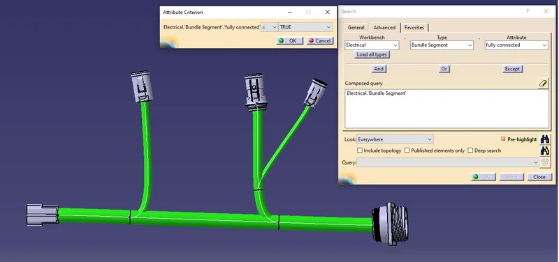
After selecting True option I select the option search.
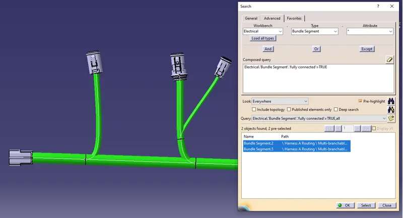
I get the above error. Now I start editing the routing. I delete the branches first and again recreate them and after recreating I again do the continuity check analysis and the result is as below. One of the bundle segment bundle segment 18 is seen as not connected.
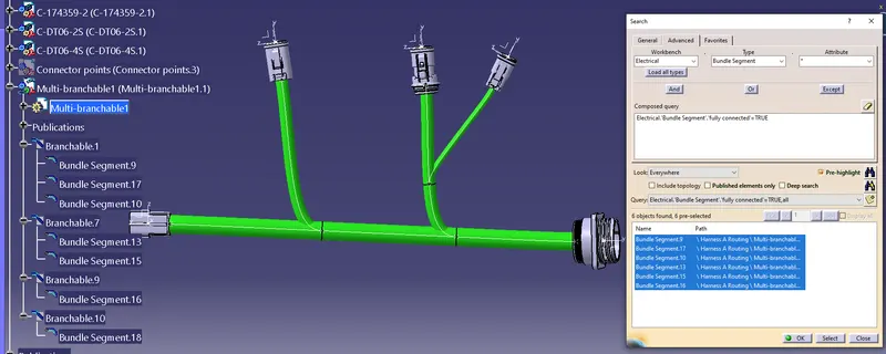
I cross check the above result with false condition and see one segment is not connect as seen below in false condition.
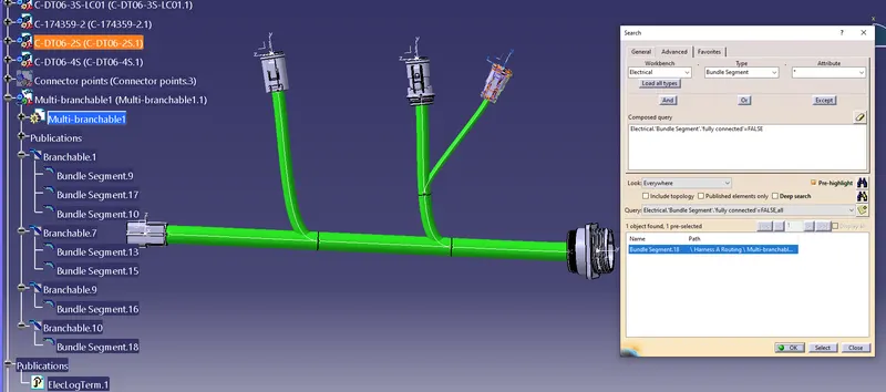
I again try to re-route this branch but see no result so I delete this particular branch and do routing it again
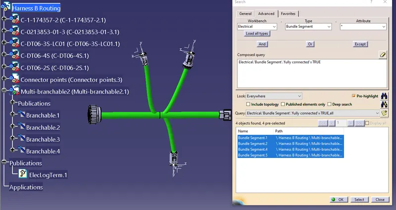
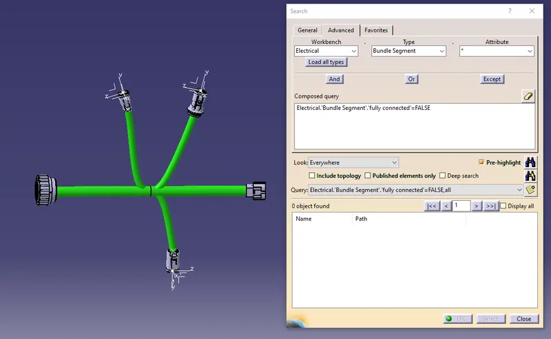
In case of the Harness B routing when I check the continuity, I get the OK message. In True condition I seel all the branchable segments are shown as connected. To cross check I use option false and redo the analysis and I find ok as seen in below picture. No segments as listed in false condition.
Even after creating new route between the connector and the split main branch I find the error exist. I try checking the by removing the branch point and creating new branch point I still get the same error. When I check the routing connection it showed point connection so I opened the connector electrical point definitions and see that there is no branch entry point defined on this connector but see a point created in that area. So I open the connector in electrical part environment and define the bundle entry point which is already created on the connectorl.
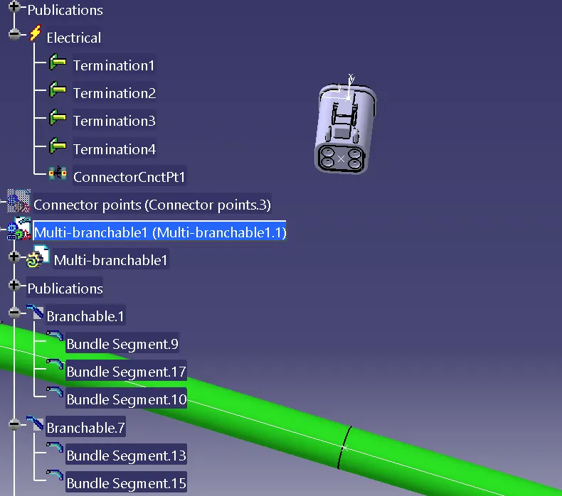
Now I do the routing between the connector and the split point on the main bundle. After I do the continuity analysis and see that the result of all segment connected in true condition as seen in below picture.
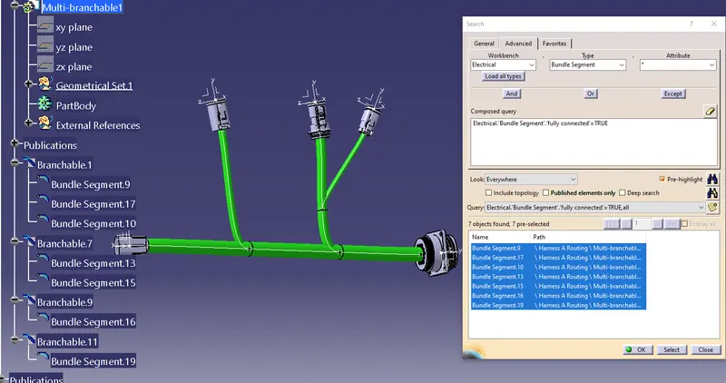
I cross check the same with false condition and the result is as seen below.
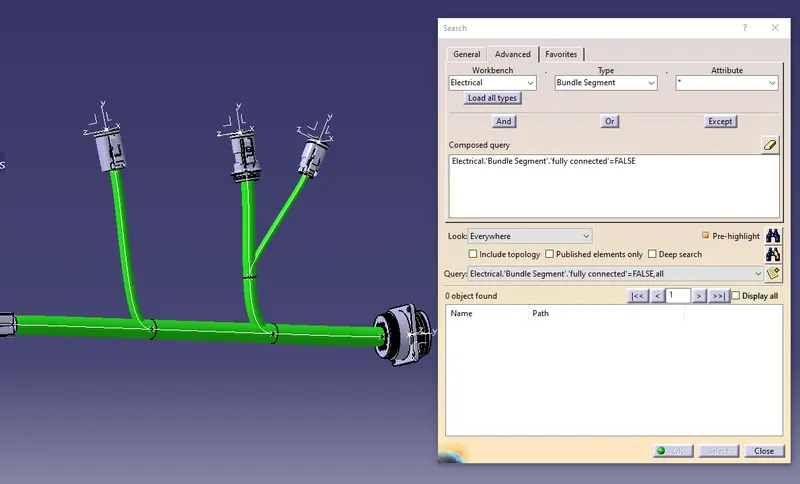
After solvind harness A routing, I go to harness B routing for continuity checking analysis. I do not find any errors and the result is as seen below in both true and false condtion.
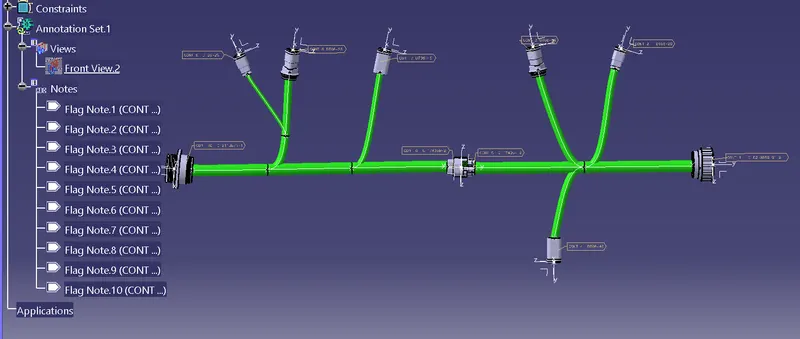
Next I add annotation for the connectors. I used the command insert-annotation-flag note-flag note with leader and created the flag notes of the connector as seen in below picture.
Finally I convert the assembly into iges formant and save it in same folder.
This completes the challenge.