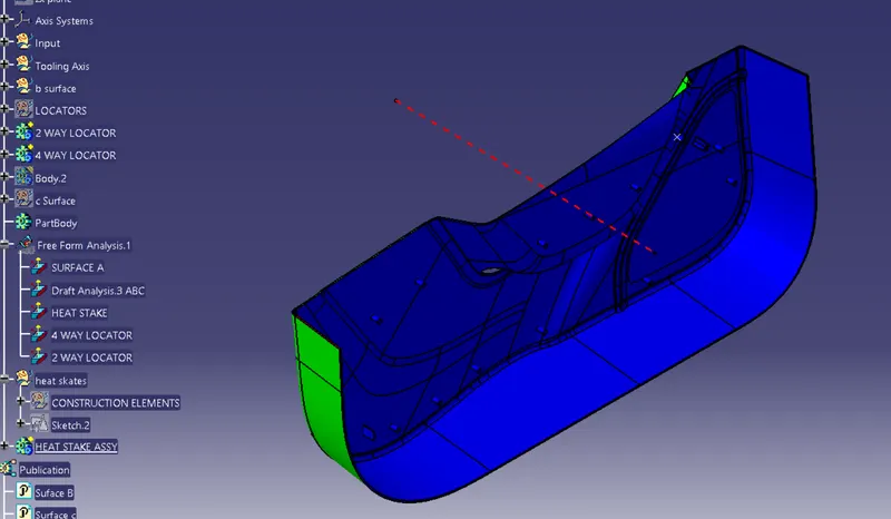
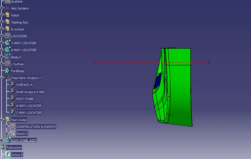
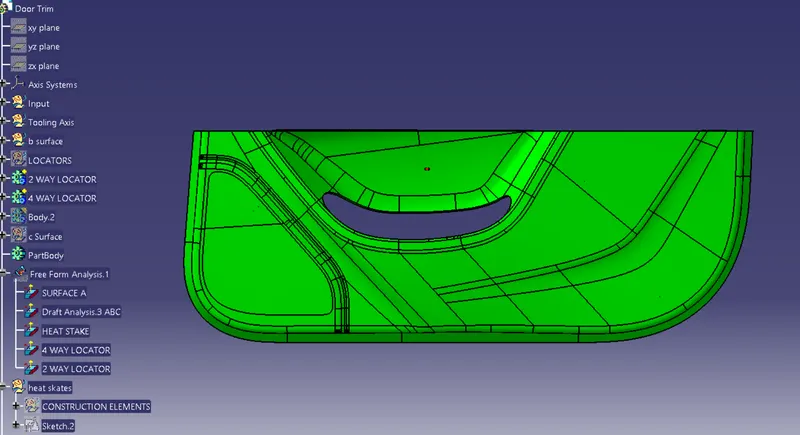
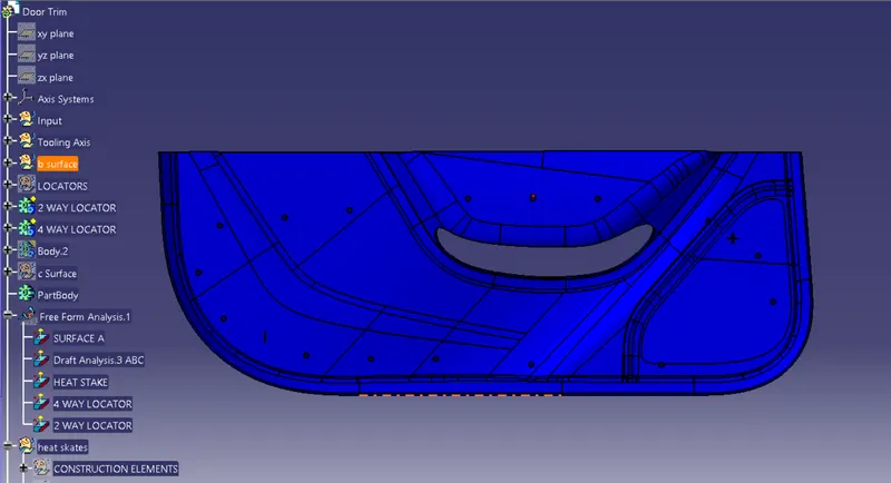
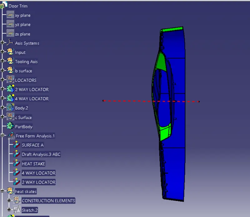
Week 9 - Project 1 - Door Trim Lower with Engineering Features
AIM
Create the Door Trim Lower Plastic component through the given Class-A surface. To begin with, the tooling axis for the given Class-A Surface should be created meeting the requirements of the draft angle and at the end perform the Draft analysis on the model.
Create the Heat Stakes and the locators considering the design rules mentioned
THEORY
What is Draft Analysis
The draft analysis technique is used to analyze whether our part model created in CAD is manufacturable based on the draft condition applied. Here the part should get easily removed from the panel dies (in case of Sheet metal part) or Mold (in case of plastic).
The draft analysis command enables us to detect if the drafted part can be easily removed. This type of analysis is done based on the colour ranges identifying the zones on the analysed element where it makes a deviation from the normal values.
Draft
For molded or cast parts, the draft angle is the amount of taper perpendicular to the parting line. It is measurable in degrees. Because plastic shrinks and sticks on molding surfaces as it cools, for molded or cast parts, the draft angle is the amount of taper perpendicular to the parting line. It is measurable in degrees. Because plastic shrinks and sticks on molding surfaces as it cools, we draft the walls of the plastic part so that it ejects or breaks free from the molding surfaces more easily and without dragging. To reduce the risk of damage to the parts and ensure ejection, a functional injection molding part must have drafts on both the cavity and core sides.
Draft Angle Guidelines
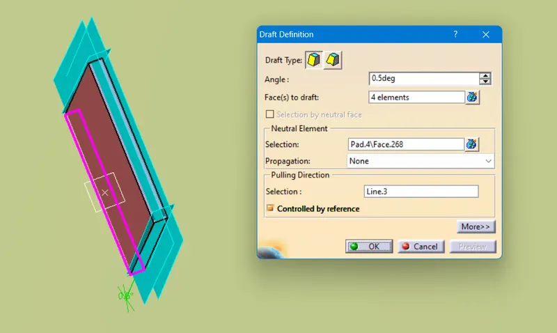
- `0.5^o`degrees on all vertical faces
- `1^o-2^o` works very well in most situations
- `3^o` is the minimum for a shutoff
- `3^o` is required for light texture
- `5^o` or more is required for heavy texture
Tooling Axis Creation
Tooling direction is the main consideration for the plastic part and the mold parts because it defines the movement of the mold part and the possibility of the plastic part coming out from the mold part (core & cavity). Tooling direction is critical for plastic product design because it determines mold direction
Steps Involved
- a reference point is created on the extracted surface.
- a new axis system is used to plot the extracted surface
- The x and y axis were used to develop the tooling axis using the Intersection curve
- The two clearing lines were bisected to form the Tooling axis,
- The tooling axis's graphic properties are changed to identify the Tooling axis
Design Consideration
- Class – A surface should be aesthetically smooth and good.
- Class – B surface should have all the supporting features like ribs.
- The parting line should coincide with the B surface since flashing couldn’t affect the aesthetic of Class – A.
- Class – C surface should also pass the draft analysis.
HEAT STAKES
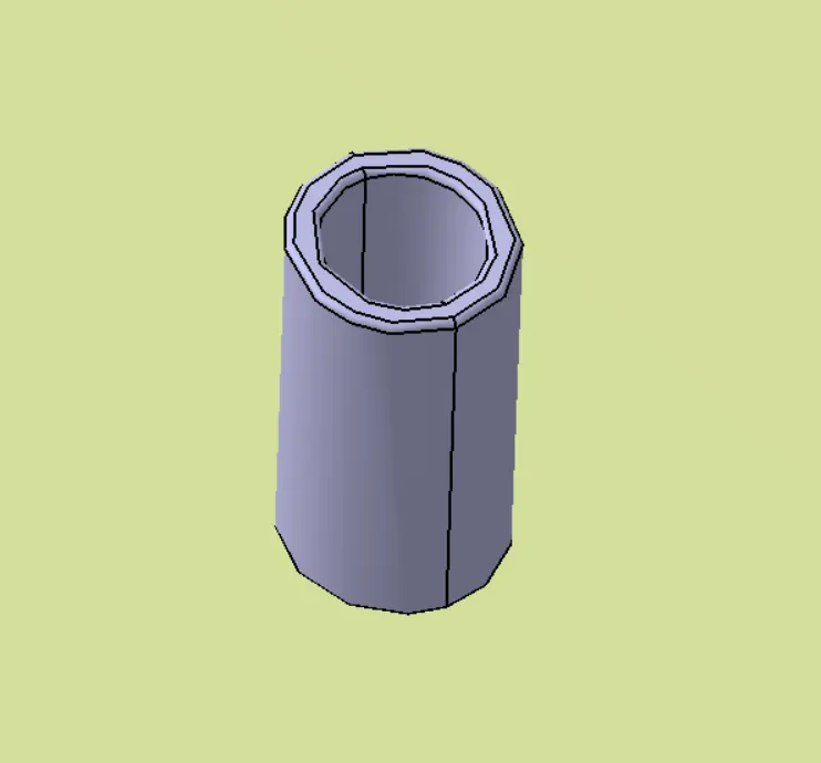
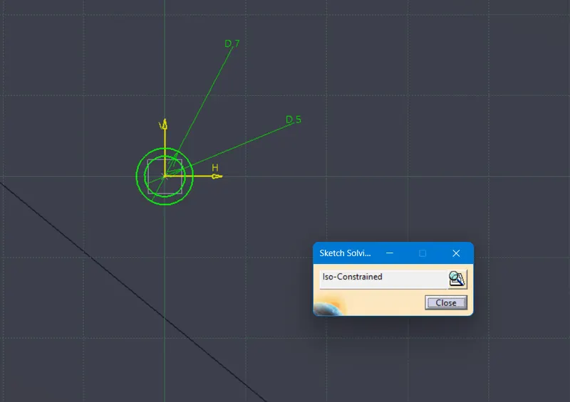
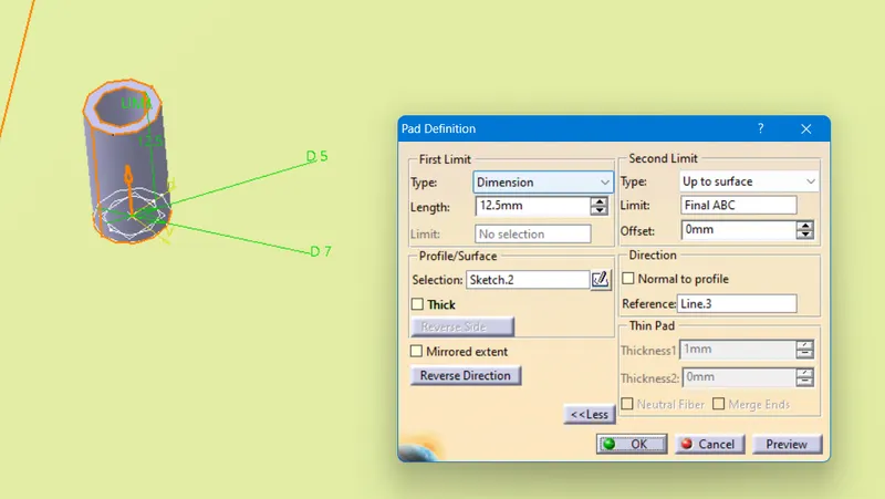
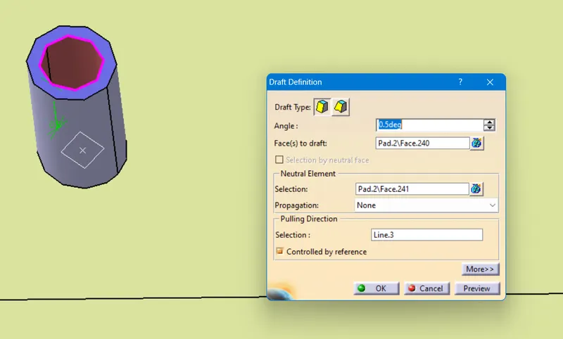
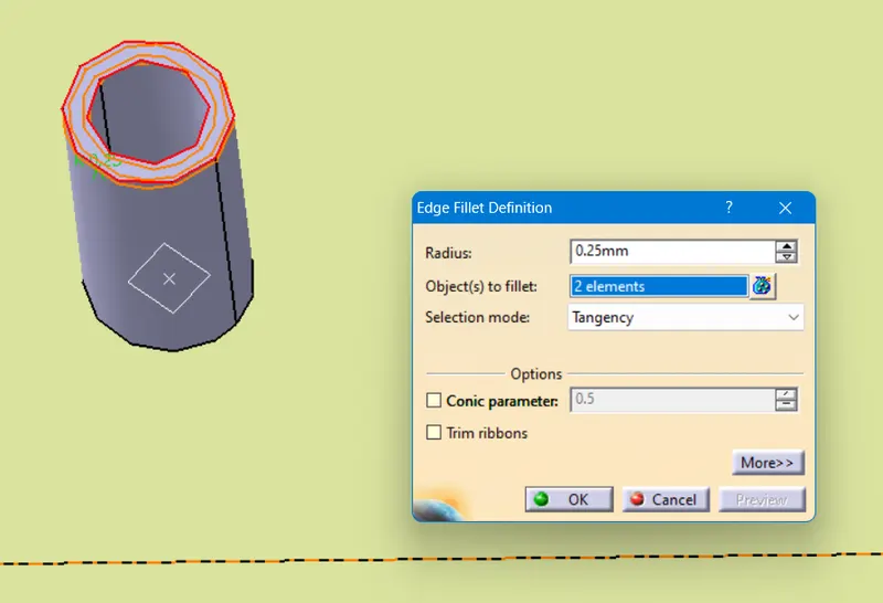
Heat staking also known as thermoplastic staking is the process of joining two dissimilar materials together. In heat staking, we use local heating and cooling to raise the temperature of plastic components and allow plastic reforming to be carried out. This reform can be used in a wide variety of applications.
Heat staking can be done with a precise and rapid operation that also offers repeatable results every cycle. A manufacturing machines can be developed to complete multiple heat-staking operations at once to decrease cycle time. The stakes don’t have to be parallel which makes the design options limitless.
Heat staking is a great option that is comparable in strength and durability to other operations involving secondary fasteners without extra cost. These connections can also resist corrosion in harsh environments.
 |
 |
 |
 |
LOCATORS
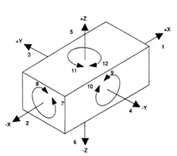
The 3-2-1 method is a work-holding principle where three pins are located on the 1st principle plane, i.e., either XY, YZ, ZX. And two pins are located on the 2nd plane perpendicular to the 1st plane, and at last, one pin on the plane is mutually perpendicular to the 1st and 2nd planes. The aim is to constrain the movement of the workpiece along all three axes.
4 Way Locators
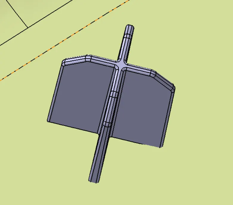 |
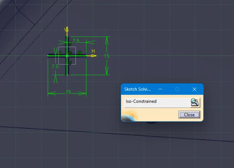
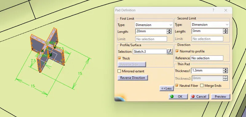
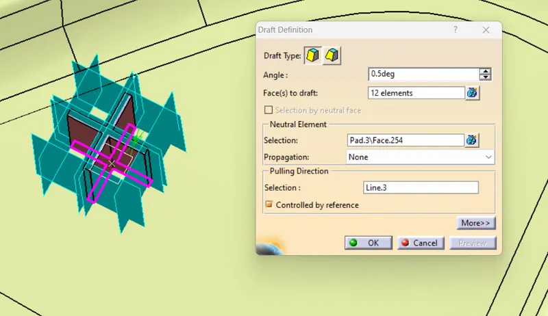
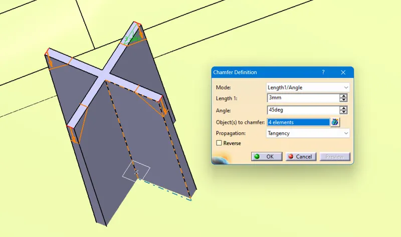
4-way means you prevent movement at 2 axis (+X, -X, +Y and -Y) on the plane. Generally, you have a cylindrical pin on the fixture and a circular hole at the workpiece part.
 |
 |
 |
 |
2 Way Locators
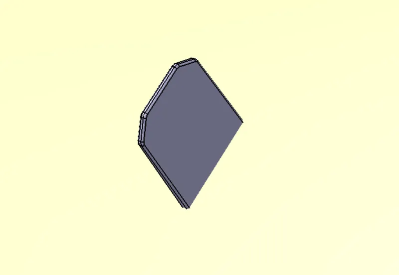 |
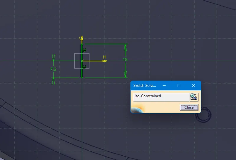
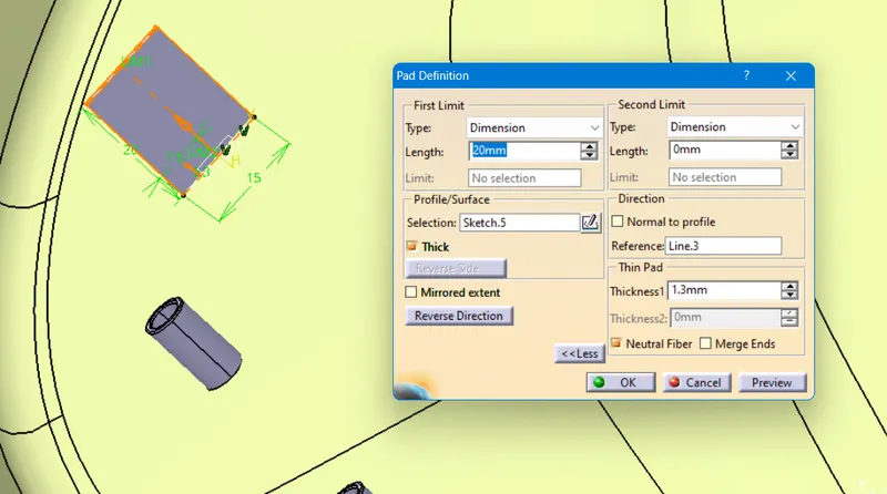
2-way means you prevent movement only at 1 axis on the plane. And generally, you have a cylindrical pin on the fixture and a slot hole at the workpiece part.
 |
 |
 |
 |
FINAL