Project-1: Powertrain for aircraft in runways
1. AIM
To design a Powertrain for aircraft in runways
2. OBJECTIVE
- Search and list out the total weight of various types of aircraft.
- Is there any difference between ground speed and airspeed?
- Why is it not recommended to use aircraft engine power to move it on the ground at the Airport?
- How an aircraft is pushed to the runway when it's ready to take off?
- Learn about take-off power, tyre design, rolling resistance, tyre pressure, brake forces when landing.
- With necessary assumptions, calculate the force and power required to push/pull an aircraft by a towing vehicle.
- Design an electric powertrain and draw a block diagram of the powertrain.
3. THEORY
3.1 Search and list out the total weight of various types of aircraft.
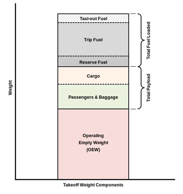
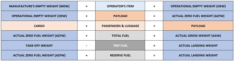
The aircraft gross weight (also known as the all-up weight and abbreviated AUW) is the total aircraft weight at any moment during the flight or ground operation.
An aircraft's gross weight will decrease during a flight due to fuel and oil consumption. An aircraft's gross weight may also vary during a flight due to payload dropping or in-flight refuelling.
|
|
 |
List of some of the aircrafts.
|
Type |
MTOW [kg] |
MLW [tonnes] |
TOR [m] |
LR [m] |
ICAO category |
FAA category |
|
Antonov An-225 |
640,000 |
591.7 |
3500 |
Heavy |
Super |
|
|
Scaled Composites Model 351 Stratolaunch |
589,670 |
3660 |
Heavy |
Super |
||
|
Airbus A380-800 |
575,000 |
394 |
3100 |
1930 |
Super |
Super |
|
Boeing 747-8F |
447,700 |
346.091 |
3100 |
1800 |
Heavy |
Heavy |
|
Boeing 747-400 |
396,900 |
295.742 |
3018 |
2179 |
Heavy |
Heavy |
|
Lockheed C-5 Galaxy |
381,000 |
288.417 |
2530 |
1494 |
Heavy |
Heavy |
|
Boeing 747-200 |
377,840 |
285.700 |
3338 |
2109 |
Heavy |
Heavy |
|
Boeing 747-300 |
377,840 |
260.320 |
3222 |
1905 |
Heavy |
Heavy |
|
Airbus A340-500 |
371,950 |
240 |
3050 |
2010 |
Heavy |
Heavy |
|
Airbus A340-600 |
367,400 |
256 |
3100 |
2100 |
Heavy |
Heavy |
3.2 Is there any difference between ground speed and airspeed?
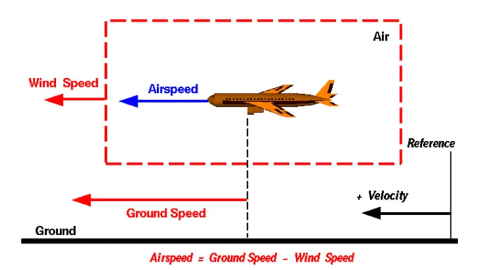
To properly define the relative velocity, it is necessary to pick a fixed reference point and measure velocities relative to the fixed point. In this slide, the reference point is fixed to the ground, but it could just as easily be fixed to the aircraft itself. It is important to understand the relationships of wind speed to ground speed and airspeed.
 |
Wind Speed:
For a reference point picked on the ground, the air moves relative to the reference point at the wind speed. Notice that the wind speed is a vector quantity and has both a magnitude and a direction. The direction is important. A 20 mph wind from the west is different from a 20 mph wind from the east. The wind has components in all three primary directions (north-south, east-west, and up-down). In this figure, we are considering only velocities along the aircraft's flight path. A positive velocity is defined to be in the direction of the aircraft's motion.
For a reference point picked on the ground, the aircraft moves relative to the reference point at the ground speed. Ground speed is also a vector quantity. So a comparison of the ground speed to the wind speed must be done according to rules for vector comparison.
Airspeed:
The important quantity in the generation of lift is the relative velocity between the object and the air, which is called the airspeed. Airspeed cannot be directly measured from a ground position but must be computed from the ground speed and the wind speed.
Airspeed = Ground Speed - Wind Speed
3.3 Why is it not recommended to use aircraft engine power to move it on the ground at the Airport?
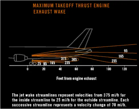
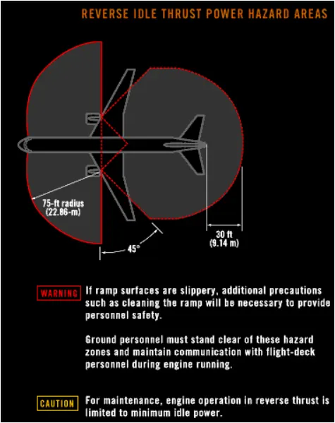
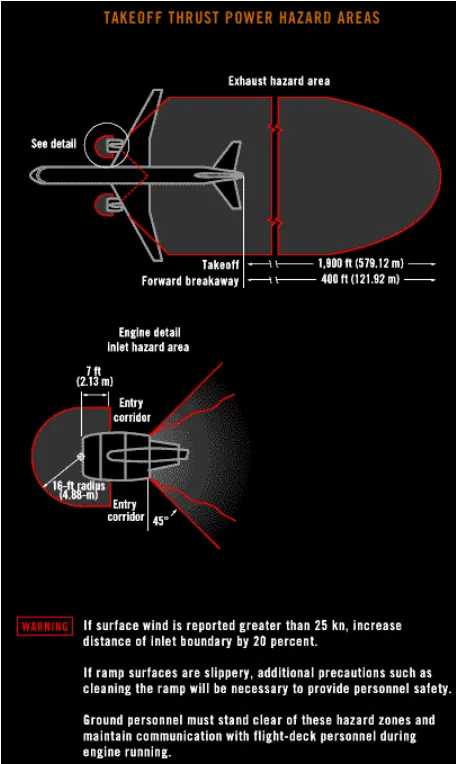
The risks which may arise from engine ground running related to the potential for loss of control of the aircraft by the pilots. In most cases, such people will be maintenance personnel holding specific company-issued approval for the required tasks. The consequences of loss of control during taxi or towing are the same as applying these operations generally and this article is concerned only with the risks arising from the static running of one or more aircraft engines. Unwanted consequences from such static running are mainly related to those arising from the unintended movement of the aircraft during engine running - effectively a loss of control - especially during high power engine running. Damage can occur to the aircraft itself, other aircraft nearby or to airside structures. In addition, there is a risk of injury to ground support personnel who may be in relatively close proximity to the aircraft.
The exhaust wake from these engines can pose hazards in commercial airport environments. Operators and airport authorities must carefully consider these hazards and the resulting potential for injury to people and damage to or caused by baggage carts, service vehicles, airport infrastructure, and other aeroplanes. High engine thrust during maintenance activity can cause considerable damage to airplanes and other elements in the airport environment.
 |
 |
 |
3.4 How an aircraft is pushed to the runway when it's ready to take off?
In aviation, pushback is an airport procedure during which an aircraft is pushed backwards away from an airport gate by external power. Pushbacks are carried out by special, low-profile vehicles called pushback tractors or tugs.
Although many aircraft are capable of moving themselves backwards on the ground using reverse thrust (a procedure referred to as a powerback), the resulting jet blast or prop wash might cause damage to the terminal building or equipment. Engines close to the ground may also blow sand and debris forward and then suck them into the engine, causing damage to the engine. A pushback is therefore the preferred method to move the aircraft away from the gate.
Pushbacks at busy aerodromes are usually subject to ground control clearance to facilitate ground movement on taxiways. Once clearance is obtained, the pilot will communicate with the tractor driver (or a ground handler walking alongside the aircraft in some cases) to start the pushback. To communicate, a headset may be connected near the nose gear.
Since the pilots cannot see what is behind the aircraft, steering is done by the pushback tractor driver and not by the pilots. Depending on the aircraft type and airline procedure, a bypass pin may be temporarily installed into the nose gear to disconnect it from the aircraft's normal steering mechanism.
Once the pushback is completed, the towbar is disconnected, and any bypass pin removed. The ground handler will show the bypass pin to the pilots to make it clear that it has been removed. The pushback is then complete, and the aircraft can taxi forward under its own power.
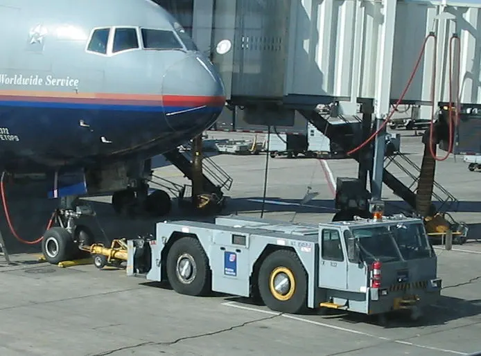
Large aircraft cannot be moved by hand and must have a tractor or tug. Pushback tractors use a low profile design to fit under the aircraft nose. For sufficient traction the tractor must be heavy, and most models can have extra ballast added. A typical tractor for large aircraft weighs up to 54 tonnes (59.5 short tons; 53.1 long tons; 119,000 pounds) and has a drawbar pull of 334 kN (75,000 lbf). Often the driver's cabin can be raised for increased visibility when reversing and lowered to fit under aircraft. There are two types of pushback tractors: conventional and towbarless (TBL).
Conventional tugs use a tow bar to connect the tug to the nose landing gear of the aircraft. The tow bar is fixed laterally at the nose landing gear, but may move slightly vertically for height adjustment. At the end that attaches to the tug, the tow bar may pivot freely laterally and vertically. In this manner the tow bar acts as a large lever to rotate the nose landing gear. Each aircraft type has a unique tow fitting so the towbar also acts as an adapter between the standard-sized tow pin on the tug and the type-specific fitting on the aircraft's landing gear. The tow bar must be long enough to place the tug far away enough to avoid hitting the aircraft and to provide sufficient leverage to facilitate turns. On heavy tow bars for large aircraft the towbar rides on its own wheels when not connected to an aircraft. The wheels are attached to a hydraulic jacking mechanism which can lift the towbar to the correct height to mate to both the airplane and the tug, and once this is accomplished the same mechanism is used in reverse to raise the tow bar wheels from the ground during the pushback process. The tow bar can be connected at the front or the rear of the tractor, depending on whether the aircraft will be pushed or pulled. The towbar has a shear pin which prevents the aircraft from being mishandled by the tug; when overstressed the shear pin will snap, disconnecting the bar from the nose gear to prevent damage to the aircraft and tug.
 |
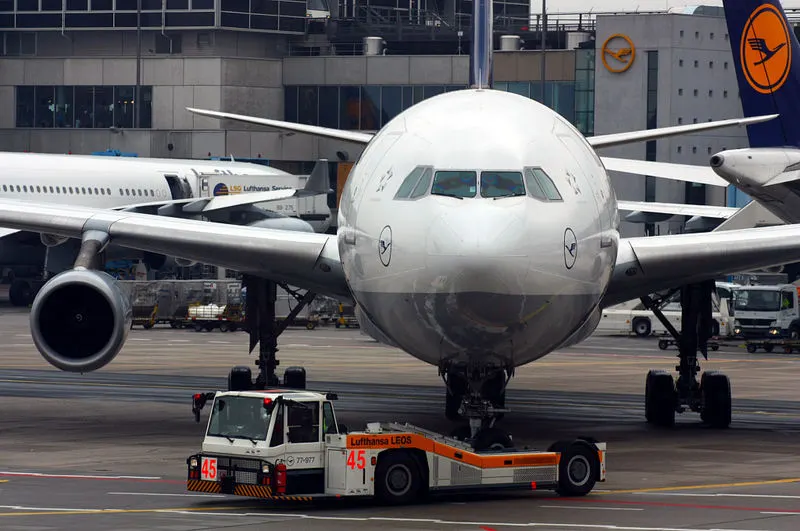
Towbarless (TBL) tractors do not use a towbar; they scoop up the nose landing gear and lift it off the ground. This avoids the time penalty of connecting/disconnecting a towbar, and entirely removes the cost/complexity of maintaining towbars on the ramp. The tug itself does not need to be particularly massive - the aircraft's nosewheel weight provides the necessary downward force. Lastly, a TBL tug is much shorter (compared to a tug+towbar system) and has one only a single pivot point instead of one at either end of the towbar, so it has much simpler and precise control of the aircraft. This is very useful in general aviation settings with a wider variety of aircraft in more confined spaces than their airline counterparts.
 |
3.5 Learn about take-off power, tyre design, rolling resistance, tyre pressure, brake forces when landing.
Take-off power
Take-off performance can be predicted using a simple measure of the acceleration of the aircraft along the runway based on force equilibrium.
The forces involved will be,
T – Thrust of propulsion system pushing aircraft along the runway.
D – Aerodynamic Drag of vehicle resisting the aircraft motion.
F – Rolling resistance friction due to the contact of wheels or skids on the ground.
During the take-off run, the imbalance in these forces will produce an acceleration along the runway.
`(dV)/dt=(T-D-F)/m`
where `(dV)/dt` is the acceleration along the runway and m is the mass of the vehicle.
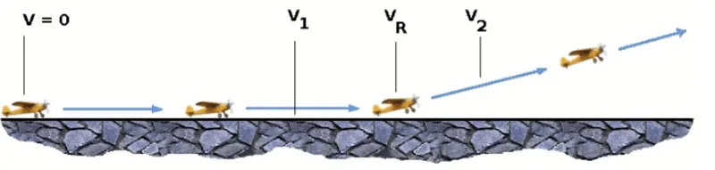 |
In the figure above,
V1 - Abort decision speed. Below this speed, the take-off can be safely aborted. After this, there will not be sufficient runway length to allow the aircraft to decelerate to a stop.
V2 - Safe climb speed. V2 must be no less than 1.2 * Vstall. Below this speed aircraft cannot attain a sufficient climb rate.
The thrust of gas turbines or turbofan engines will be relatively constant during take-off. A good assumption is to use the manufacturer's values for maximum static thrust for take-off calculations.
The thrust of a propeller-driven aircraft can be found from the given shaft horsepower data for the engine and the use of the equations using propeller efficiency.
`T=(P_(shaft)*eta)/V`
Tyre design:
Aircraft tires can easily be taken for granted. Their simplistic appearance may lead some to a false feeling of complacency. Many technicians are not aware of the critical design factors that go into every aircraft tire in use today. Seemingly minor flaws can lead to disastrous results, and inadequate maintenance practices can cause shortened tire life and even cause unsafe operating conditions.
When one considers the forces that aircraft tires endure, it seems amazing that engineers were ever able to develop these special products. Some tires are subjected to speeds as fast as a race car while at the same time supporting more weight than the largest land moving machines. They go through cyclic exposure to varying temperatures and pressures. These factors make aircraft tire design a critical process and tire maintenance an ever-important step in safe aircraft operation.
Engineers are challenged with designing tires with cool running, heat-resistant materials while simultaneously exceeding tire service requirements. Tire prototypes are put through rigorous tests that simulate cycles of landings, take-offs, and taxi operations. It is only after the tires pass all mandatory tests and meet the requirements of the aircraft manufacturer and airworthiness authorities that the tires are put into production. Two types of tires are used in aircraft applications — bias-ply tires and radial tires.
Bias-ply tires are popular choices for aircraft tires because of their durability and retreadability.
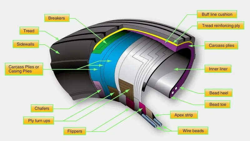 |
Tread: The tread is made of rubber mixed with other additives to obtain the desired level of toughness, durability, and resistance to wear. The tread pattern is designed to aircraft operational requirements, with the ribbed tread design used widely due to its good traction under varying runway conditions.
Sidewall: The sidewall is a protective layer of rubber that covers the outer casing ply. It extends from the tread edge to the bead area.
Tread Reinforcing Ply: One or more layers of fabric that strengthens and stabilizes the tread area for high-speed operation. It also serves as a reference for the buffing process when tires are retreated.
Buff Line Cushion: The buff line cushion is made of rubber compound to enhance the adhesion between the tread reinforcing ply and the breakers or casing plies. It is of sufficient thickness to allow for the removal of the old tread when the tire is retreated.
Breakers: Breakers are reinforcing plies of rubber-coated fabric placed under the buff line cushion to protect casing plies and strengthen and stabilize the tread area. They are considered an integral part of the casing construction.
Casing Plies: Alternate layers of rubber-coated fabric (running at opposite angles to one another) provide the strength of the tire.
Wire Beads: Hoops of high tensile strength steel wire that anchor the casing plies and provide a firm mounting surface on the wheel. The outer edge of the bead that fits against the wheel flange is called the bead heel. The inner bead edge is called the bead toe.
Apex Strip: A wedge of rubber affixed to the top of the bead bundle.
Flippers: Layers of rubberized fabric that help anchor the bead wires to the casing and improve the durability of the tire.
Ply Turnips: The casing plies are anchored by wrapping them around the wire beads, thus forming the ply turnups.
Chafer: A protective layer of rubber and/or fabric located between the casing plies and wheel to minimize chafing.
Liner: In tubeless tires, the liner is a layer of low permeability rubber that acts as a built-in tube and restricts gas from diffusing into the casing plies. In tube-type tires, a thinner liner is used to prevent tube chafing against the inside ply.
Radial tyre:
They have fewer components in their construction and are lighter than similarly sized bias-ply tires. Components that differ from bias-ply construction as follows:
Overlay: A layer of reinforcing rubber-coated fabric placed on top of the belts to aid in high-speed operation.
Belt Plies: A composite structure that stiffens the tread area for increased landings. The belt plies increase the tire strength in the tread area.
Casing Plies: As in bias-ply tires, the casing plies are layers of rubber-coated fabric. However, unlike those in bias plies that run at opposite angles to one another, radial plies run radially from bead to bead.
Chippers: The chippers are layers of rubber-coated fabric applied at diagonal angles that improve the durability of the tire in the bead area.
Tyre pressure:
An aircraft tire or tyre is designed to withstand extremely heavy loads for short durations. The number of tires required for aircraft increases with the weight of the aircraft, as the weight of the aeroplane needs to be distributed more evenly. Aircraft tire tread patterns are designed to facilitate stability in high crosswind conditions, to channel water away to prevent hydroplaning, and for braking effect.
Aircraft tires also include fusible plugs(which are assembled on the inside of the wheels), designed to melt at a certain temperature. Tires often overheat if maximum braking is applied during an aborted takeoff or an emergency landing. The fuses provide a safer failure mode that prevents tire explosions by deflating in a controlled manner, thus minimizing damage to aircraft and objects in the surrounding environment.
Each of the twelve Boeing 777-300ER main tires is inflated to 220 psi (15 bar; 1,500 kPa), weighs 120 kg (260 lb), has a diameter of 134 cm (53 in) and is changed every 300 cycles while the brakes are changed every 2000 cycles. Each tire is worth about $5,000. Aircraft tires generally operate at high pressures, up to 200 psi(14 bar; 1,400 kPa) for airliners, and even higher for business jets. The main landing gear on the Concorde was typically inflated to 232 psi (16.0 bar), whilst its tail bumper gear tires were as high as 294 psi (20.3 bar). The high pressure and weight load on the Concorde tyres were a significant factor in the loss of Air France Flight 4590.
Tests of airliner aircraft tires have shown that they are able to sustain pressures of maximum 800 psi (55 bar; 5,500 kPa) before bursting. During the tests, the tires have to be filled with water, to prevent the test room being blown apart by the energy that would be released by gas when the tire bursts.
Aircraft tires are usually inflated with nitrogen to minimize expansion and contraction from extreme changes in ambient temperature and pressure experienced during flight. Dry nitrogen expands at the same rate as other dry atmospheric gases (normal air is about 80% nitrogen), but common compressed air sources may contain moisture, which increases the expansion rate with temperature
Rolling Resistance
The friction between aircraft and runway will be proportional to the normal force exerted by the aircraft on the runway.
`F=μ⋅(W−L)`
The normal force will be the difference between the Weight of the aircraft and Lift, the friction coefficient will be typical of a magnitude of 0.02 for a standard tarmac runway. The rolling resistance is usually between 0.02 to 0.03 for an aircraft.
Brake Force
Stopping a heavy aircraft landing at high speed requires a lot of braking force. To do this, the aircraft has one brake unit on each of the eight wheels on the main gear assembly. On other aircraft types, the brake units are powered by the hydraulics system. An electrical signal is sent from the flight deck to hydraulic actuators near the main landing gear. Here, hydraulic fluid at 3,000 pounds per square inch is used to force the brake unit against the wheel, thus slowing it down. This system works fine, but the pipes and actuators that form this part of the hydraulic system come at a considerable weight cost. Extra weight means more fuel burn, which in turn increases costs and carbon emissions. The different brakes used in this case are electric brake, anti-skid protection, auto brake, parking brake. For the purpose of braking spoilers and reverse thrust are also used.
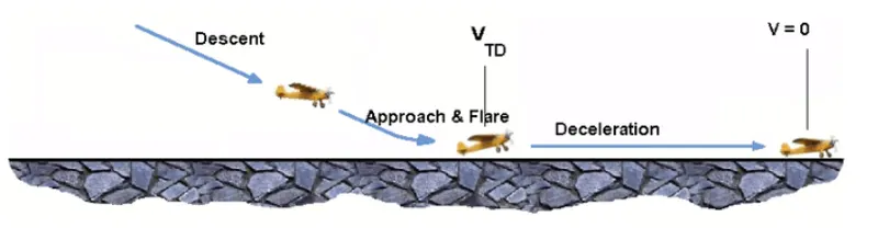 |
The touch-down velocity should be approximately the stall speed of the aircraft in the landing configuration. This will 82be achieved by a pitch maneuver during the flare portion of the approach which increases drag and decelerates the aircraft to minimum flying speed. The deceleration on the landing roll from VTD to V0 will be accomplished by braking and reverse thrust. This can be solved by the average acceleration approach that was used to estimate the take-off roll.
`(dV)/dt=(−T−D−F)/m`
The negative acceleration or deceleration value will be based on the friction coefficient for maximum braking and the value of reverse thrust.
3.6 With necessary assumptions, calculate the force and power required to push/pull an aircraft by a towing vehicle.
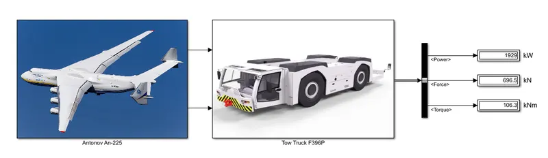
Let's consider the Antonov An-225
Co-efficient of Rolling Resistance = 0.03
Weight of the aircraft = 640000 kg
The frontal area of aircraft = 225 `m^2`
The tug that is used to pull it to the runway is SCHOPF Aircraft Tow Tractor F396P
Co-efficient of Rolling Resistance = 0.9
Weight of the tug = 54432 kg
The frontal area of tug = 10 `m^2`
Speed of both aircraft and tug while pulling it to the runway is 10 km/h, which is 2.77 m/s.
Gear Ratio for torque requirement = 0.25
The radius of the tug tire = 1638 mm
The equation to calculate forces are:
Force due to rolling resistance
`(Fr)=μ_(rr)xxmxxg`
Drag force
`(F_d)=0.5xxCd xxρxxAxxV^2`
Total force
`(F)=F_r+F_d`
The relationship between torque and force is;
`F=TxxG/r`
Simulink Model for the above calculations
 |
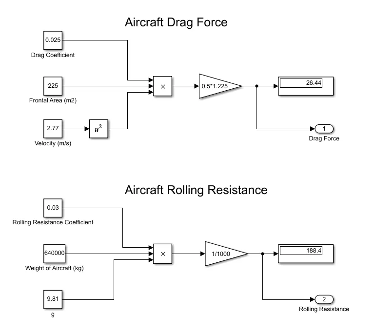 |
| FIG. Calculation of Forces acting on Aircraft |
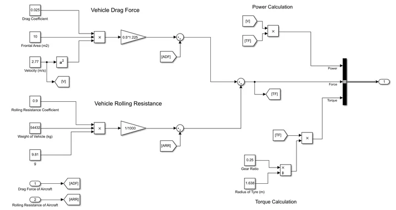 |
| FIG. Calculation of Forces acting on Towing Vehicle and Torque and Power Calculations |
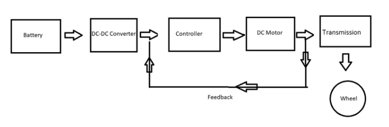
3.7 Design an electric powertrain and draw a block diagram of the powertrain.
- From the block diagram, it can be seen that the basic flow is given.
- Here a feedback path is given where the output is compared with the reference value and in order to match the reference value proper steps have been taken.
- All the necessary blocks like motor, controller, converter, and PWM are already inbuilt in a DC7 drive block.
 |
Let's take an Example
For modeling a power train let's say the motor is 80% efficient. Then the rated power is 300 kW.
The battery pack has an overall voltage of 400v.
Then I = 640000/400 = 1600 Amp
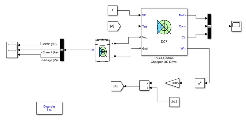
The DC drive has an internal motor, controller, converter as well as PWM.
The torque-speed relation can be given as
`T=24.7+0.0051xxomega^2`
The power train model shown below is roughly made and is only for understanding purposes.
 |
4. REFERENCES
https://www.airbusiness-gse.com/Shopf%20396C_TS.pdf
http://www.aerodynamics4students.com/aircraft-performance/take-off-and-landing.php
https://www.engineeringtoolbox.com/electrical-motor-efficiency-d_655.html