Week-7 Challenge: DC Motor Control
1. AIM
- Understand the speed control of a DC motor using BJT H-bridge from the demo model.
- Understanding and comparing The Four-Quadrant Chopper DC Drive (DC7) block with the H-bridge model.
- Make a suitable EV model using the DC7 block.
2. OBJECTIVE
- To understand the BJT H-bridge circuit and how to control the speed using it.
- To compare the DC7 block with the H-bridge model.
- To make a suitable EV model using DC7 block.
3. METHOD
3.1 Speed control of a DC motor using BJT H-bridge.
The components used in the circuits are:
 |
A Bipolar Junction Transistor (also known as a BJT or BJT Transistor) is a three-terminal semiconductor device consisting of two p-n junctions that are able to amplify or magnify a signal. It is a current controlled device. The three terminals of the BJT are the base, the collector, and the emitter. |
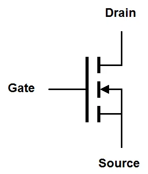 |
MOSFET stands for Metal Oxide Silicon Field Effect Transistor or Metal Oxide Semiconductor Field Effect Transistor which is a type of insulated-gate field-effect transistor that is fabricated by the controlled oxidation of a semiconductor, typically silicon. The voltage of the covered gate determines the electrical conductivity of the device; this ability to change conductivity with the amount of applied voltage can be used for amplifying or switching electronic signals. |
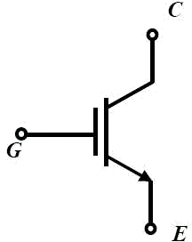 |
IGBT stands for an insulated-gate bipolar transistor. It is a bipolar transistor with an insulated gate terminal. The IGBT combines, in a single device, a control input with a MOS structure and a bipolar power transistor that acts as an output switch. IGBTs are suitable for high-voltage, high-current applications. |
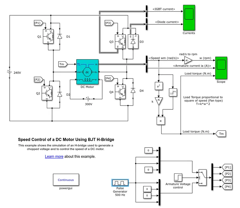 |
| FIG. Speed Control of DC Motor using BJT H-bridge |
- The above block works on the basis of an H-bridge circuit.
- The model consists of 4 BJT and 4 diodes.
 |
 |
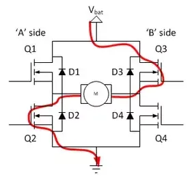 |
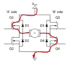
| FIG. H-bridge circuit | FIG. Q1 and Q4 Active | FIG. Q2 and Q3 Active |
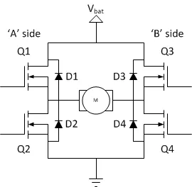
An H-bridge is an electronic circuit that switches the polarity of a voltage applied to a load. These circuits are often used in robotics and other applications to allow DC motors to run forward or backward. It is a rather simple circuit with 4 switching elements with load at the center and in H-configuration. The switching elements are generally transistors (bipolar or FET) and IGBT for high voltage application.
The H-bridge arrangement is generally used to reverse the polarity/direction of the motor, but can also be used to 'brake' the motor, where the motor comes to a sudden stop, as the motor's terminals are shorted, or to let the motor 'free run' to a stop, as the motor is effectively disconnected from the circuit.
- The BJT's are run as either Q1 & Q4 or Q2 or Q3. They are not run simultaneously because this will result in a short circuit.
- The working of the H-bridge is such that two transistors are switched simultaneously i.e Q1 & Q4 or Q2 & Q3.
- When Q1 & Q4 are operated, there is a positive voltage applied to the motor. And when they are switched OFF then the diodes D2 and D3 are freewheeling.
- When Q2 & Q3 are operated, there is a negative voltage applied to the motor. And when they are switched OFF then the diodes D1 and D4 are freewheeling.
This arrangement is used to run the DC motor in one direction for the first half cycle and in the other direction for the next half-cycle. It consists of basically 2 PNP and 2 NPN transistors connected along with diodes.
- The input is given by the user and according to the input, the power converter will turn the motor ON/OFF.
- In the model the cycle is run for 1 sec, hence the half cycle is of 0.5 secs.
- Goto and From blocks are used for providing the necessary signals at the needed place.
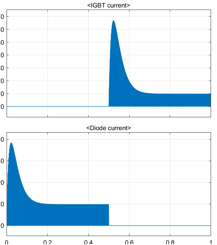
- In the plot, there is a current shoot up due to the back emf, which occurs when the polarities are changed. This shoot up is in the reverse direction and it depends on the amount of back emf.
- So to reduce the back emf, in practical use we give some kind of time delay. This time delay reduces the shoot up and the current, as well as the emf, comes to 0.
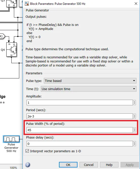
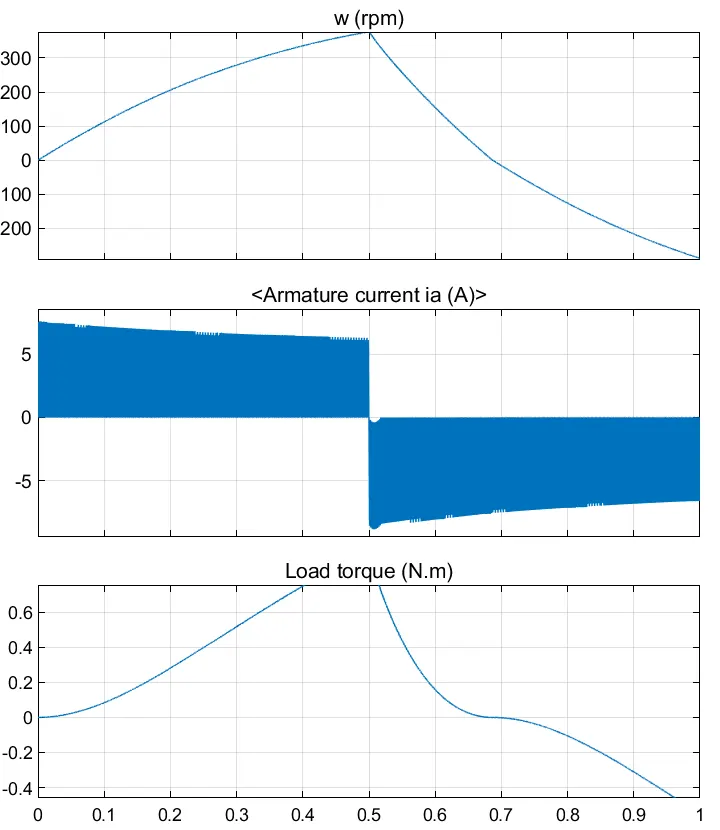
- So in the model, first we change the pulse width to 45, the shoot up is reduced but there is a small deviation.
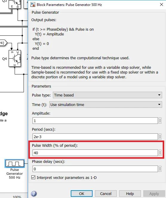
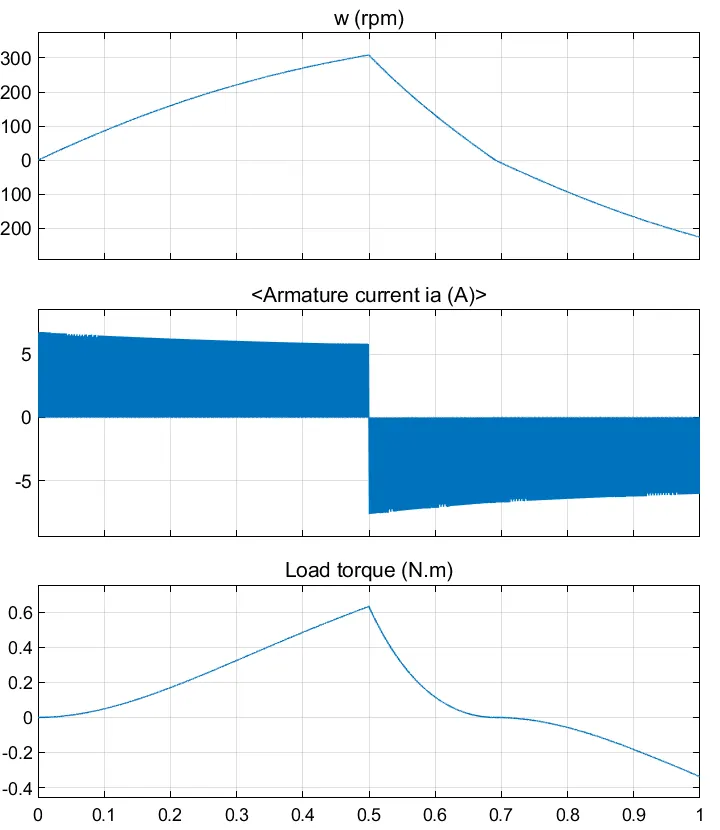
- So next we change the pulse width to 40, here we get the current value as 0 which is what is desired.
- But changing the pulse width so low, the speed and torque also reduce which is not desired practically.
- So we take these values just for study purposes.
 |
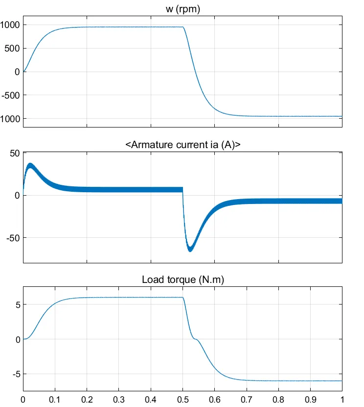 |
| FIG. Plot 1 | FIG. Plot 2 |
|
We can see that in Plot 1
In Plot 2
|
|
 |
 |
| FIG. Plot 1 | FIG. Plot 2 |
|
When we change the pulse width to 45 there is a drastic decrease in the shoot up in the current. But there is still a small shoot up which we can eliminate by further reducing the pulse width. But as we reduce the back emf current shoot up the speed and torque reduces as well. |
|
 |
 |
| FIG. Plot 1 | FIG. Plot 2 |
|
We get the desired output when we reduce the pulse width to 40. The shoot-up current is 0 but there is a drastic reduction in speed and torque as compared to when the pulse width was 75. |
|
3.2 Refer to the help section of ‘The Four-Quadrant Chopper DC Drive (DC7) block’. Compare it with the H-bridge model.
In H-bridge the Bipolar Junction Transistor (BJT) acts as IGBT when used for power switching.
The Four-Quadrant Chopper DC Drive (DC7) block represents the chopper drive for DC motors and has four quadrants and is DC supplied. Closed-loop speed control by using four quadrants is there in this block.
The chopper duty cycle corresponding to the armature current is obtained using a PI controller. The IGBT block does not simulate the gate current controlling the BJT or IGBT. The switch is controlled using the Simulink signal (1 or 0). The PI controller is absent in the H-bridge.
The BJT H-bridge operates only in two modes i.e Forward and Reverse. Hence the main advantage of the Four Quadrant chopper drive as compared to the other drives is that it operates in all four quadrants i.e.
- Forward Motoring (First Quadrant)
- Forward Braking (Second Quadrant)
- Reverse Motoring (Third Quadrant)
- Reverse Braking(Fourth Quadrant)
The Four Quadrant chopper drive uses ramps to reduce the shoot up current and provide stability. Whereas in H-bridge the current shoot-up is high due to switching losses and can be reduced by changing the pulse width.
Therefore in overall performance and stability, the Four Quadrant chopper drive is better compared to the H-bridge.
3.3 Make a suitable EV model using DC7 block and make a result report.
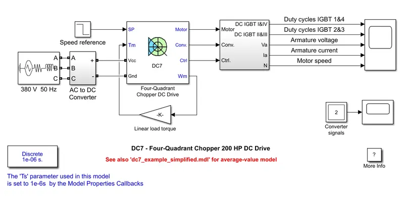 |
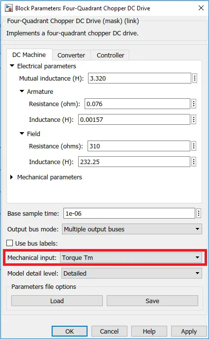 |
| FIG. Input Given as Torque |
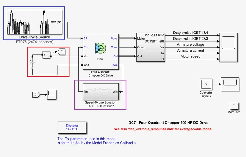 |
| FIG. Modification for EV model in DC7 block |
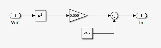 |
| FIG. Speed-Torque Equation Sub-system |
We need to make a suitable EV model so hence we need a suitable input which is Torque.
We use the Speed-Torque relation equation:
`T = 24.7 + (0.0051)xxomega^2`
We can use this equation to give the Torque input to the model and we will get the output accordingly.
We make a sub-system to formulate the equation in Simulink using the constant, gain, sum, and squaring block.
We use a drive cycle input block for the EV model.
We need a DC voltage source to simulate the battery in an EV. We give the voltage across the battery as 400 which is between the limit of 200V to 800V. This is the range of voltage that is used on EV.
Then we run the simulation and get the results.
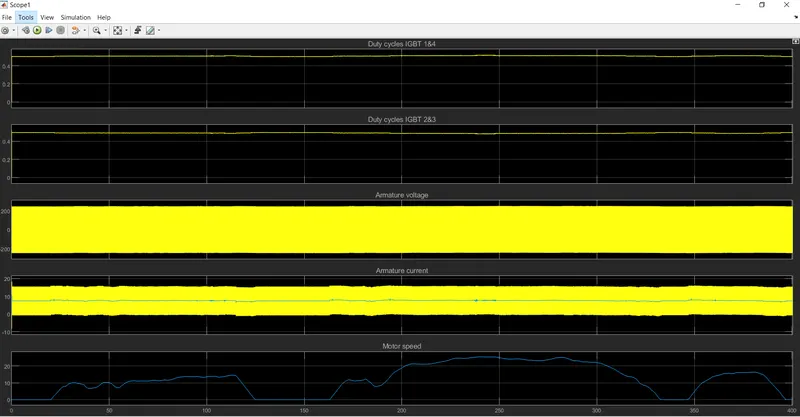 |
| FIG. The plot of DC7 block with an EV model |
- The Duty cycle plot for IGBT 1 & 4 increases during acceleration and decreases during deceleration
- The Duty cycle plot for IGBT 2 & 3 is opposite to the above plot.
- Armature voltage remains constant throughout the cycle.
- Armature current increases or decreases according to the speed.
- The last plot shows the motor speed throughout the cycle.
4. LEARNING OBJECTIVE
- To learn the working of the H-bridge circuit.
- To learn the difference between the H-bridge and DC7 circuit.
- Learned to make aN EV model using DC7 block.