Week-6 Challenge: EV Drivetrain
1. AIM
- Understand the different power converter circuits used in EV and HEV.
- Find the Steady State speed in an EV from the Torque-Speed characteristics equation.
- Understand the Induction and DC Motors.
2. OBJECTIVE
- To get a fundamental understanding of the types of power converter circuits used in EV and HEV.
- To find the speed using the torque-speed equation.
- To find the best option in motors for an EV and HEV.
3. METHOD
3.1 Which types of power converter circuits are employed in EV and HEV?
Power Electronics is the electronics applied to conversion and control of electric power.
Purpose of Power Electronics:
To process and control the flow of electrical energy by supplying voltages and currents in a form that is optimally suited for the user loads.
The control signals are generated by two methods:
- Analog
- Digital
The component used in EV and HEV is Power Convertor.
The types of Power Converters:
- AC to DC (Diode Rectifiers): It converts AC to unipolar (DC) current
- DC to AC (Inverter): It converts DC to AC of desired frequency and voltage
- DC to DC (Chopper): It converts constant to variable DC or variable DC to constant DC
- AC to AC (AC voltage regulator): It converts AC of the desired frequency and/or desired voltage magnitude from a line AC supply.
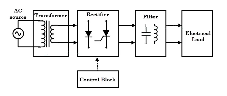 |
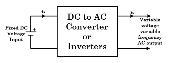 |
| FIG. AC to DC convertor | FIG. DC to AC convertor |
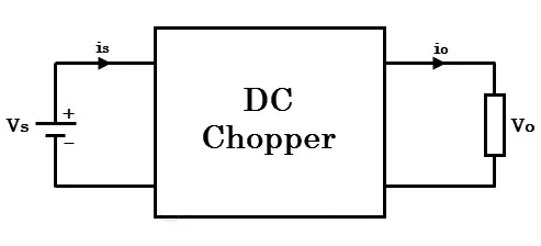 |
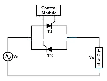 |
| FIG. DC to DC convertor | FIG. AC to AC convertor |
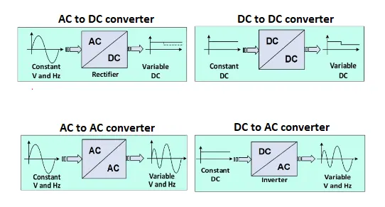 |
| FIG. Convertors with inputs and outputs |
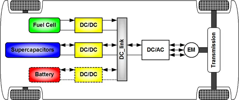 |
| FIG. DC to DC Converter used in EV |
3.2 Calculation of the Steady State speed in an EV from the Torque-Speed characteristics equation.
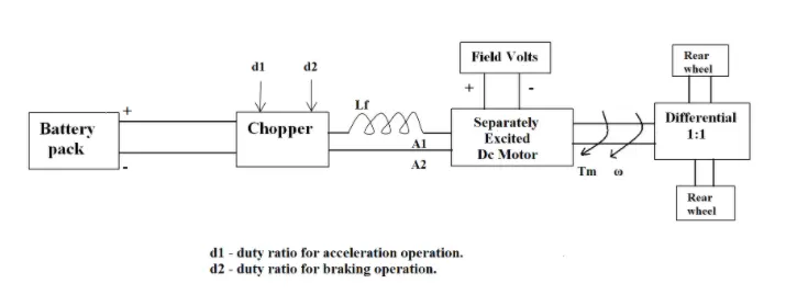 |
Motor and Controller Parameters:
Rated Armature voltage = 72 V
Rated armature current = 400 A
`Ra` = 0.5Ω
`kphi` = 0.7 Volt second
Chopper Switching frequency = 400 Hz
The vehicle speed-torque characteristics are given by the below equation
`Tv = 24.7 + (0.0051)*omega^2`
What is EV steady-state speed if the duty cycle is 70%?
Rated Armature Voltage change after including the duty cycle
V = `72xx0.7` = `50.4` V
As the Torque equation is given, we need to find speed in rad/s.
We use the other relation given below:
`T = (V*kphi)/(Ra)-(kphi^2*omega)/(Ra)`
where
`T` = Torque
`V` = Armeture Voltage
`Ra` = Armeture Resistance
`kphi` = Machine constant
`omega` = Speed (rad/s)
Comparing the two equations, we get
`24.7 + (0.0051)*omega^2` = `(V*kphi)/(Ra)-(kphi^2*omega)/(Ra)`
Substituting the above values, we get
`24.7 + (0.0051)*omega^2 = (50.4xx0.7)/0.5-(0.7^2xxomega)/0.5`
`24.7 + (0.0051)*omega^2 = 70.56 - 0.98*omega`
`(0.0051)*omega^2 +0.98*omega - 45.86 = 0`
To get the Speed we need to find the roots of the above equation,
Since it's a quadratic equation in the form `Ax^2+Bx+C = 0`
Hence to find the roots we use the equation below:
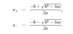 |
We get the roots as
`omega1`= 38.91 rad/s
`omega2`= -231.07 rad/s
Since the Speed value cannot be negative, we get
`omega = 38.91` rad/s
3.3 Explain in brief the author’s perspective on the topic 'Induction Versus DC brushless motors by Wally Rippel, Tesla'
The author tells us about the Induction and Dc motors. He explains the history, Construction, and Working of both the motors. As there are two sides to a coin, he explains the positives and negatives of the Induction and DC motors. He also tells us about the differences and common things between the two motors.
Brushless DC motors
- includes two or more permanent magnets to produce a DC magnetic field.
- Magnetic field enters stator and produces torque interaction between rotor and stator.
- To keep torque constant, the stator magnetic field and current are continuously varied and hence the conversion of electrical to mechanical energy is optimally efficient.
- A device that provides current control is the inverter.
Induction Motors
- 3-Phase induction motor was invented by Nikola Tesla before 1889.
- No magnets are required.
- The current flowing through the stator windings produces the rotating magnetic field which rotates the rotor.
- The current produced is proportional to the Voltage hence there is a speed difference.
- This produces the required rotor torque.
the stators for the 3-phase induction motor and the DC brushless motor are virtually identical. Both have three sets of windings that are inserted within the stator core. The difference between the two motors is the rotor.
Both DC brushless and induction drives use motors having similar stators. Both drives use 3-phase modulating inverters. The only differences are the rotors and the inverter controls. DC brushless drives require an absolute position sensor, while induction drives require only a speed sensor; these differences are relatively small.
The heat produced in the rotor is much less in DC brushless motor as compared to the Induction motor. Rotor cooling is easier and peak point efficiency is generally higher for this drive. The DC brushless drive can also operate at a unity power factor, whereas the best power factor for the induction drive is about 85%.
In an ideal brushless drive, the strength of the magnetic field produced by the permanent magnets would be adjustable. When maximum torque is required, especially at low speeds, the magnetic field strength should be maximum. This adjustment is not possible in an Induction motor.
Induction machines are more difficult to control. Achieving stability over the entire torque-speed range and over temperature is more difficult with induction than with DC brushless. This is because the speed variation depends on the frequency input which is difficult to achieve.
The DC brushless motors are Costly to make as compared to the Induction motors because of the use of Permanent magnets.
He concludes by saying that DC brushless drives will likely continue to dominate in the hybrid and coming plug-in hybrid markets, and the induction drives will likely maintain dominance over the high-performance pure electrics. Hence, he is saying that both the motors have their own advantages in the respective types of their application.
Since most of the hardware in both motors is common, he believes that in the future both the motors will be used side by side to increase the efficiency of the HEV and EV.
4. LEARNING OUTCOME
- Learned the types of power converter circuits used.
- Learned how to calculate the Steady State speed from the Torque Speed characteristics equation.
- Get to know the Induction and DC motors and try to understand which is best from the two.