Week -2
1. AIM
- Make a Simulink model of Doorbell using a solenoid block.
- Use a thermistor to sense the temperature of a heater and turn the fan on or off as per the conditions.
2. OBJECTIVE
- To create a block model of doorbell using a solenoid block and try to simulate it.
- To understand what a thermistor is and to find the threshold value at which the fan will be turned on and off at any other condition.
3. METHOD
3.1 Simulation of Doorbell using a solenoid block.
- A doorbell is a signaling device having electric and mechanical components.
- The sound is produced when the electric current passes through the circuit.
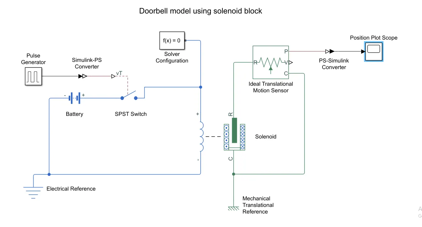
- In this simulation, we try to produce the sound in the bell using a solenoid when the switch is closed.
- The basic functioning of the bell is, when the electric current flows through the electromagnet it produces an induced current that moves the plunger and the bell rings.
- As per the given condition, we need the bell to ring for 2 secs and then stop. So for this, we use a pulse generator so that we get the required signal in continuation.
- We adjust the inputs of the pulse generator such as amplitude, time period, pulse width, and phase delay such that it produces the necessary pulse.
- A solenoid is a device comprised of a coil of wire, the housing, and a moveable plunger (armature). When an electrical current is introduced, a magnetic field forms around the coil which moves the plunger. In short, converts electrical energy into mechanical work.
- The battery is used as the current source which is required to run the simulation.
- All the circuits need to be grounded to maintain the potential difference so that the current flows.
- To check the motion of the plunger we add a Transitional motion sensor and then we change the initial position of the plunger from 0 to 5cm.
- We add scope to check the motion.
- We add a solver so that the software understands what needs to be done.
 |
 |
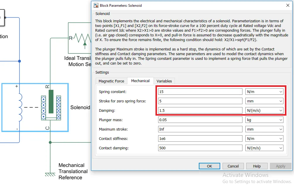 |
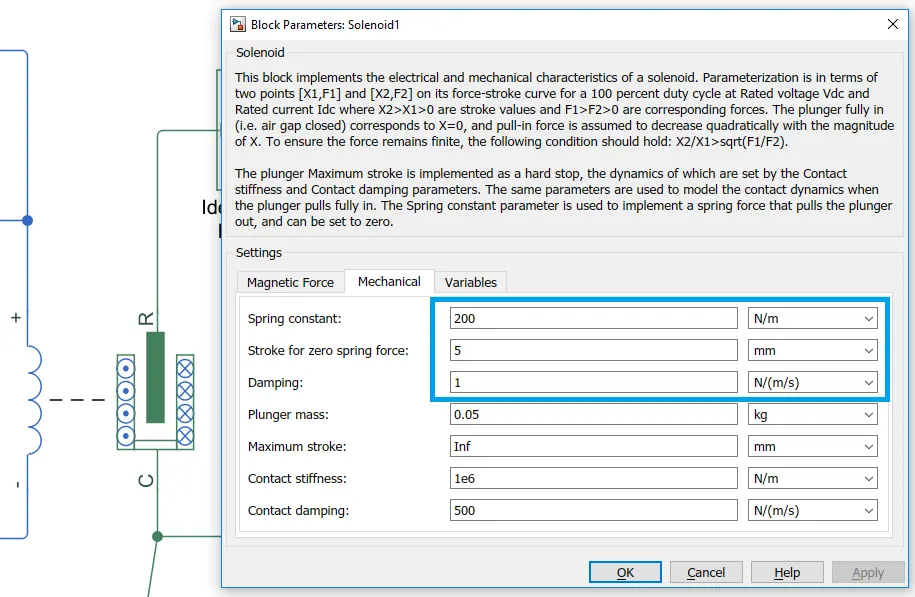
| we change the parameters of the solenoid to match our requirements. |
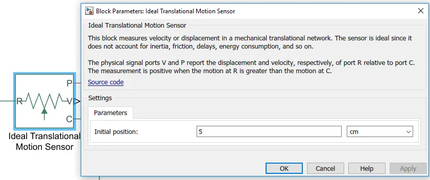 |
we change the initial position of the plunger. |
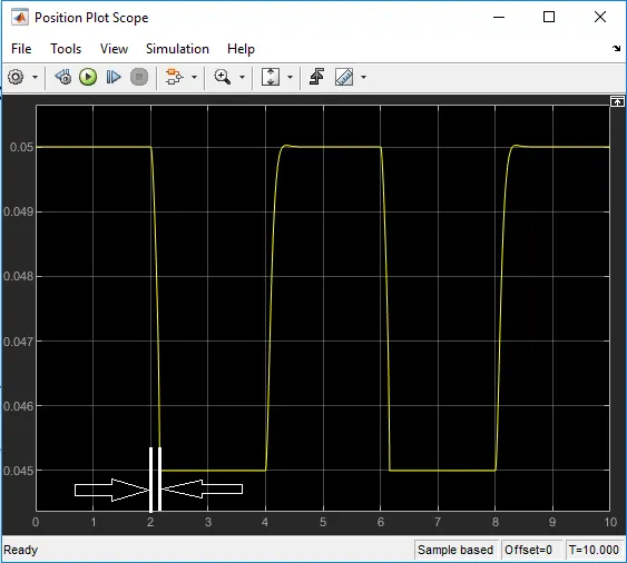 |
We see a small delay in the plot. This delay is caused when the plunger is disconnecting from the bell but is still in contact with it. |
| Fig. Change in position of the plunger |
3.2 Using a thermistor to sense the temperature in a Heater and turn the fan ON or OFF.
- A thermistor is a resistance thermometer or a resistor whose resistance is dependent on temperature.
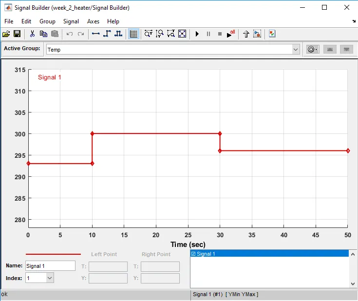
- The conditions given to us are used for the input signal. We use a signal builder for this. The three temperatures are added according to the timings which are 20°C from 0 to 10 secs, 27°C from 10 to 30 secs, 23°C from 30 to 50 secs.
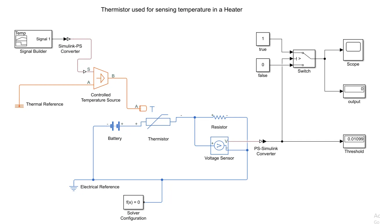
- Since the thermistor won't understand what the input is so we add a controlled temperature source.
- The output of the source is given as an input to the thermistor.
- The positive end of the source is connected to the positive of the thermistor and then the negative end of the source is grounded to create a potential difference.
- We add another resistor in series and connect a voltage sensor to it so that we can measure the value of the threshold. The sensor converts the electrical signals into a physical signal so that we can get a threshold value.
- A battery is also added so that we can run the circuit. It's also grounded to create a potential difference and we also add the solver.
- The condition to turn the fan ON is that of temperature above 25°C and for other lower values the fan must remain OFF.
- So we add a switch block that acts as an if-else loop and gives the threshold condition of the threshold voltage we got across the resistor. Where the output ON will be given at 0 and OFF will be given at 1.
- We add a display and scope to check when the fan turns ON during the 50 secs the simulation is run for.
 |
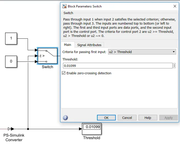 |
The threshold value which we get across the resistor which determines the ON-OFF condition for the fan is added to the switch. The threshold value obtained through the voltage sensor is 0.01099. |
 |
 |
|
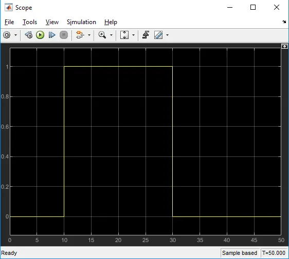
The signal builder input is given as per the conditions. The three temperatures 20°C from 0 to 10 secs, 27°C from 10 to 30 secs, 23°C from 30 to 50 secs are converted to kelvin and added in the signal. The fan will turn ON only between 10 to 30 secs. |
From the plot, we confirm that the circuit is working properly and we are getting the desired output. From 0-10 secs the fan is OFF, from 10-30 secs the fan is ON, and again from 30-50 secs the fan is OFF. |
4. LEARNING OBJECTIVE
- To understand how the solenoid works and then using that create a block model of the doorbell in Simulink.
- To simulate how the fan turns on or off for the given conditions.
- To learn the working of the thermistor and learn how it's used to control the fan according to the inputs.
5. CONCLUSION
In the first part, we simulate a doorbell using a solenoid. A solenoid is used to convert electrical energy into mechanical energy. So we create a block diagram according to it. A slight delay is observed in the plot which is a delay time the plunger takes when it moves away from the bell.
In the second part, the simulation turns the fan ON above 25 °C, so during 10 to 30 secs the fan is turned on since the temperature is 27 °C and for 0 to 10 secs and 30 to 50 secs the fan is turned OFF since the temperatures are 20 °C and 23 °C which is below 25 °C.