Week 9 - Attachment Feature Creation (Ribs & Screw Boss) - Challenge 1
AIM
Create the rib for the Drill Handle considering the design rules mentioned in the video.
THEORY
What is Draft Analysis
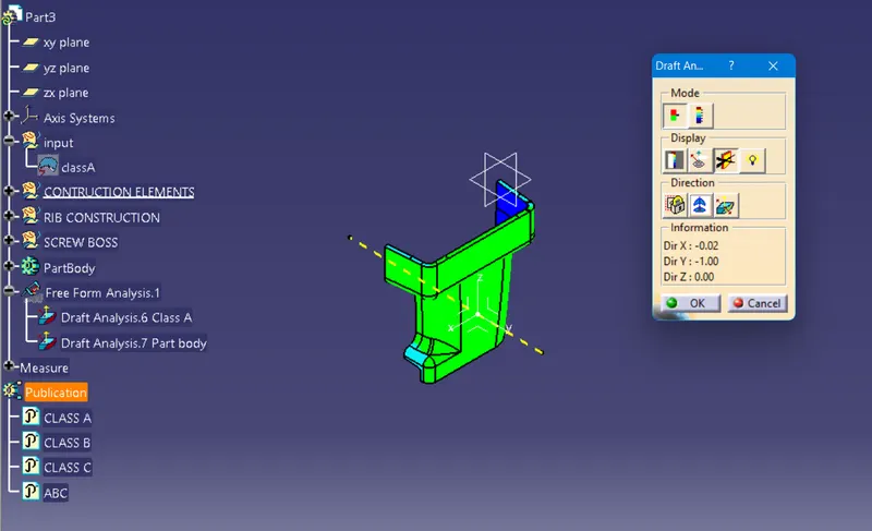
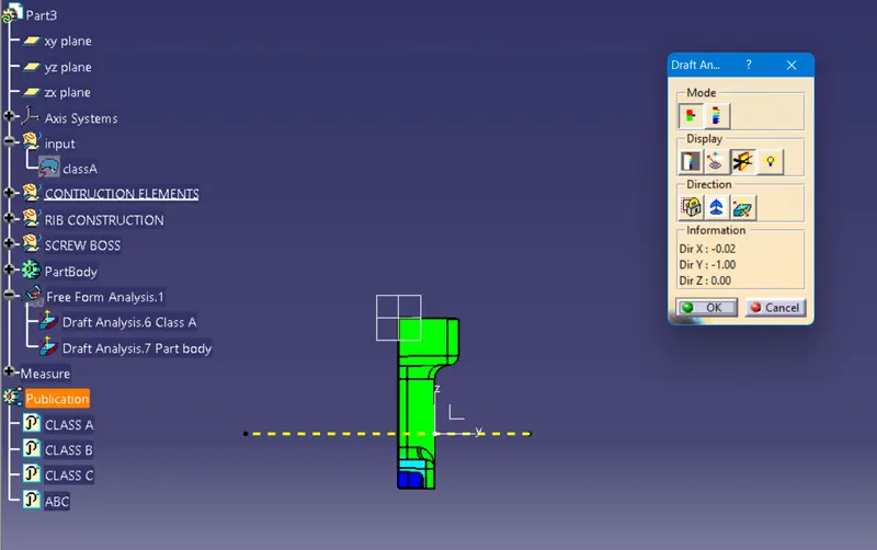
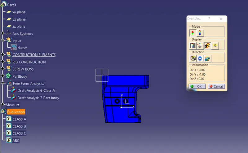
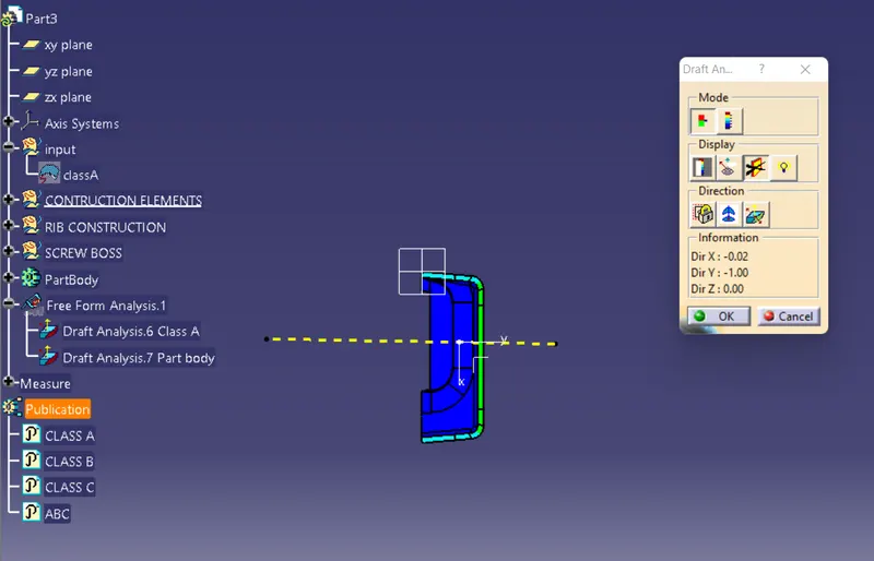
The draft analysis technique is used to analyze whether our part model created in CAD is manufacturable based on the draft condition applied. Here the part should get easily removed from the panel dies (in case of Sheet metal part) or Mold (in case of plastic).
The draft analysis command enables us to detect if the drafted part can be easily removed. This type of analysis is done based on the colour ranges identifying the zones on the analyzed element where it makes a deviation from the normal values.
Tooling Axis Creation
Tooling direction is the main consideration for the plastic part and the mold parts because it defines the movement of the mold part and the possibility of the plastic part coming out from the mold part (core & cavity). Tooling direction is critical for plastic product design because it determines mold direction
Steps Involved
- A reference point is created on the extracted surface.
- A new axis system is used to plot the extracted surface
- The x and y axis were used to develop the tooling axis using the Intersection curve
- The two clearing lines were bisected to form the Tooling axis,
- The tooling axis's graphic properties are changed to identify the Tooling axis
Ribs
Ribs are indispensable functional structures on many plastic parts. It can effectively improve the rigidity and strength of plastic parts like the H beam. By using ribs, it is not necessary to greatly increase the wall thickness of the plastic parts, and ribs are not undercut structures like the H beam whose structure will be difficult to make for plastic injection molding. So ribs work well for plastic parts that are subject to pressure, torsion, and bending. Ribs can also act as internal flow passages to aid in the plastic melt filling flow, which is of great help to the formation of complex and large plastic parts.
Ribs are generally designed on the non-appearing surface of the plastic part, and their direction is as close as possible to the flow direction of plastic melt filling. Ribs should neither be too long nor too thick, otherwise, it will increase the difficulty of injection molding, causing problems such as voids and sink marks on the back.
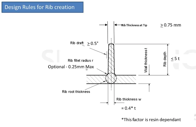
|
Generally recommended measurements for ribs in thermoplastics
|
|
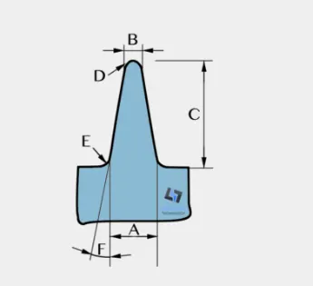 |
Generally recommended measurements for ribs in thermosetting plastics.
|
Bosses
A boss feature finds use in many part designs as a point of attachment and assembly. The most common variety consists of cylindrical projections with holes designed to receive screws, threaded inserts, or other types of fastening hardware. Under service conditions, bosses are often subjected to loadings not encountered in other sections of a component. Provide a generous radius at the base of the boss for strength and ample draft for easy part removal from the mold.
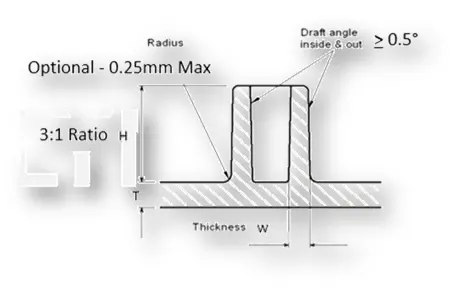
General Guidelines for Bosses:
- Draft - 0.5 degrees on the walls of boss
- Thickness - Typically 40%* of the nominal wall at the base.
- Height to Diameter Ratio - 3:1
- Radii - 0.25mm maximum radii.
FINAL