WEEK 3 SIMULINK
1. AIM
- Finding the work done by the cutting tool as it moves through a distance of 100 mm.
- Create a Simulink model to implement equation `z = 3x^2-5y+18` and store results using the To File block`
- Solve the given problems using the Mass-Spring-Damper in Simulink and Simscape model.
2. OBJECTIVE
- To find the work done by the cutting tool for the different Force values given at different instances of length.
- To make a Simulink model for solving the equation `z = 3x^2-5y+18` and using a To File to store the results.
- To give a solution to the questions asked using the Mass-Spring-Damper in Simulink and Simscape model.
3. METHOD
3.1 Finding work done by the cutting tool
- The action of the given force (F) is to move the cutting tool through a distance (d) in a straight line in the direction of the force. Now, work done (W) by the cutting too for this force is equal to the product of the magnitude of applied force and the distance through which the body moves.
- It can be calculated using the formula `W = F*d`
- We have different values of Force at different instances of distance.
- So, we can calculate the work done for this by finding the area under the curve after plotting all the values.
- We have the values
Distance (mm) 0 20 40 60 80 100
Force (kN) 60 72 65 53 44 50
- We can plot these values using the signal builder or the repeating sequence stair or a signal builder.
- The area under the curve can be calculated using the integration block.
- We can get the results in scope and display.
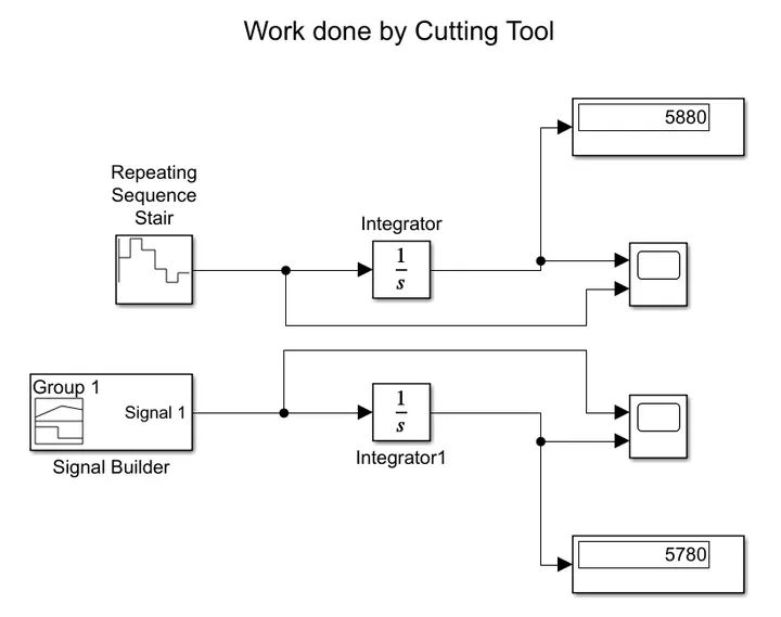 |
| fig. BLOCK DIAGRAM FOR CALCULATING WORK DONE BY CUTTING TOOL |
 |
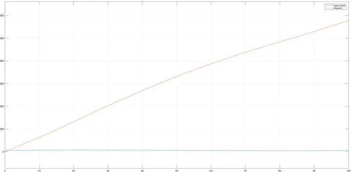 |
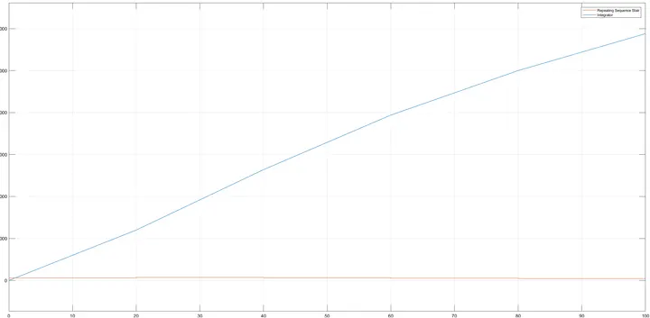
| fig. PLOT FOR REPEATING SEQUENCE STAIR | fig. PLOT FOR SIGNAL BUILDER |
- We get different values for both types of inputs.
- We can see that the signal builder plot is more refined than the repeating sequence stair.
3.2 Simulink model for the given equation `z = 3x^2-5y+18`
- We create a block diagram to find the solution for the above equation.
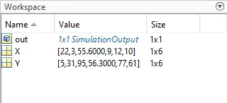
- The inputs given are x = [22 3 55.6 9 12 10] and y = [5 31 95 56.3 77 61].
- We use the basic constant blocks to add the above values, we add them from the workspace.
- The Math function block is used for squaring operation.
- Multiplication is done by using the Gain block.
- The Sum and Minus blocks are used for addition and subtraction respectively.
- We show the results in display and scope.
- We add a To File block so that we can store the results in a file.
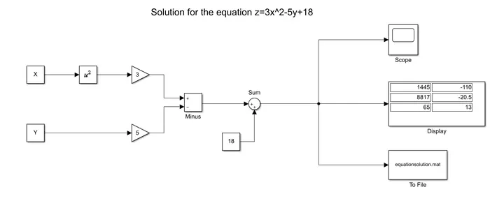 |
| fig. BLOCK DIAGRAM FOR SOLVING THE EQUATION |
 |
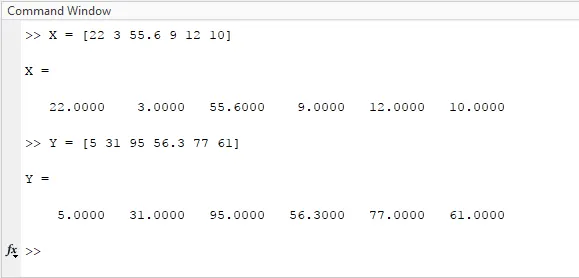 |
| fig. WORKSPACE SHOWING VARIABLES | fig. COMMAND WINDOW SHOWING INPUT VALUES |
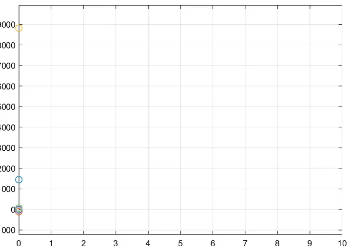 |
| fig. PLOT OF THE RESULT VALUES |
3.3 Answering the questions using the Mass-Spring-Damper in Simulink and Simscape model.
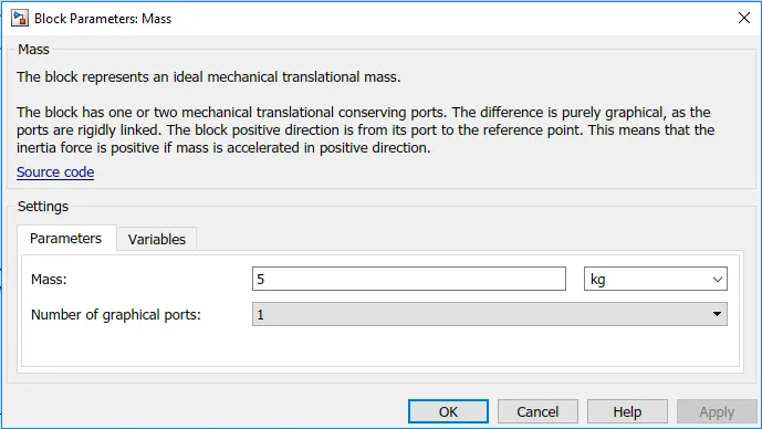
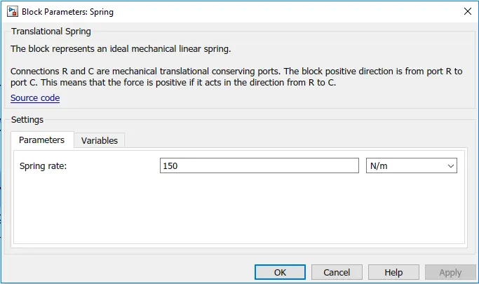
This example shows two models of a mass-spring-damper, one using Simulink input/output blocks and the other using Simscape.
The Simulink model uses signal connections, which define how data flows from one block to another. The Simscape model uses physical connections, which permit a bidirectional flow of energy between components. Physical connections make it possible to add further stages to the mass-spring-damper simply by using copy and paste. Input/output connections require rederiving and reimplementing the equations.
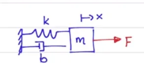
The mass-spring-damper model consists of discrete mass nodes distributed throughout an object and interconnected via a network of springs and dampers. This model is well-suited for modeling objects with complex material properties such as nonlinearity and viscoelasticity.
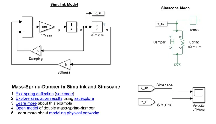 |
| fig. BLOCK DIAGRAM FOR MODEL OF MASS-SPRING-DAMPER |
3.3.1 The governing equation for the model
|
FBD in positive deflection state
|
We derive the equation using Newton's Second Law `F = m*a` `Fs = k*x` `Fd = b*dx/dt` |
|
`sum F = m d^2x//dt^2 = -Fs-Fd-F` So from the above we get `F = m d^2x//dt^2 + b dx/dt + kx` we equate the above equation to zero and we get `m d^2x//dt^2 + bdx/dt + kx = 0` For acceleration we get `d^2x//dt^2 = 1/m [-bdx/dt - kx]` This is the governing equation for the model |

 |
 |
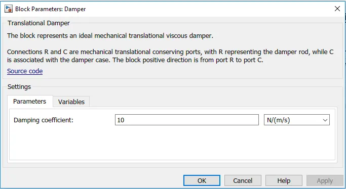 |
We change the values of the Simscape model |
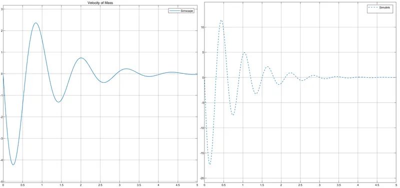 |
| fig. PLOT OF SIMSCAPE AND SIMULINK AFTER CHANGING THE VALUES |
4. LEARNING OBJECTIVE
- Learned the basic blocks and working of Simulink to make block diagrams.
- Learned how to calculate area under the curve.
- Learned how to make block diagrams to calculate a given equation.
- Learned how to use teh sample models and calculate results needed by editing the values.
5. CONCLUSION
5.1
To find the wrokdone by the cutting tool the basic formula to be used is W=F.d. Its the product of the force and the distance but since the force is changing according to the distance travelled we calculate the workdone by find the area under the curve. This is done using the integration block.
And from the results we can conclude that using the signal builder we get better results as the input is specific. And when we use the repeating sequence stair as an input the plot gives a little bit of error since the input is in form of steps and not a curve.
5.2
We can make a block diagram to solve any equation just by using the inbuilt blocks in Simulink and display the reults.
5.3
The sample models are pre designed and we can use those to simulte the results. We can determine the governing equations and also answer some questions by changing the input parameters.
The simscape model gives us a wide range of parameters that we can change to simulate the model. Whereas when we use the simulink model we have a limited range of variables that we can change.