Week - 4
1. AIM
- Implement control logic of washing machine using State Flow in Simulink.
- Make a Simulink chart for Gear shift logic as necessary.
2. OBJECTIVE
- To implement control logic of washing machine using State Flow in Simulink.
- To make a Simulink chart for Gear shift logic, indicating the position of gear as we give the input while the simulation is running.
3. METHOD
3.1 THEORY
State Flow
- State flow is a feature by which we can show the logic in form of systematic arrangement.
- The State is the operating mode of the system. For ex. car states are parking, braking, acceleration, etc.
- Inputs and conditions decide state transition.
Concept of State machine
- In an Event-driven system, the system responds to an event making a transition from one state to another.
- The Transition occurs only if the condition defining state is true.
- The MATLAB Stateflow is the graphical representation of the Finite state machine.
3.2 Control Logic of Washing Machine
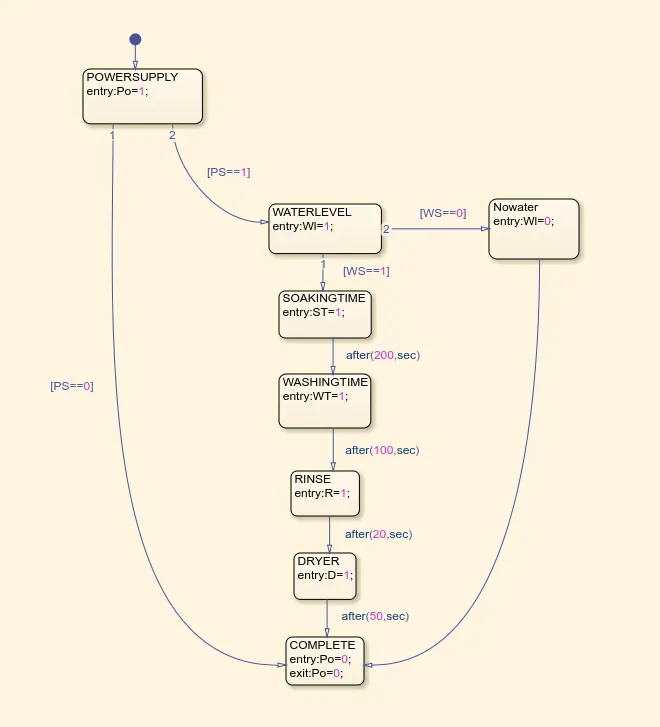
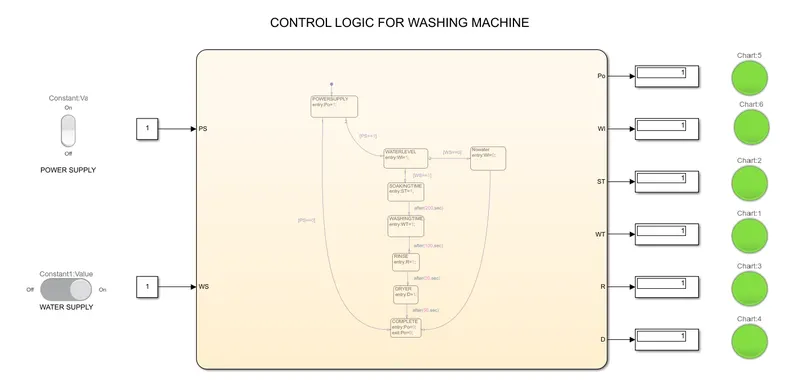
- In this control logic, we mainly focus on 2 input parameters i.e the power supply and the water supply which has to be checked.
- We use a Rocker switch to turn the power supply ON or OFF and use a Slider switch for the water supply.
- Using the switch we can toggle the input.
- The logic starts with the first POWERSUPPLY block, here we check if the power supply is ON or OFF by the condition PS==1.
- if its OFF then the process is terminated nut if it's ON then it moves to the next block.
- The next block is the WATERSUPPLY block where we check if the water is ON or OFF which is denoted by WS.
- If the water supply is ON then the process will go on but if its OFF then the cycle gets terminated.
- For the different processes, we have to give time delay which can be given by after() command and we have to specify the unit.
- Once the WS condition is true then the process goes on to the Soaking block for the time given followed by Washing, Rinse, and Drying.
- If any of the input conditions gets false then there will be no flow and it will directly come to finish.
 |
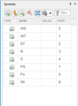 |
| Fig. CONTROL LOGIC OF WASHING MACHINE | Fig. INPUT AND OUTPUT VARIABLES |
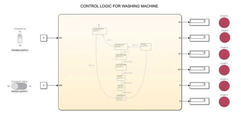 |
| Fig. CONDITION WHEN BOTH POWER SUPPLY AND WATER SUPPLY ARE OFF |
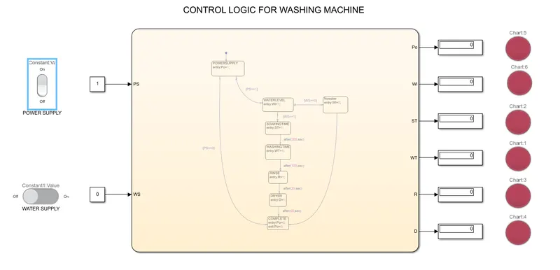 |
| Fig. CONDITION WHEN POWER SUPPLY IS ON AND WATER SUPPLY IS OFF |
 |
| Fig. CONDITION WHEN BOTH POWER SUPPLY AND WATER SUPPLY ARE ON |
3.3 Simulink chart for Gear shift logic
- In this, we have to give inputs while the simulation is running. For this, the simulation runtime is given as infinity (inf) and we have to stop the simulation manually.
- The basic working must be such that the input given must be visible on the accelerator block, then the Gear indicator must show which gear is being operated at that speed and a limit must be given.
- For each speed range, the output should be the respective gear position.
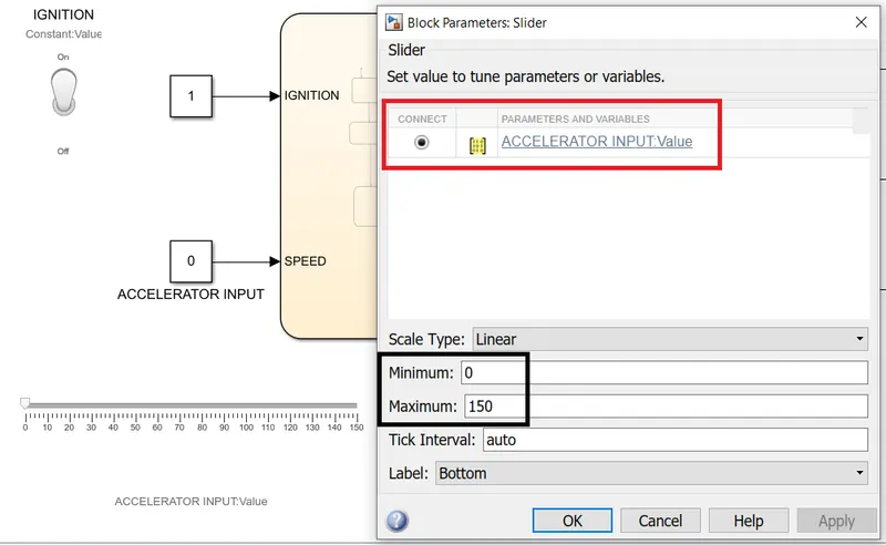
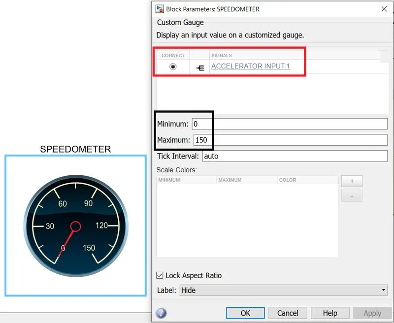
- Inputs are given with the help of a slider and the speed is shown on the circular gauge.
 |
 |
| Fig. SLIDER AS THE INPUT | Fig. SPEED SHOWN ON THE CIRCULAR GAUGE |
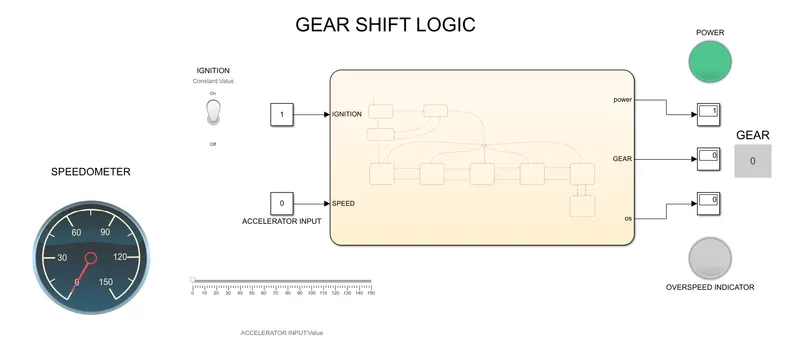
- Both the blocks are attached to the input, the slider determines the speed and the circular gauge displays the speed.
- In order to see the speed variation give proper gear position, we need to give proper conditions and connections.
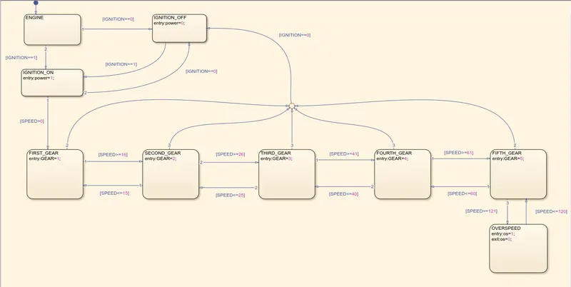
- Here the input is given as the IGNITION which determines if the engine is on or not according to the position of switch i.e position 1 or position 2.
 |
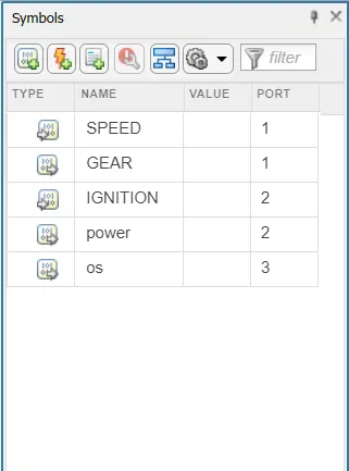 |
| Fig. CONTROL LOGIC FOR GEAR SHIFT | Fig. INPUT AND OUTPUT VARIABLES |
 |
|
| Fig. BASIC LAYOUT OF THE MODEL |
- Here we have given the input such that if the condition IGNITION==1 is true then the flow will be there and if IGNITION==0 is true then it'll terminate and indicate power off.
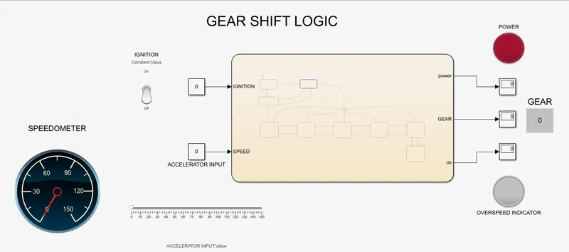 |
| Fig. SHOWING OFF CONDITION |
- Once the input conditions are matched then the speed range is detected and the corresponding Gear position is indicated.
- The speed ranges are given below.
-
Speed Range(kmph) Gear
0 to 15 1
16 to 25 2
26 to 40 3
41 to 60 4
Above 61 5
-
In order to get the above conditions and get the gear positions, the speed for gear 1 has to be greater than 0 and less than or equal to 15. The other position conditions are done similarly.
- All the input conditions are mentioned near the states represented by rectangles. The position of gear will change from 1 to 2 only if the condition is true.
- As per the conditions if the speed increases the Gear also increases and vica versa. The reverse conditions are also mentioned.
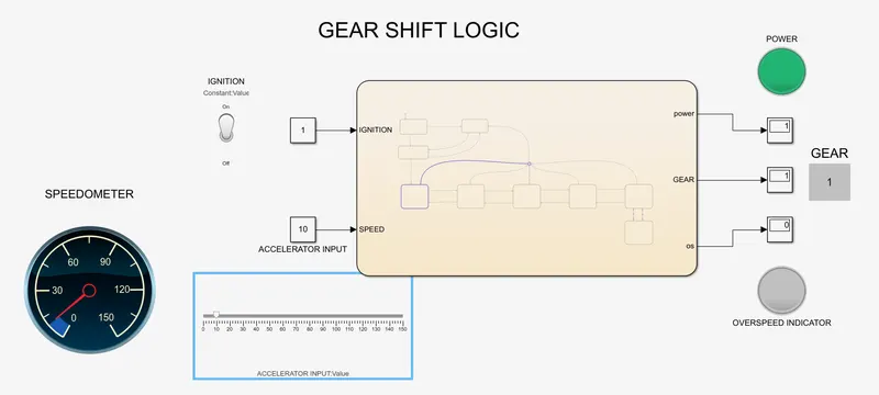 |
| Fig. SHOWING GEAR 1 |
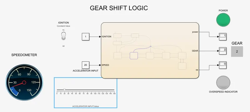 |
| Fig. SHOWING GEAR 2 |
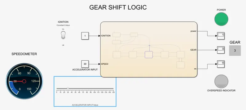 |
| Fig. SHOWING GEAR 3 |
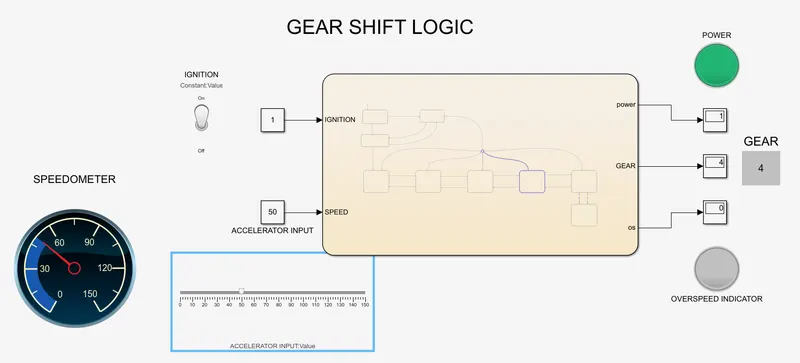 |
| Fig. SHOWING GEAR 4 |
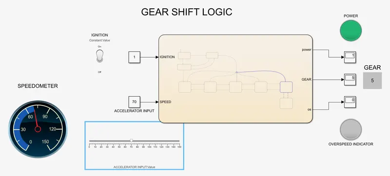 |
| Fig. SHOWING GEAR 5 |
- We have given a speed limit which gives an indication once the speed is above a certain limit. In this case, we have taken the limit as 120.
- Once the speed crosses this limit we get an indicator.
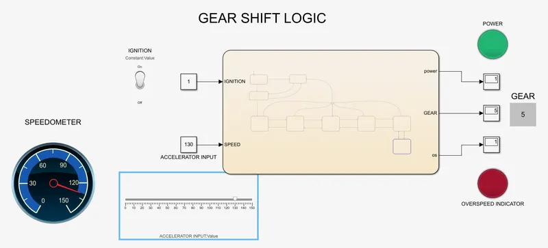 |
| Fig. OVERSPEED INDICATOR SHOWN |
- We have given a condition such that while the simulation is going on if we turn off the power then the simulation will terminate.
4. LEARNING OUTCOME
- To learn the basics of StateFlow, State, Conditions, and Simulation transitions.
- To learn how to implement the washing machine logic using StateFlow.
- To perform the Gear shifting simulation and get the outcome as the Gear positions.
- Learned the various connections that need to be made to the inputs and the state blocks.