Week 8 - Challenge 1 - Base Bracket Design
AIM
To create the Base Bracket Plastic component through the given Class-A surface. To begin with, the tooling axis for the given Class A Surface should be created meeting the requirements of the draft angle and at the end perform the Draft analysis on the model.
THEORY
What is Draft Analysis
The draft analysis technique is used to analyze whether our part model created in CAD is manufacturable based on the draft condition applied. Here the part should get easily removed from the panel dies (in case of Sheet metal part) or Mold (in case of plastic).
The draft analysis command enables us to detect if the drafted part can be easily removed. This type of analysis is done based on the colour ranges identifying the zones on the analysed element where it makes a deviation from the normal values.
What is Draft
For molded or cast parts, the draft angle is the amount of taper perpendicular to the parting line. It is measurable in degrees. Because plastic shrinks and sticks on molding surfaces as it cools, for molded or cast parts, the draft angle is the amount of taper perpendicular to the parting line. It is measurable in degrees. Because plastic shrinks and sticks on molding surfaces as it cools, we draft the walls of the plastic part so that it ejects or breaks free from the molding surfaces more easily and without dragging. To reduce the risk of damage to the parts and ensure ejection, a functional injection molding part must have drafts on both the cavity and core sides.
General guidelines to apply draft angle
- `5^o` on all vertical faces
- `1^o-2^o` works in most situations
- `3^o` minimum for a shut off
- `3^o` is required for light texture
- `5^o` or more is required for heavy texture
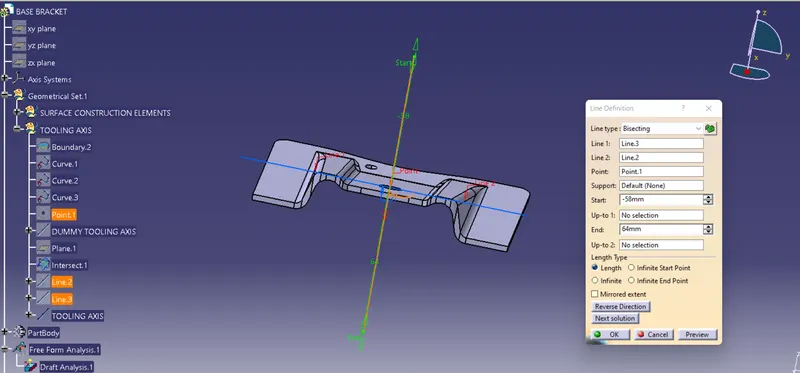
Tooling Axis Creation
Tooling direction is the main consideration for plastic part and the mold parts because it defines movement of mold part and possibility of plastic part to come-out from mold part (core & cavity). Tooling direction is critical for plastic product design because it determines mold direction
Steps Involved
- a reference point is created on the extracted surface.
- a new axis system is used to plot the extracted surface
- The x and y axis were used to develop the tooling axis using the Intersection curve
- The two clearing lines were bisected to form the Tooling axis,
- The tooling axis's graphic properties are changed to identify the Tooling axis
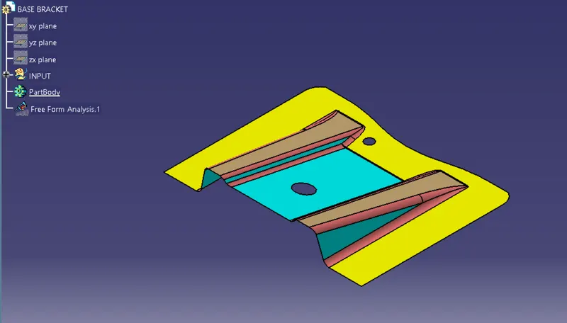
GIVEN SURFACE
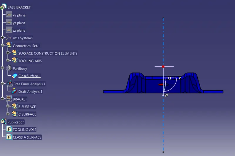
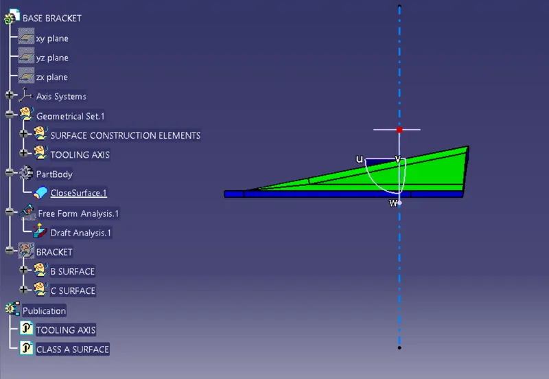
TOOLING AXIS
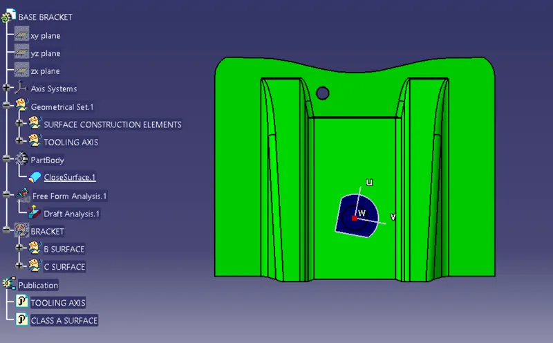
FINAL
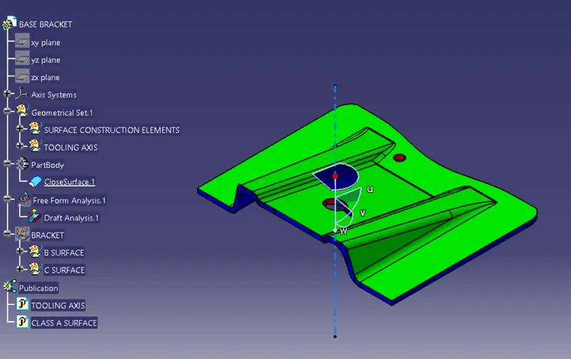
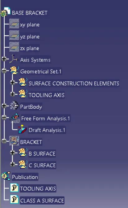
TREE STRUCTURE