Week 6 Fuel cell powered vehicle model
1. AIM
Make a MATLAB model of fuel cell powered electric vehicle and comment on results.
2. THEORY
Fuel Cell
A fuel cell is an electrochemical cell that converts the chemical energy of a fuel (often hydrogen) and an oxidizing agent (often oxygen) into electricity through a pair of redox reactions. Fuel cells are different from most batteries in requiring a continuous source of fuel and oxygen (usually from air) to sustain the chemical reaction, whereas in a battery the chemical energy usually comes from metals and their ions or oxides that are commonly already present in the battery, except in flow batteries. Fuel cells can produce electricity continuously for as long as fuel and oxygen are supplied.
There are many types of fuel cells, but they all consist of an anode, a cathode, and an electrolyte that allows ions, often positively charged hydrogen ions (protons), to move between the two sides of the fuel cell. At the anode a catalyst causes the fuel to undergo oxidation reactions that generate ions (often positively charged hydrogen ions) and electrons. The ions move from the anode to the cathode through the electrolyte. At the same time, electrons flow from the anode to the cathode through an external circuit, producing direct current electricity. At the cathode, another catalyst causes ions, electrons, and oxygen to react, forming water and possibly other products. Fuel cells are classified by the type of electrolyte they use and by the difference in startup time ranging from 1 second for proton exchange membrane fuel cells (PEM fuel cells, or PEMFC) to 10 minutes for solid oxide fuel cells (SOFC).
In addition to electricity, fuel cells produce water, heat, and depending on the fuel source, very small amounts of nitrogen dioxide and other emissions. The energy efficiency of a fuel cell is generally between 40 and 60%; however, if waste heat is captured in a cogeneration scheme, efficiencies of up to 85% can be obtained.
Fuel Cell EVs
A fuel cell vehicle (FCV) or fuel cell electric vehicle (FCEV) is an electric vehicle that uses a fuel cell, sometimes in combination with a small battery or supercapacitor, to power its on-board electric motor. Fuel cells in vehicles generate electricity generally using oxygen from the air and compressed hydrogen. Most fuel cell vehicles are classified as zero-emissions vehicles that emit only water and heat. As compared with internal combustion vehicles, hydrogen vehicles centralize pollutants at the site of the hydrogen production, where hydrogen is typically derived from reformed natural gas. Transporting and storing hydrogen may also create pollutants.
Fuel cells have been used in various kinds of vehicles including forklifts, especially in indoor applications where their clean emissions are important to air quality, and in space applications. The first commercially produced hydrogen fuel cell automobile, the Hyundai Tucson FCEV, was introduced in 2013, Toyota Mirai followed in 2015 and then Honda entered the market. Fuel cells are being developed and tested in trucks, buses, boats, motorcycles, and bicycles, among other kinds of vehicles.
MATLAB model
 |
Description
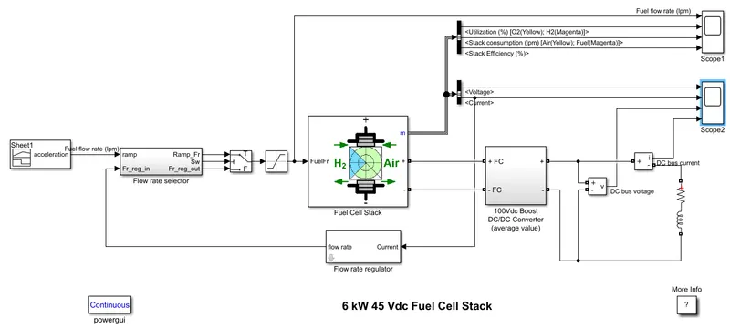
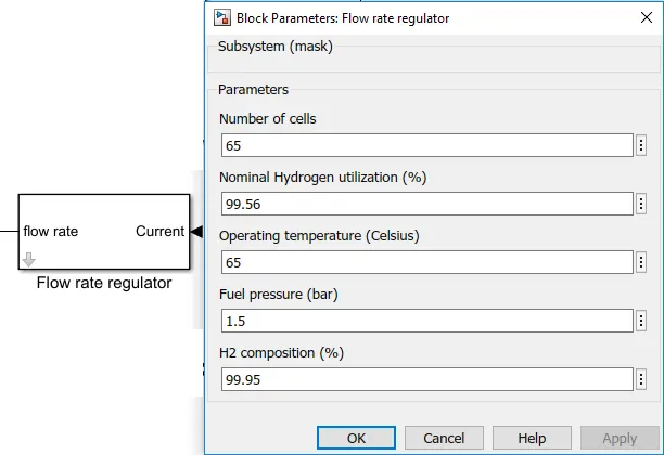
The nominal Fuel Cell Stack voltage is 45Vdc and the nominal power is 6kW. The converter is loaded by an RL element of 6kW with a time constant of 1 sec. During the first 10 secs, the utilization of the hydrogen is constant to the nominal value (Uf_H2 = 99.56%) using a fuel flow rate regulator. After 10 secs, the flow rate regulator is bypassed and the rate of fuel is increased to the maximum value of 85 lpm in order to observe the variation in the stack voltage. That will affect the stack efficiency, the fuel consumption and air consumption.
1. Load Reference
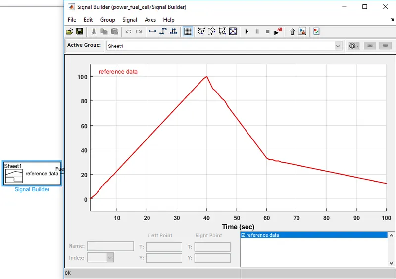 |
The Signal builder gives the loaf reference data through which the flow rate is selected. We import custom drive cycle data. |
2. Saturation block
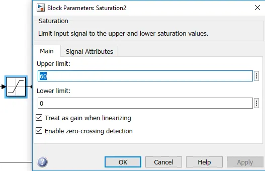 |
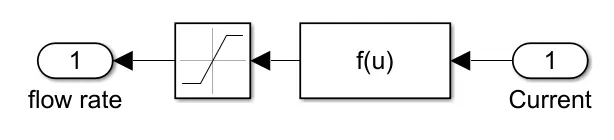
The Saturation block produces an output signal that is the value of the input signal bounded to the upper and lower saturation values. The upper and lower limits are specified by the parameters Upper limit and Lower limit. The default value given in the block is 85 which is the upper limit value for the ramp signal. The maximum speed value attained during the drive cycle can be given as the upper limit value here. Here we take 60 as the max value which is corresponding to the max speed of the vehicle. |
3. Fuel Cell Stack
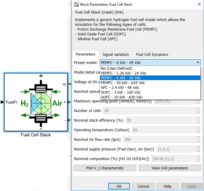 |
Implements a generic hydrogen fuel cell model that allows the simulation for the following types of cells:
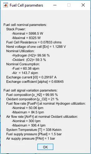
Here we take the PEMFC - 6kW - Vdc fuel cell |
 |
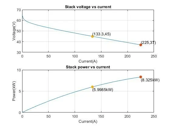 |
| FIG. CELL PARAMETERS | FIG. CELL V_I CHARACTERISTICS |
4. Flow rate Regulator
 |
 |
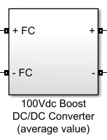
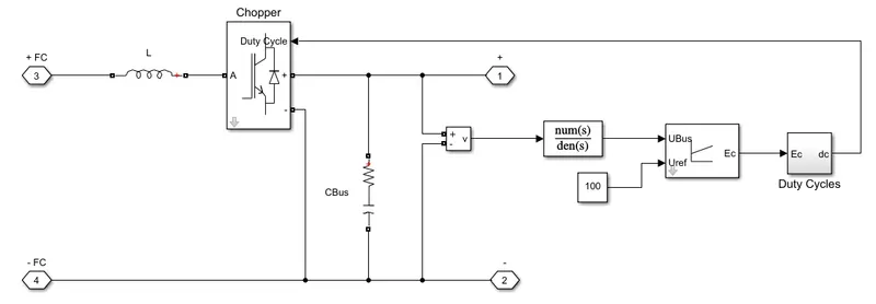
5. Boost DC-DC Converter
 |
 |
3. OUTPUT
For Simulation
- At t = 0 s, the DC/DC converter applies 100Vdc to the RL load (the initial current of the load is 0A).
- The fuel utilization is set to the nominal value of 99.56%. The current increases to the value of 133A.
- The flow rate is automatically set in order to maintain the nominal fuel utilization.
- The simulation time is set to 100s.
Scope 1 shows
- Fuel flow rate (lpm)
- Utilization of `O_2` & `H_2` (%)
- Stack Consumption (lpm)
- Stack Efficiency (%)
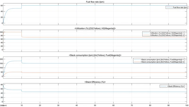 |
- The fuel flow rate rises steadily at the starting 3-4 seconds then becomes constant till 10 seconds and then it again increases sharply at the 10th second and then again becomes constant according to the drive cycle.
- The utilization of Oxygen is constant throughout and that of Hydrogen is 100% in the beginning and then falls to 80% after 10 seconds and becomes constant.
- The utilization of hydrogen increases during acceleration and decreases during deceleration.
- The stack consumption of air also increases steadily till 10 seconds after which there is a sharp change in the consumption as the necessary speed is reached and then it becomes constant.
- Similarly, that of fuel consumption is almost constant throughout.
- The stack efficiency is 80% at the start and it decreases according to the consumption.
Scope 2 shows
- Voltage
- Current
- DC Bus voltage
- DC Bus current
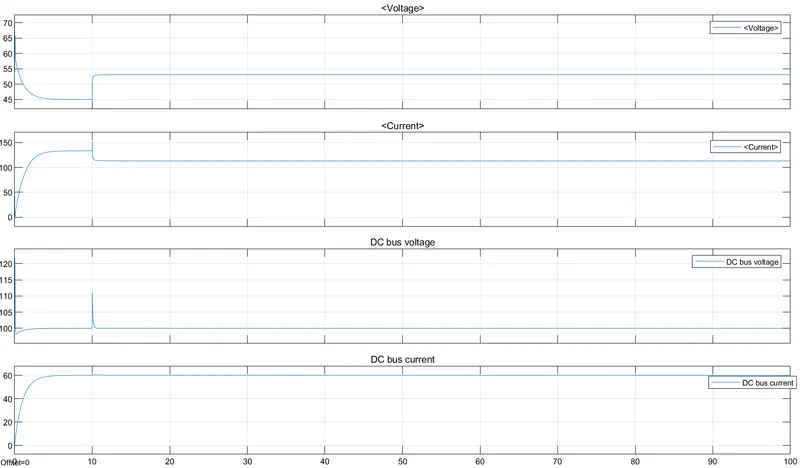 |
- Due to the RL load the voltage decreases exponentially for 10 seconds since there is acceleration then there is a sharp rise when the required condition of max speed since the is met and then it becomes constant.
- Similarly there is exponential rise in the current and then it becomes constant once the max speed is reached.
- DC voltage and current are kept almost constant to avoid the fluctuations due to load.
- The dc bus voltage is also giving a constant 100 v as it is preset to do so, there is a spike at the beginning and at 10 secs, this always during a significant deviation in vehicle acceleration.
4. LEARNING OUTCOME
We learn how the fuel cell vehicle works and also about the outputs of the parameters that affect the performance of the vehicle.