Week 8-Challenge
OBJECTIVE:
- To create 3D Meshing(Tetra mesh) for the housing model with Elements sizes: Min- 2mm, Target- 5mm, Max- 7mm, and Tet collapse: 0.15
- To create 3D tetra mesh for the two given models with 6mm element size.
SOFTWARE USED: Hypermesh
DEFINITION:
TETRA MESHING:
Tetrahedral is a four noded solid element that can be generated through the tria element by creating a volume and also through the existing volume of the geometry. These elements are used where the geometry has high thickness and complexity. The below-attached image is the representation of a tetra element. Tetra element will have 4 triangular faces with four nodes joining them together
TET COLLAPSE:
Tet collapse is one of the quality parameters, which will be checked while generating tetrahedral elements. It can be calculated by measuring the distance of a node from the opposite face, then each of the four values will be divided by the square root of the opposite face area. The minimum of four resulting values is then normalized by dividing it by 1.24.
Generally, tet collapse can be calculated by the formula = Min of(h√A)/1.24
In that formula h-represents the Height between the Node (NI) and the opposite face of the triangle
A- represents the Area of Opposite Face(area of the triangle)
METHODS TO GENERATE TETRA MESHING:
There are three methods to generate tetra meshing as stated below,
- Conversion of 2D tria to tetrahedral elements, by using tetra mesh panel.
- Using the quick tetra mesh, from the utility panel.
- Using the volume tetra mesh panel.
PROCEDURE:
HOUSING MODEL:
- First, we want to import the model by selecting file>open>model>select that housing model and click open to obtain the model in the graphical area. The selection process is shown below,
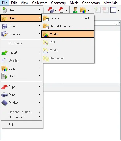
Fig: Import option
- The housing model will be shown in the graphical area after importing the file and the model are given below,
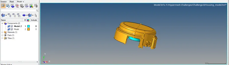
Fig: Open model
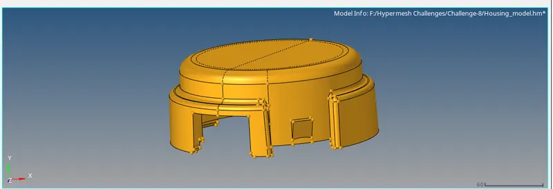
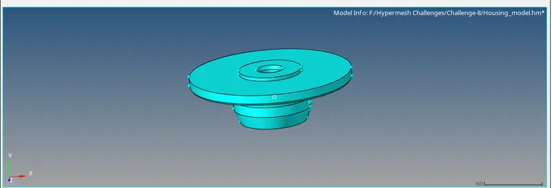
Fig: Open model
- After importing the model we want to mesh 3D tetra meshing in that model by using the different methods here we are using the quick tetra mesh, from the utility panel. To create the quick tetra mesh by selecting view>Browser>hypermesh>utility option the selection process is stated below,
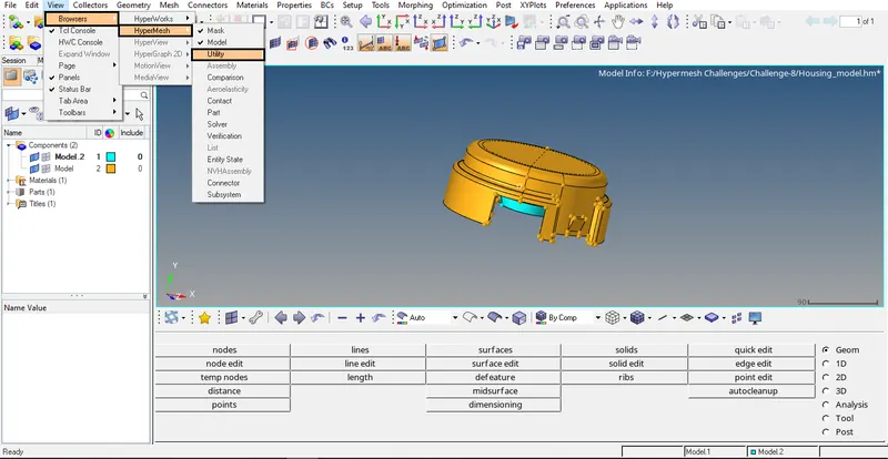
Fig: Utility option
- In the utility, tab click Geom/mesh to open the mesh tools options in that mesh tools features select the quick tetra mesh option. The selection process is shown below,
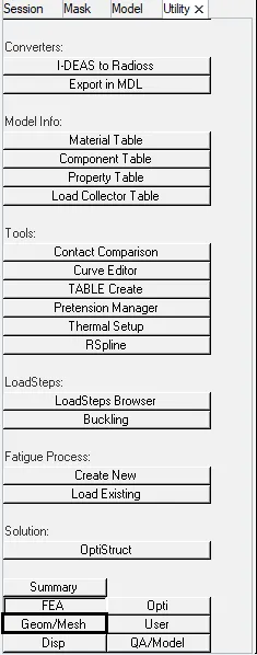
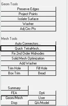
Fig: Quicktetra option
- After the quick tetra tab has opened enter the mesh size value as 5mm in that tab and also mention the minimum element size as 2mm. Now change the mesh type as trias only and enable perform mesh cleanup only check box to perform the geometry clean in that component. The quick tetra tab is shown as below,
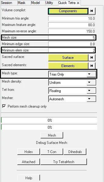
Fig: Quicktetra option
- In volume complist select the components that you want to obtain 3D tetra mesh and click proceed to perform an action of the meshing process.
- Select mesh option with perform mesh clean up only check box after giving all the values. The geometry clean up will complete and shown in that graphical area after that unselect the perform mesh clean up only check box and again click the mesh option. The selected component and the process is shown below,
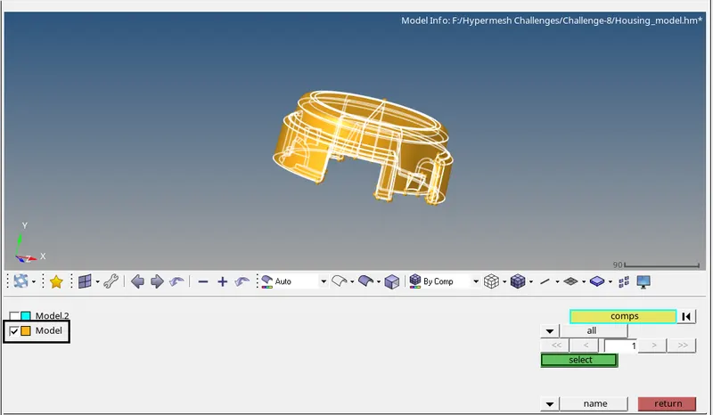
Fig: Selected component
- Now the tetra mesh is obtained in that component and they are shown below,
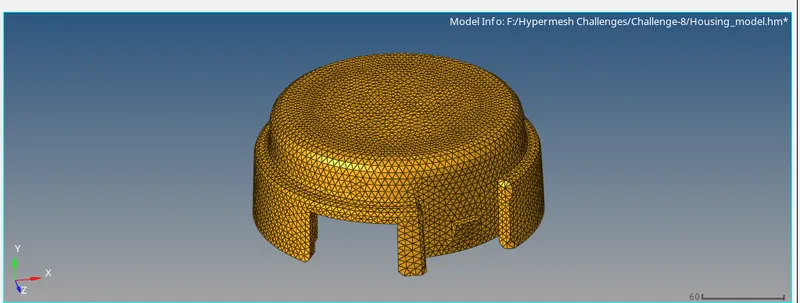
Fig: 3D Tetra mesh
- The same process has to be followed for the other component in the housing model whereas the component is selected and proceed for the meshing process through utility method. A component-2 is selected and they are shown as below,
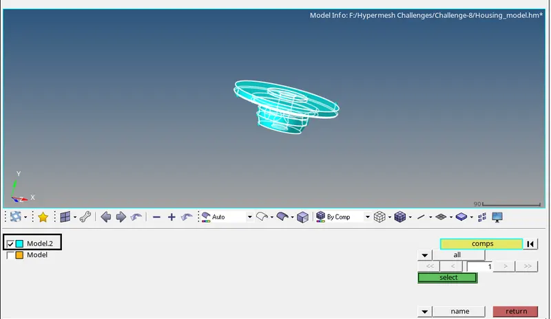
Fig: Selected component
- Now the tetra mesh is obtained in that component-2 and they are shown below,
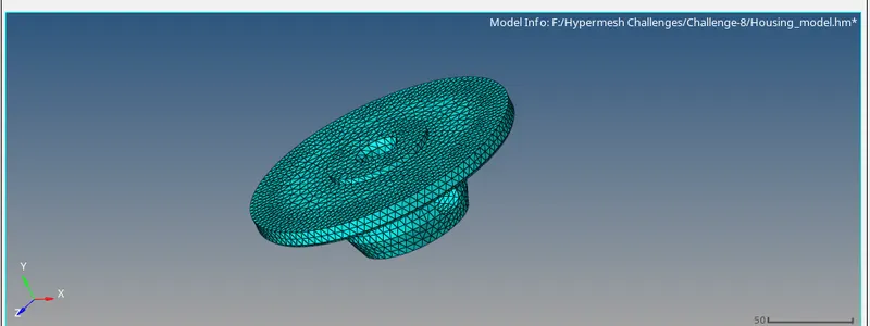
Fig: 3D Tetra mesh
- After obtaining the 3D tetra mesh we want to delete 2D mesh in that model so select delete option or press F2 to open the delete option and select the element >by config>tria3 then select the entities then click delete entity to delete the 2D mesh in that component.

Fig: Delete option
- The 2D mesh deletion for the two models and the selection process is shown below,
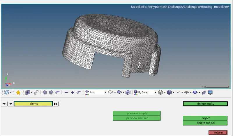
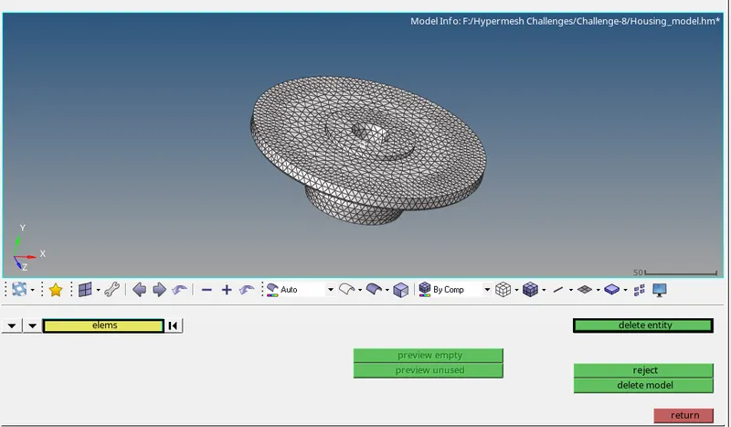
Fig: 2D element deleted
- Now the 3D tetra mesh is generated therefore check the tet collapse for that model by selecting tools>check elements>3D or click F10 key to open check elements tab and mention the tet collapse value as 0.15 that is given by an instructor.
- In this housing model, there is no tet collapse is found, and thus it shows 0% element failure for tet collapse in this model they are shown as below,
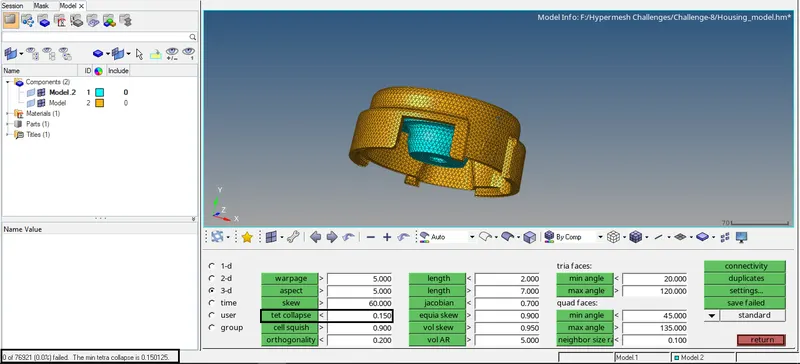
Fig: Tet collapse cleared
MODEL-2
- We want to import the model by selecting file>open>model>select that TETMESH_PM.hm file and click open to obtain the model in the graphical area. The selection process is shown below,
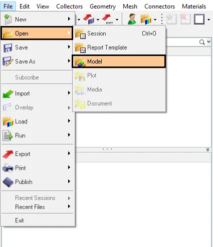
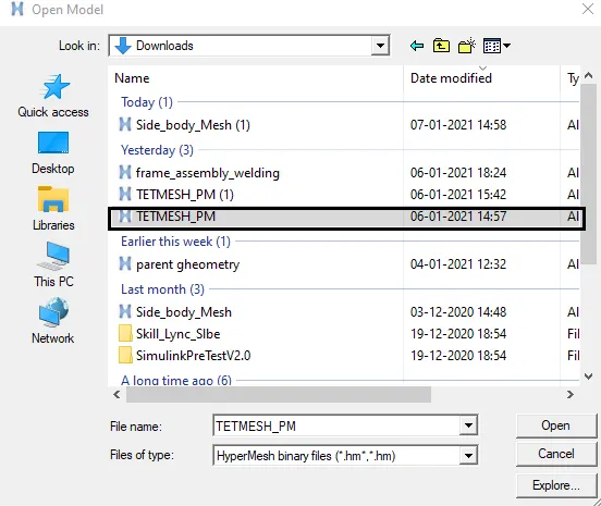
Fig: Import option
- Now the model will be shown in the graphical area after importing the file and the model are given below,
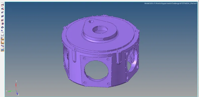
Fig: Open model
- In this model we are using the first method, conversion of 2D tria to tetrahedral elements, by using tetra mesh panel. First, we want to generate the 2D mesh in that model and then execute the 3D mesh over that mesh. Now select 2Dmesh>auto mesh or click F12 key to enter auto mesh option then select surfs and give the element size as 6mm, then change mesh type as trias and select mesh option to generate 2D mesh in that component.
- The selection process is stated as below,
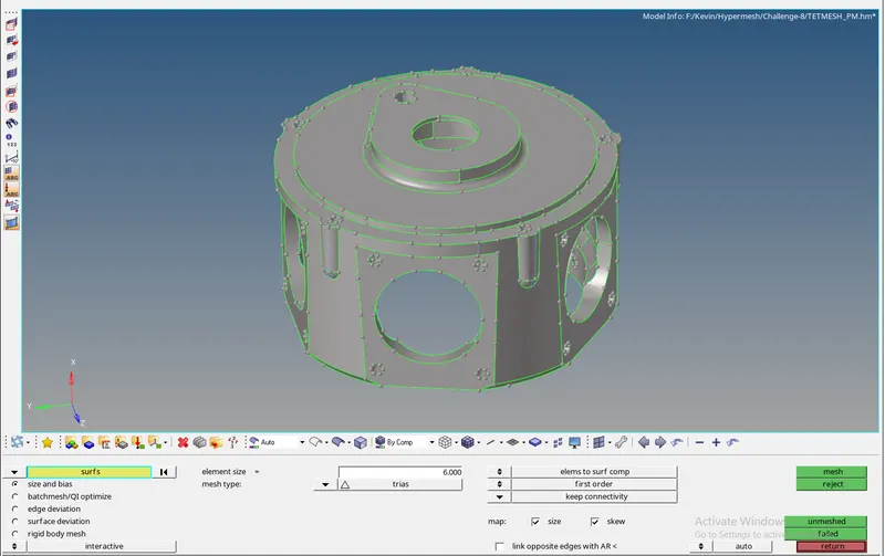
Fig: 2D mesh
- The 2D mesh is obtained and they are shown below,
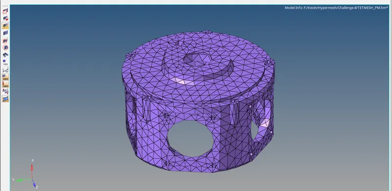
Fig: 2D meshed component
- Hence to generate the 3D mesh on the model by selecting 3D>tetra mesh>select elements and click the mesh option to obtain the 3D mesh in that model. The tetra mesh toolbar and selection is shown below,

Fig: Tetra mesh option
- The 3D tetra mesh is obtained and they are shown below,
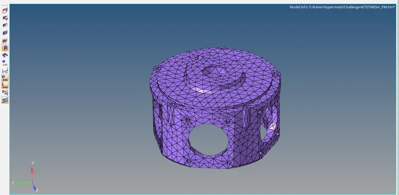
Fig: Tetra meshed component
- After obtaining the 3D tetra mesh we want to delete 2D mesh in that model so select delete option or press F2 to open the delete option and select the element >by config>tria3 then select the entities then click delete entity to delete the 2D mesh in that component. They are shown below,
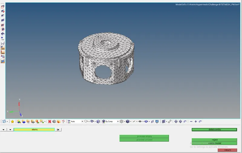
Fig: Deleted 2D elements
- In this model there will be tet collapse is occurred while checking in check elements and they could be rectified by remeshing option in 3D>tetramesh>Tetramesh parameters and enter the value of max tetra size, tet collapse value as 0.15 then select tetra remesh option and select the elements then execute mesh option.
- Therefore the remesh action is performed and the selection process is shown below,

Fig: Tetra remesh
- Hence after performed the remesh option the collapse is cleared, now there is no tet collapse is found, and thus it shows 0% element failure for tet collapse in this model they are shown as below,
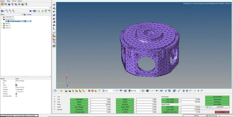
Fig: Tet collapse cleared
MODEL-3
- To import the IGES file by using importing option and select the file type as IGES and select the file and click the import option the selection process is shown below,
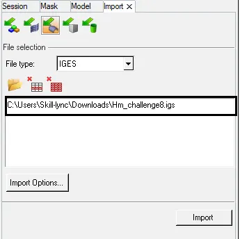
Fig: Import option
- The model will be shown in the graphical area after importing the file and they are shown below,
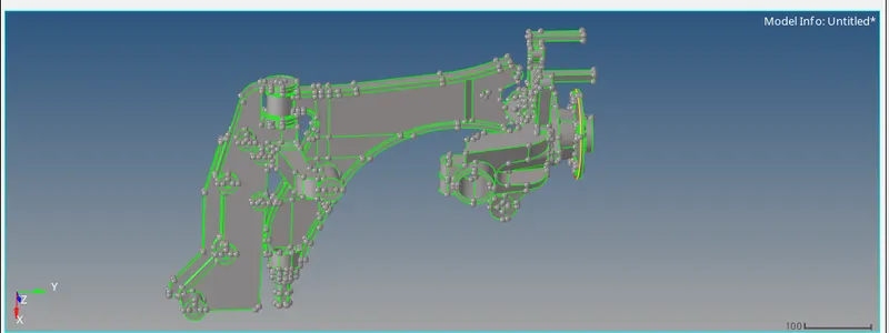
Fig: Open model
- There are different components present in that model they are listed below,
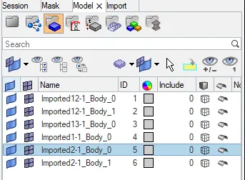
Fig: Components
- In this model before performing mesh we need to clean geometry manually for a certain component, therefore the geometry clean up is done manually and they are shown as below,
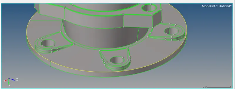
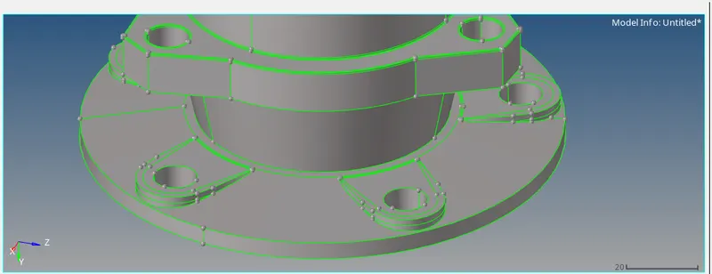
Fig: Geometry cleanup
- The gear is removed manually for the purpose of performing meshing operation they are stated below,
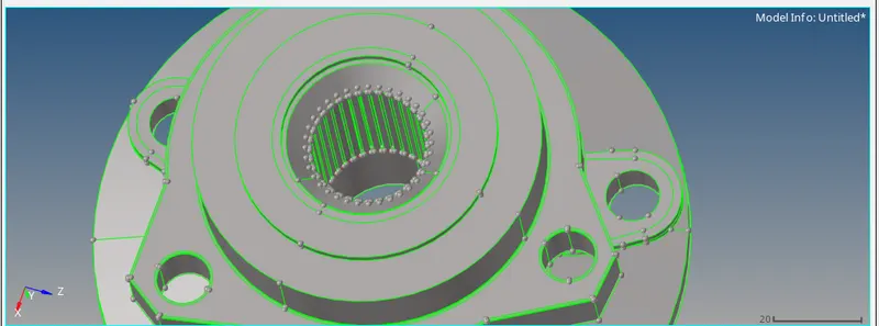
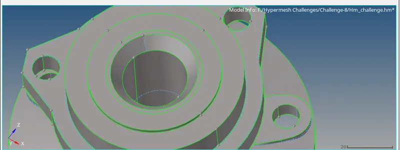
Fig: Geometry cleanup
- In the utility, tab click Geom/mesh to open the mesh tools options in that mesh tools features select the quick tetra mesh option. The selection process is shown below,
Fig: Quicktetra option
- After the quick tetra tab has opened enter the mesh size value as 6mm in that tab and also mention the minimum element size as 2mm. Now change the mesh type as trias only and enable perform mesh cleanup only check box to perform the geometry clean in that component. The quick tetra tab is shown as below,
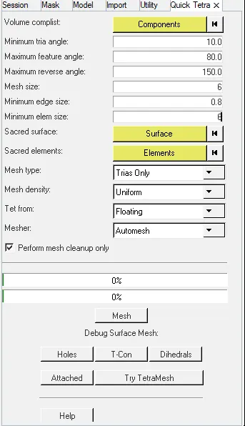
Fig: Quicktetra option
- In volume complist select the components that you want to obtain 3D tetra mesh and click proceed to perform an action of the meshing process.
- Select mesh option with perform mesh clean up only check box after giving all the values. The geometry clean up will complete and shown in that graphical area after that unselect the perform mesh clean up only check box and again click the mesh option. The selected component and the process is shown below,
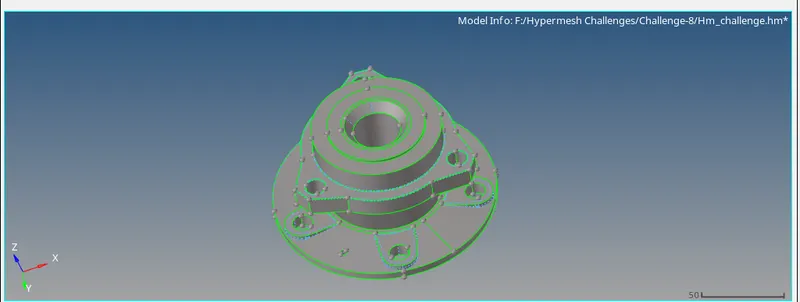
Fig: Geometry cleanup
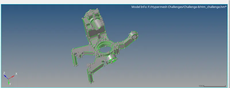
Fig: Geometry cleanup
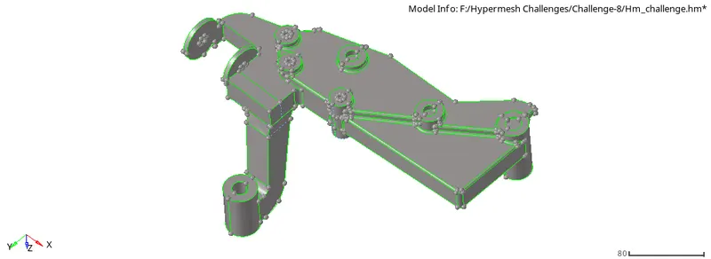
Fig: Geometry cleanup
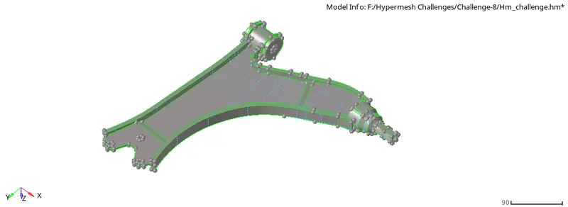
Fig: Geometry cleanup
- Now the tetra mesh is obtained in that component and they are shown below,

Fig: 3D Tetra mesh
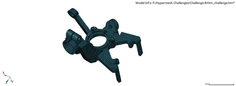
Fig: 3D Tetra mesh
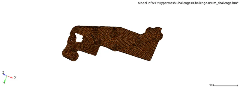
Fig: 3D Tetra mesh
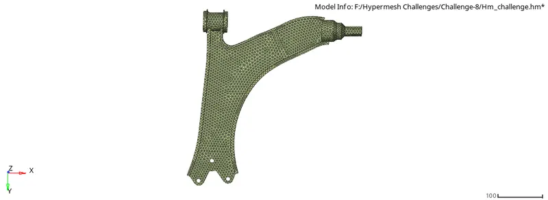
Fig: 3D Tetra mesh
- After obtaining the 3D tetra mesh we want to delete 2D mesh in that model so select delete option or press F2 to open the delete option and select the element >by config>tria3 then select the entities then click delete entity to delete the 2D mesh in that component.
Fig: Delete option
- The 2D mesh deletion for the two models and the selection process is shown below,
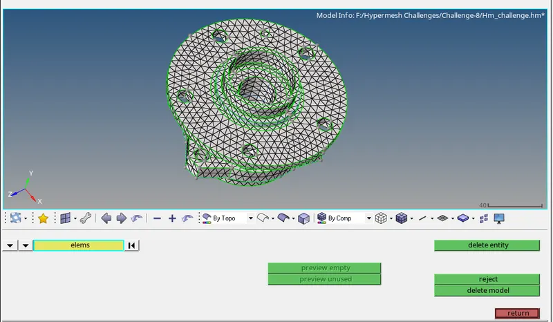
Fig: 2D element deleted
- Now the 3D tetra mesh is generated therefore check the tet collapse for that model by selecting tools>check elements>3D or click F10 key to open check elements tab and mention the tet collapse value as 0.15 that is given by an instructor.
- Here there are 88 elements(0.3%) is failed for tet collapse they are shown as below,

Fig: Tet collapse
- To rectify the failure element mask that element separately by using the mask option by pressing F5 key and select retrieve option then mask the total elements and click unmask option to separate the failure element they are shown as below,
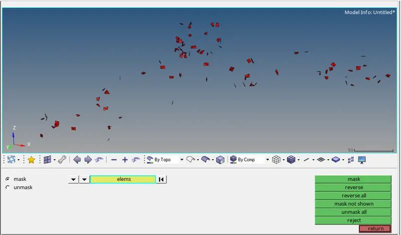
Fig: Mask option
- The tet collapse will retain by changing the distance of the two nodes by selecting the nodes and give the distance value as 5mm to clear the tet collapse failure selection process is shown below,
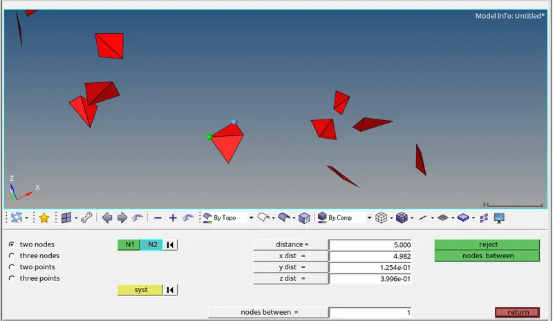
Fig: Distance option
- Hence the element is getting cleared by tet collapse failure by giving the distance value of that 3D tetra element by changing the distance of two nodes, same process is followed for other elements to clear the tet collapse.
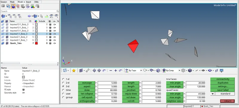
Fig: Tet collapse cleared
Therefore all the failure elements are rectified and thus it shows 0% element failure for tet collapse in this model they are shown as below,
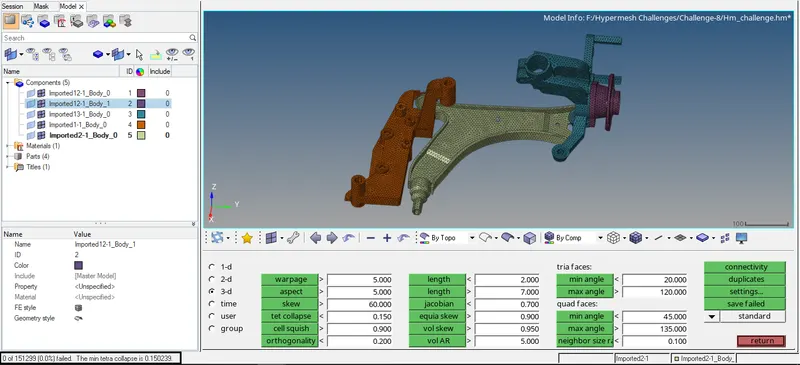
Fig: Tet collapse cleared
CONCLUSION:
Hence 3D tetra mesh for all the three models is generated and tet collapse also cleared for all the models.