Week 4- Challenge
AIM:
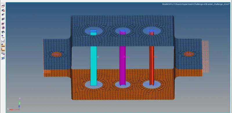
To create a mid surface for a given component and mesh that model. Also, create 1D elements for that component with a given cross-section and DOF.
OBJECTIVE:
a. To create Rod element:- with only translational DOF and RBE2 link
Cross-Section: BOX- Dimension a= 12 mm
dimension b=10 mm
Thickness t= 0.75 mm
b. To create Beam element:- with all DOF and RBE3 link
Cross-Section: I Section- Dimension a= 8 mm
Dimension b= 10 mm
Dimension c= 8.5 mm
Thickness t1= 0.75 mm
Thickness t2= .6 mm
Thickness t3= .6 mm
c. To create a Bar element:- with only x and y DOFs With RBE3 link
Cross-section: CROSS section- Dimension DIM1= 5 mm
Thickness DIM2= 1.2 mm
Dimension DIM3= 10 mm
Thickness DIM4= 1.2mm
d. & e. apply the mass of magnitude 10 with RBE2 link
f. Join the two components with Spring elements
THEORY:
RBE2 Panel :
A rigid element is an element created in a space between two nodes of a model where a rigid connection is desired. In the RBE2 link, Load will be distributed equally for all nodes.
Rigid link elements can be created with dependent nodes attached to an element as a SET. If a rigid link with a dependent node-set is deleted, the associated node-set is also deleted. If the dependent node-set in any panel is deleted, the connected rigid link element is also deleted. Dependent node sets are automatically created when rigid link elements are created. A node-set created in the Sets panel can be connected as a set of dependent nodes to a rigid link element independent node.
RBE3 Panel:
RBE3's are interpolation constraint elements, where the motion of a dependent node is defined as the weighted average of the motions of a group of independent nodes. The dependent degrees of freedom and weighting factors can be specified or automatically calculated based on the geometry
RBE3's are typically used to distribute loads applied to the dependent node amongst the selected independent nodes. In the RBE3 link, Load distribution will be varied.
Masses Panel:
Use the Masses panel to create mass elements. A mass element rests on a node and is used to represent mass.
Rods Panel:
Use the Rods panel to create rod elements. A rod element is an element created in a space between two nodes of a model where rod properties are desired. The two nodes are related to each other based on the properties of the rod element connecting them
Hyperbeam Panel:
Use the HyperBeam panel to create beam cross-section entities that you can use to simplify complex portions of your model into simple bar elements. The HyperBeam panel is arranged into several subpanels. Each subpanel covers a different type of beam section, except for the more general edit section and section utils (utilities) subpanels. It can move freely between subpanels. Working on one subpanel will not be lost if switch to a different subpanel.
Springs Panel:
Use the Springs panel to create spring elements. A spring element is an element created in a space between two nodes of a model where a spring connection is desired.
PROCEDURE:
- First, we want to import the model using import and select the file type as IGES and open the model from the browser tab and select the file as PARALLEL_BRACKET.IGS and click the import option to get the model in the graphical area the selection process is shown below,
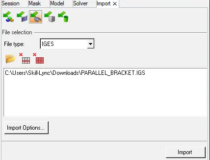
Fig: Import model
- After importing the file an open model will appear in the graphical area and that is shown below,
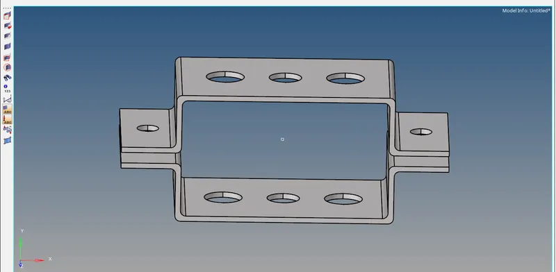
Fig: open model
- Then clean up the geometry manually and check whether the components are connected properly and the surface is filled or not. After checked geometry clean up proceeds with the model to the mid surface by selecting Geom>mid surface> and select the elements that you want to take mid surface.
- In this model, we have two brackets and both are the same as each other while we taking the mid surface for both components with a selection of extraction option as offset+plane+sweeps it will not take proper mid surface in bend portion of that bracket hence we tried other options they are shown as below,

Fig: Extraction option
- After trying other options in extraction we choose the skin offset option and the mid surface is obtained the same as the parent geometry in that bend portion. Hence the skin offset option is selected and they are shown below,

Fig: Extraction option
- Now click the mid surface option after chosen the extraction type and select that component to take the mid surface of that, whereas the selection process is shown below,
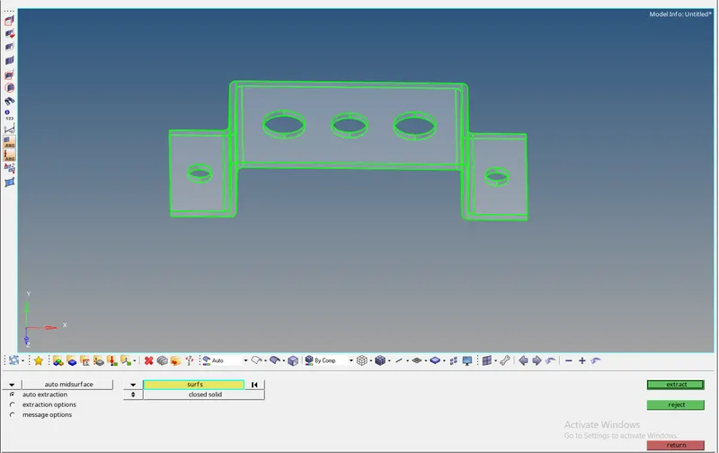
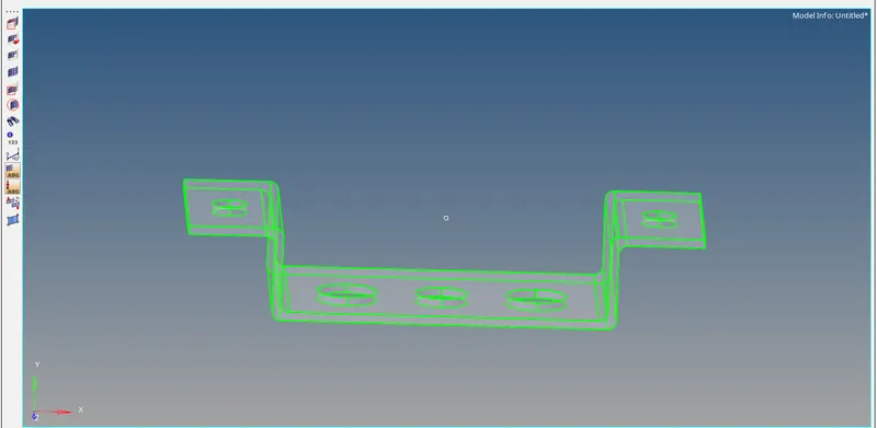
Fig: Mid surface option
- Now the mid surface for two-bracket is obtained and they are shown below,
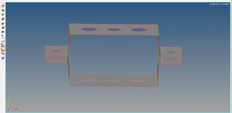
Fig: Mid surface model
The created properties for the two-brackets is shown below,
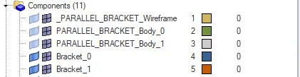
Fig: Components
- We want to create a washer split in the pin to create a good mesh flow near holes. By selecting the Geom>quick edit>washer split and enter the offset values as 5mm and click that hole to create the washer around the hole. A created washer split is shown below,
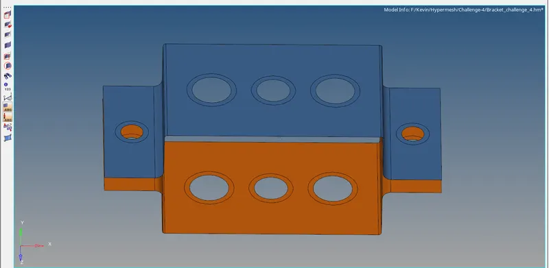
Fig: Mid surface
- Now we want to create Steel Material Card & Property Card for the Parallel Bracket 1 & 2 by using Model>Rightclick>Create>Material & Property option. Assign the Material & Property for Bracket 1 & 2 in the Component.


Meshing:
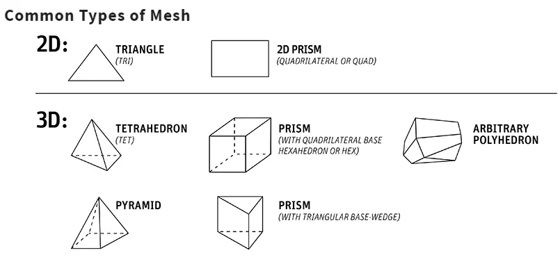
Meshing is an integral part of the engineering simulation process where complex geometries are divided into simple elements that can be used as discrete local approximations of the larger domain. The mesh influences the accuracy, convergence, and speed of the simulation. Furthermore, since meshing typically consumes a significant portion of the time it takes to get simulation results, the better and more automated the meshing tools, the faster and more accurate the solution.
- Now create the mesh for the two brackets by selecting 2D>automesh>enter element size as 5mm and select the surface to create mesh on that surface. The selection process is shown below,

Fig: Auto mid surface option
- Therefore the two components have meshed with the element size of 5mm and the meshed brackets are shown as below,
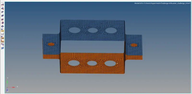
Fig: Meshed component
- Now the quality index is checked by selecting the 2D>quality index and there are no quality criteria is affected in this mesh. This checking process for the model is not necessary because the quality criteria parameters are not given by the instructor. The checking process is shown below,
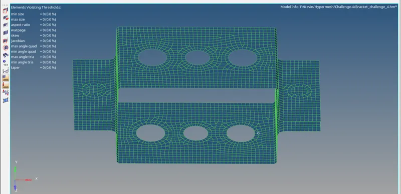
Fig: Quality index
- During mesh the trias are formed in that component so we want to minimize the trias percentage by removing the trais, here we removing the trais by using clean-up tools that are present in the quality index. By using drag tria element, combine tria element, and smooth options we eliminate the trais in that mesh. A selection option is shown below,

Fig: Clean up tools
- After completing the mesh to create rigid in the required portion(a) with the recommended rigid. For rod element, we want to create a rigid RBE2 link by selecting 1D>rigids and select the nodes (by path selection) with only translational DOF and click create. The rigid selection and DOF picked for that rigid is shown as below,

Fig: Rigid for rod
- The same process has to be followed for beam also, to create rigid in the required portion(b) with the recommended rigid. For beam element, we want to create a rigid RBE3 link by selecting 1D>rigids and select the nodes (by path selection) with all DOF and click create. The rigid selection and DOF picked for that rigid is shown as below,

Fig: Rigid for beam
- The same process has to be followed for the bar also, to create rigid in the required portion(c) with the recommended rigid. For beam element, we want to create a rigid RBE3 link by selecting 1D>rigids and select the nodes (by path selection)with only x and y DOFs and click create. The rigid selection and DOF picked for that rigid is shown as below,

Fig: Rigid for bar
- Hence we created the rigid for a,b,c is referred to as rod, beam, and bar, and the rigid RBE2 and RBE3 is shown as below,
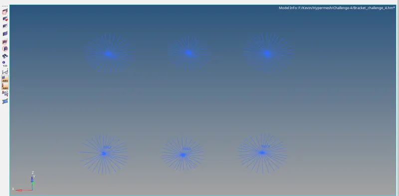
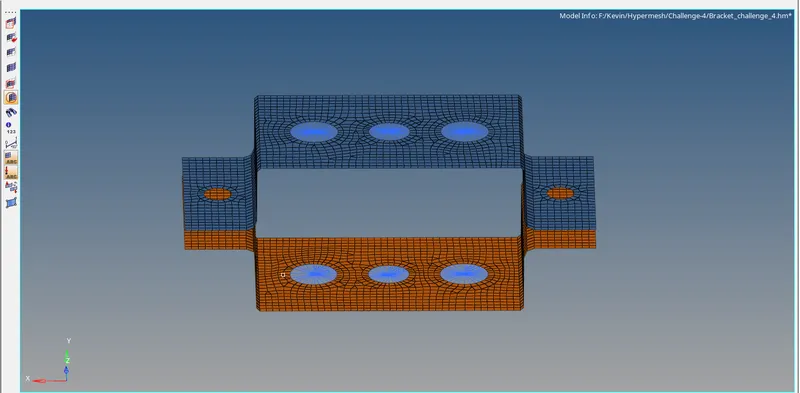
Fig: Rigids (RBE2) and (RBE3)
- Now assign the values for rod, beam, and bar using hyper beam option in 1D and select the standard section as hyper beam and click create an option to open in hyper beam view. Right-click in hyper beam view and create>standard selection>hypermesh>thin walled box and assign the values of Cross-Section: BOX as Dimension a= 12 mm dimension b=10 mm Thickness t= 0.75 mm. Therefore the cross-section values for a rod is assigned and they are shown as below,

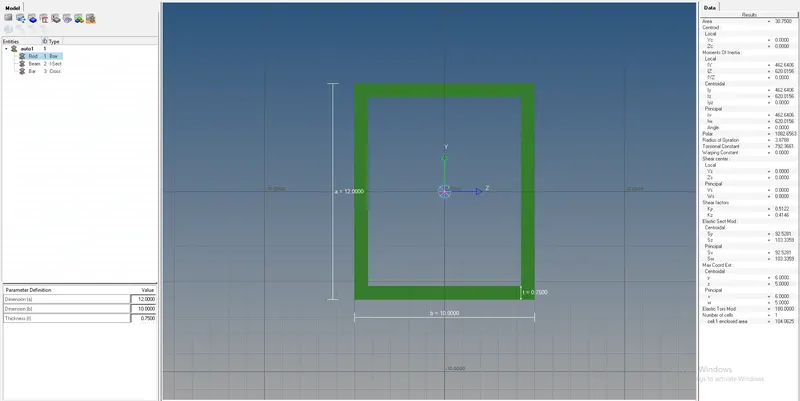
Fig: Rod creation in hyperbeam
- Then assign the values for beam using hyper beam option in 1D and select the standard section as hyper beam and click create option to open in hyper beam view. Right-click in hyper beam view and create>standard selection>hypermesh>standard I selection and assign the values of Cross-Section: I Section- Dimension a= 8 mm
Dimension b= 10 mm
Dimension c= 8.5 mm
Thickness t1= 0.75 mm
Thickness t2= .6 mm
Thickness t3= .6 mm
-
Therefore the cross-section values for a beam is assigned and they are shown as below,
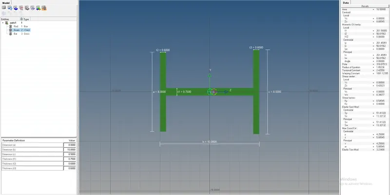
Fig: Beam creation in hyperbeam
- Then assign the values for bar using hyper beam option in 1D and select the standard section as optirstruct and click create option to open in hyper beam view. Right-click in hyper beam view and create>standard selection>optistruct>CROSS and assign the values of Cross-section: CROSS section- Dimension DIM1= 5 mm
Thickness DIM2= 1.2 mm
Dimension DIM3= 10 mm
Thickness DIM4= 1.2mm
- Therefore the cross-section values for a beam is assigned and they are shown as below,

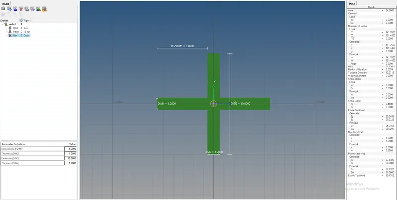
Fig: Bar creation in hyperbeam
- After assigning the values of cross-sections rod, beam, and bar to connect the rod in that position of a by selecting 1D>rods>change the property as a rod that we created before, select the element type as CROD and finally select the two nodes in bracket1 and bracket 2 to connect the rigid as rod and the selection process is shown as below,

Fig: Rigid (CROD) option
- The same process has followed for beam also, to connect the beam in that position of b by selecting 1D>bars>select the property as a beam that we created before, select the element type as CBEAM and finally select the two nodes in bracket1 and bracket 2 to connect the rigid as beam and the selection process is shown as below,

Fig: Rigid (CBEAM) option
- The same process has followed for the bar also, to connect the bar in that position of c by selecting 1D>bars>select the property as a bar that we created before, select the element type as CBAR and finally select the two nodes in bracket1 and bracket 2 at a position of c to connect the rigid bar and the selection process is shown as below,

Fig: Rigid (CBAR) option
- Hence the rod, beam, and bar is created with the recommended assigned values and that 1D traditional element representation is shown as below,
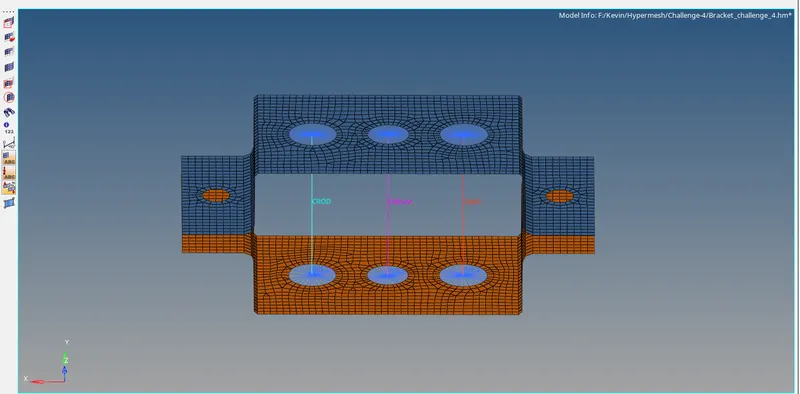
Fig: Cross-section with 1D traditional element
- To visualize the three cross-sections in the form of 2D elements with the assigned dimensions by selecting elements toolbar >2D detailed element representation the process is shown below,

Fig: 2D detailed element representation
- A 2D detailed element representation of rod, beam, and bar is shown below,
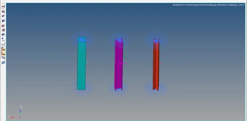
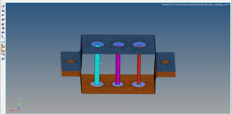
Fig: Cross-sections
d. & e. apply the mass of magnitude 10 with RBE2 link
- Now apply the mass of magnitude 10 in the position of d & e in that brackets by using rigid as RBE2 link. To create the rigid by selecting 1D>rigids and select the nodes (by path selection) with all DOF and click create. Hence the rigid RBE2 will create and apply the mass to that rigid by selecting 1D>masses>pick the node in that rigid and enter the mass value as 10. Select the element type as CMASS1 and click the create option. The mass is added at the position of d&e and they are shown as below,
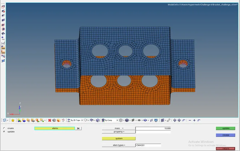
Fig: Added mass
f. Join the two components with Spring elements
- To join the two brackets at the position of (f) with spring elements by selecting 1D>spring and select the two nodes in between the two brackets and assign the property as spring. Select the element types as CELAS1 and click the create option. The created spring and their selection process is shown below,
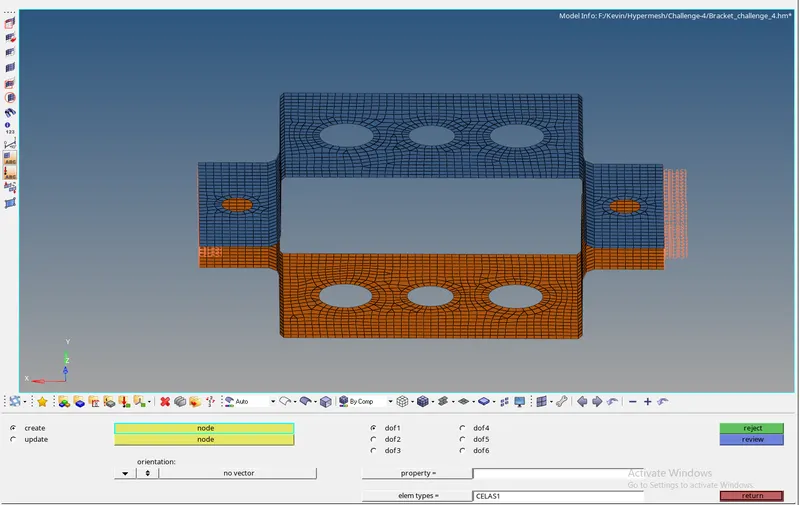
Fig: Spring creation
- The properties for brackets, rigids, rod, beam, bar, spring, and the material card as steel is shown below,
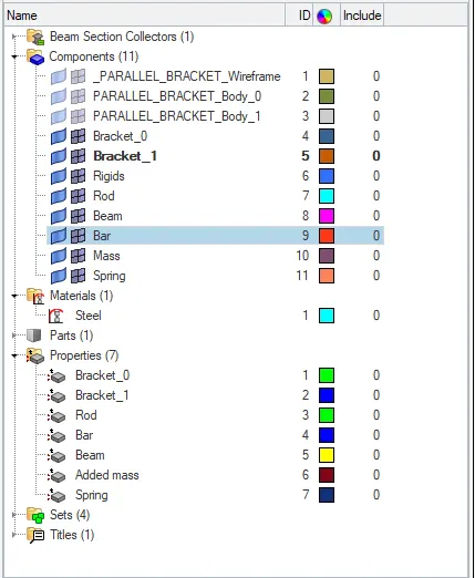
Fig: Properties
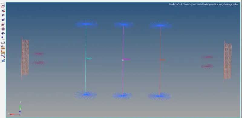
- Here the below image shows the rigid in the position of a,b, and c that is connected with rod, beam, and bar. And a rigid of RBE2 in the portion of d and e with added mass and finally springs that connected with the two brackets at the position of f.
CONCLUSION:
Hence created 1D elements on the given component with given cross-section and DOF has been created.
a - Rod element Created with only translational DOF and RBE2 link.
b - Beam Element Created with all DOF and RBE3 link.
c - Bar Element Created with only x & Y DOF and RBE3 link.
d & e - Mass added on the Master node of RBE2 link.
f - Two Components were joined with Spring Elements.