Assignment 1
AIM:
To check the geometry cleanup, extract midsurface and to do 2D meshing for given three components they are practice model, clip repair, mounting bracket.
OBJECTIVE:
- To write a detailed report on the 2D meshing process and also mention which method we used to extract the mid-surface.
SOFTWARE USED: HYPERMESH (Radioss).
QUALITY CRITERIA TO BE FOLLOWED:
- There should not be any free edges, to convert all of them into refine geometry.
- Create 2D mesh with target length = 5mm, Min length = 3.5mm, and Max length = 7mm
- And assign proper thickness by creating a generic property.
1. Target element length:
It is the size of the element by which we can get the most nearer approximate value of the result compared to the experimental result.
2. Minimum element length:
The minimum element length is given by the instructor for the reason of quality criteria to avoid the presence of any zero-length element. It is very important to check for crash analysis.
3. Aspect ratio:
The aspect ratio is defined as the ratio of maximum element edge length to the minimum element edge length. The ideal value for aspect ratio is 1 but less than 5 is acceptable.
4. Wrap angle:
Wrap angle is defined as the angle between normal of the two planes by splitting the quad elements along the diagonal. Therefore the maximum angle allowed between the two possibilities is called the wrap angle. The ideal value is 0 degree but less than 10 degree is acceptable for good practices.
The wrap is not applicable in the triangular element.
5. Skewness:
If the quad element is not square and has deformation then the skewness defined as the minimum angle between the two lines joining the opposite mid sides of the element similarly for the triangular element it is 90 minus between the line from each node to the opposing mid-side. The ideal value is 0 but less than 45 degree is acceptable.
6. Jacobian:
Jacobian is the scale factor used in the transformation of a co-ordinated system. This is used for a faster analysis point of view. The ideal value is 1 but greater than 0.6 is acceptable.
It is global to the local coordinate system.
BASIC SHORTCUTS REQUIRED:
To Rotate component: Press & Hold + ctrl and first mouse button pick hold
To Drag component: Press & Hold + ctrl and right mouse button pick hold
Zoom: Press & Hold + ctrl and scroll middle mouse button for zoom in and out
To measure distance: Press F4
To delete the surface or elements: Press F2
Mask command: Press F5
Quick Geometry edit: Press F11
Surface edit features: Press shift + F9
Meshing window: Press F12
To check for connectivity: Press shift + F3
To check the elements: Press F10
PROCEDURE:
- Import the CAD file geometry into the Hypermesh software.
- Clean the geometry.
- Extract the midsurface and clean up midsurface geometry.
- Now create 2D mesh and the quality criteria should be followed.
- To assign proper thickness, by creating generic property.
STEP-1:
IMPORTING CAD GEOMETRY:
- In first step we want to import the CAD geometry into the hypermesh software by selecting the File>import>model>geometry>select file name>click import option.
- The downloaded geometry will displayed in the screen, now save the model by using save as option in the file menu Click File>save as>model. An imported three parts are shown as below,
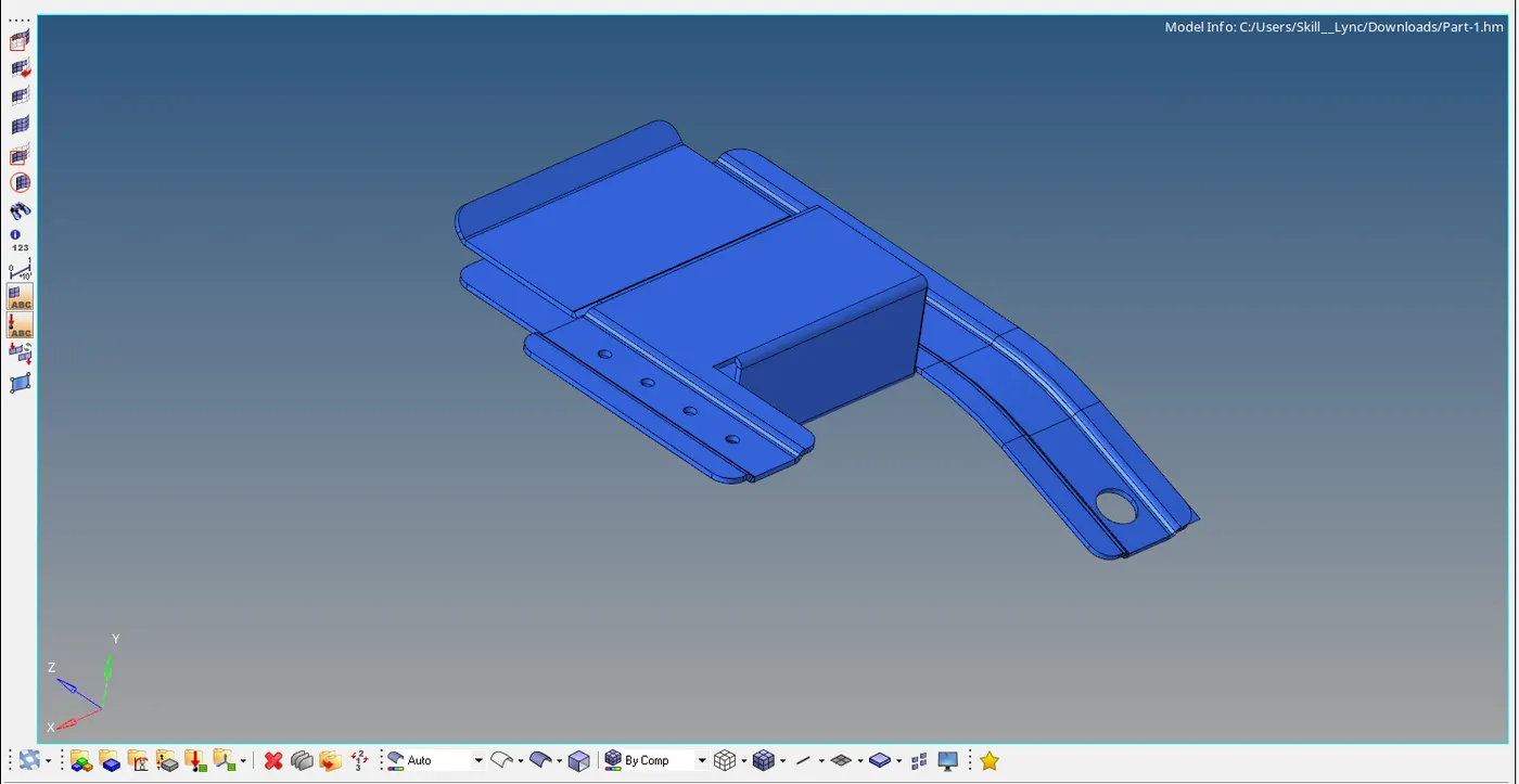
Fig:Part-1
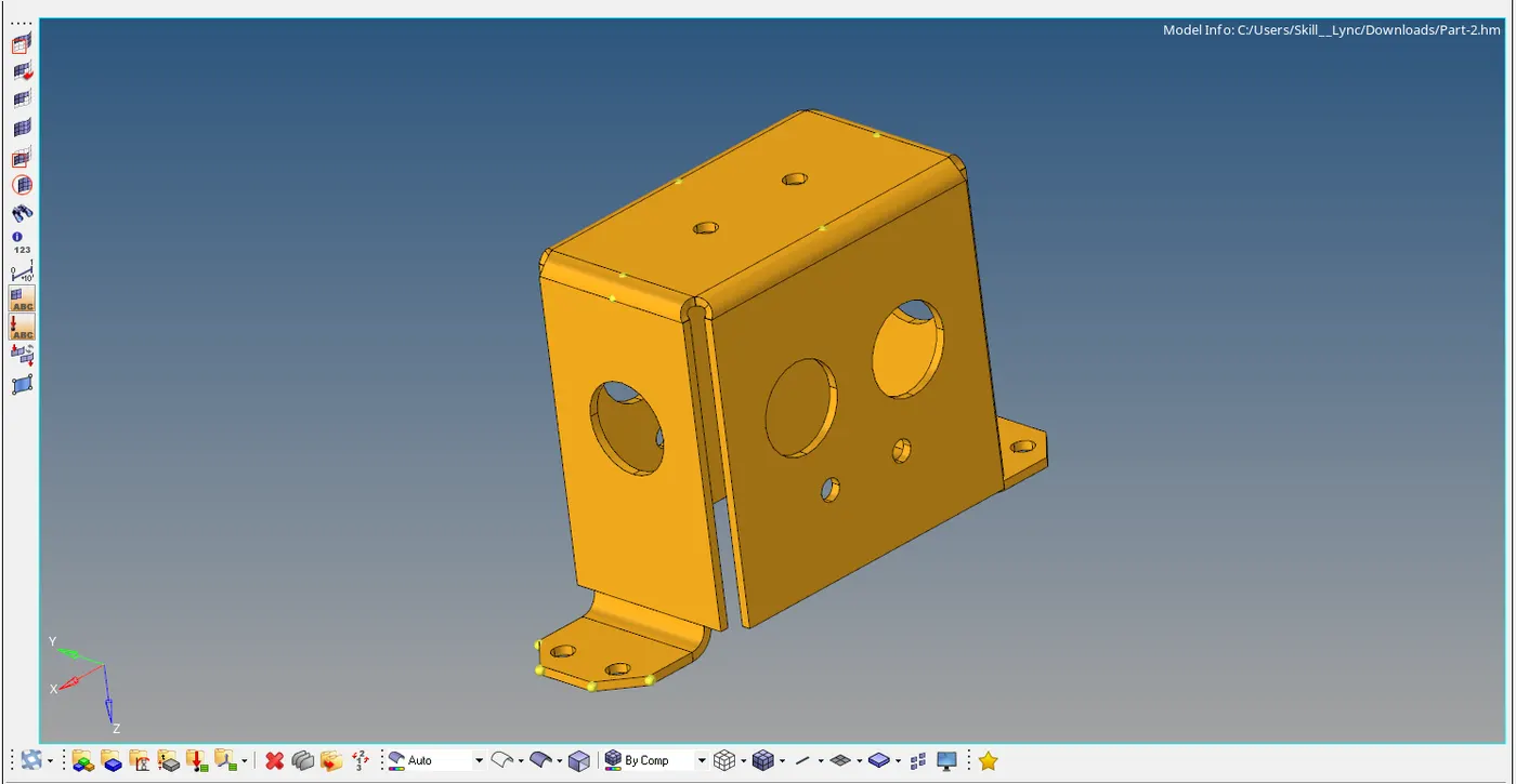
Fig:Part-2
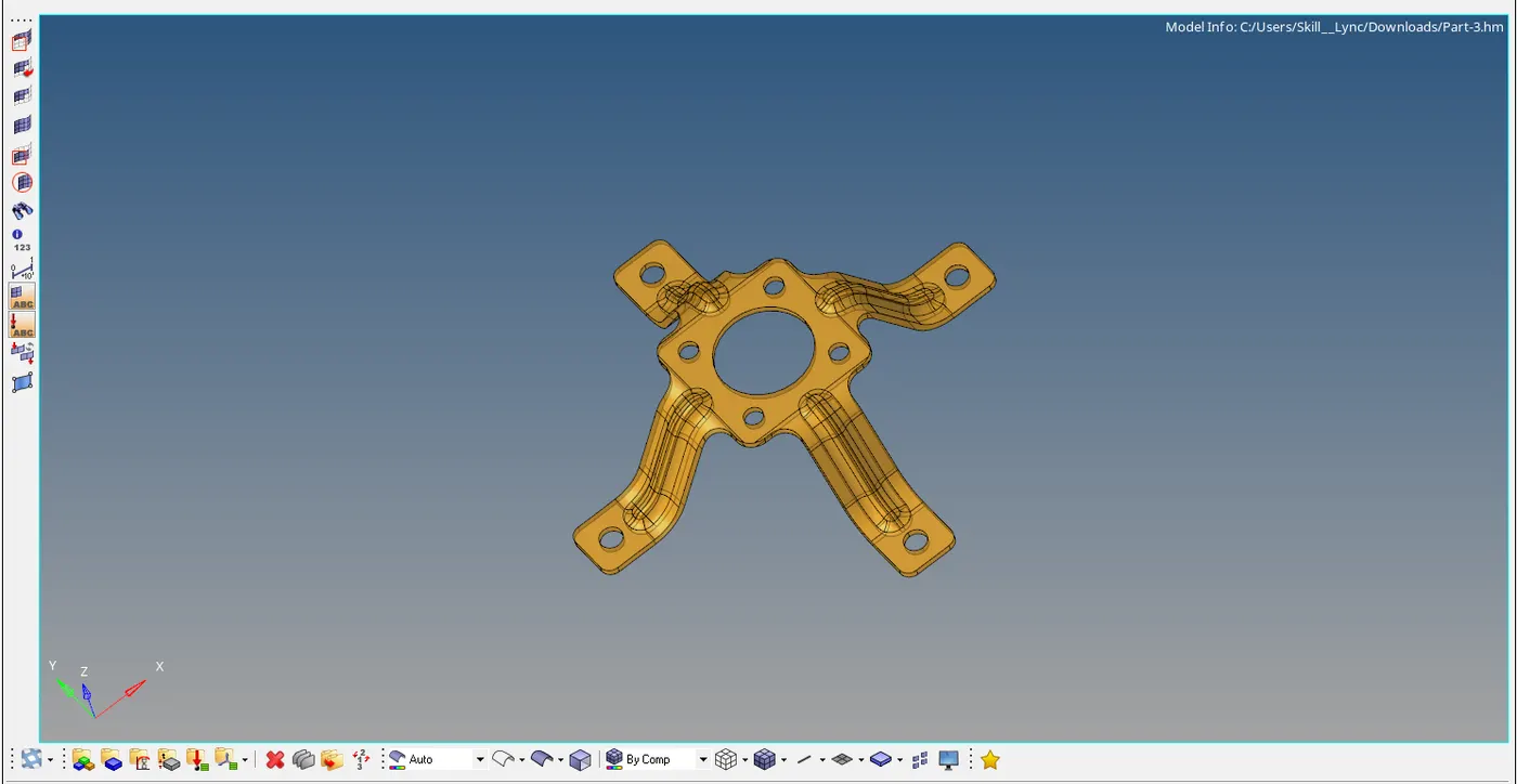
Fig:Part-3
STEP-2
GEOMETRY CLEANUP:
- After importing the model we want to clear the geometry clean up in that model. A geometrical errors will lead to change in geometry it will also affect the mid surface and mesh.
- Geometry cleanup is performed to make sure that there are no free edges, duplicate faces, or any surface void in the model and no unwanted extended surface.
- During the geometry clean up errors are identified and rectified by using some of tools in the hypermesh software. The geometric errors in part-1 model are shown as below,
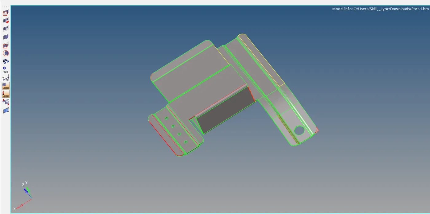
Fig:Part-1(Geometric errors)
Error-1
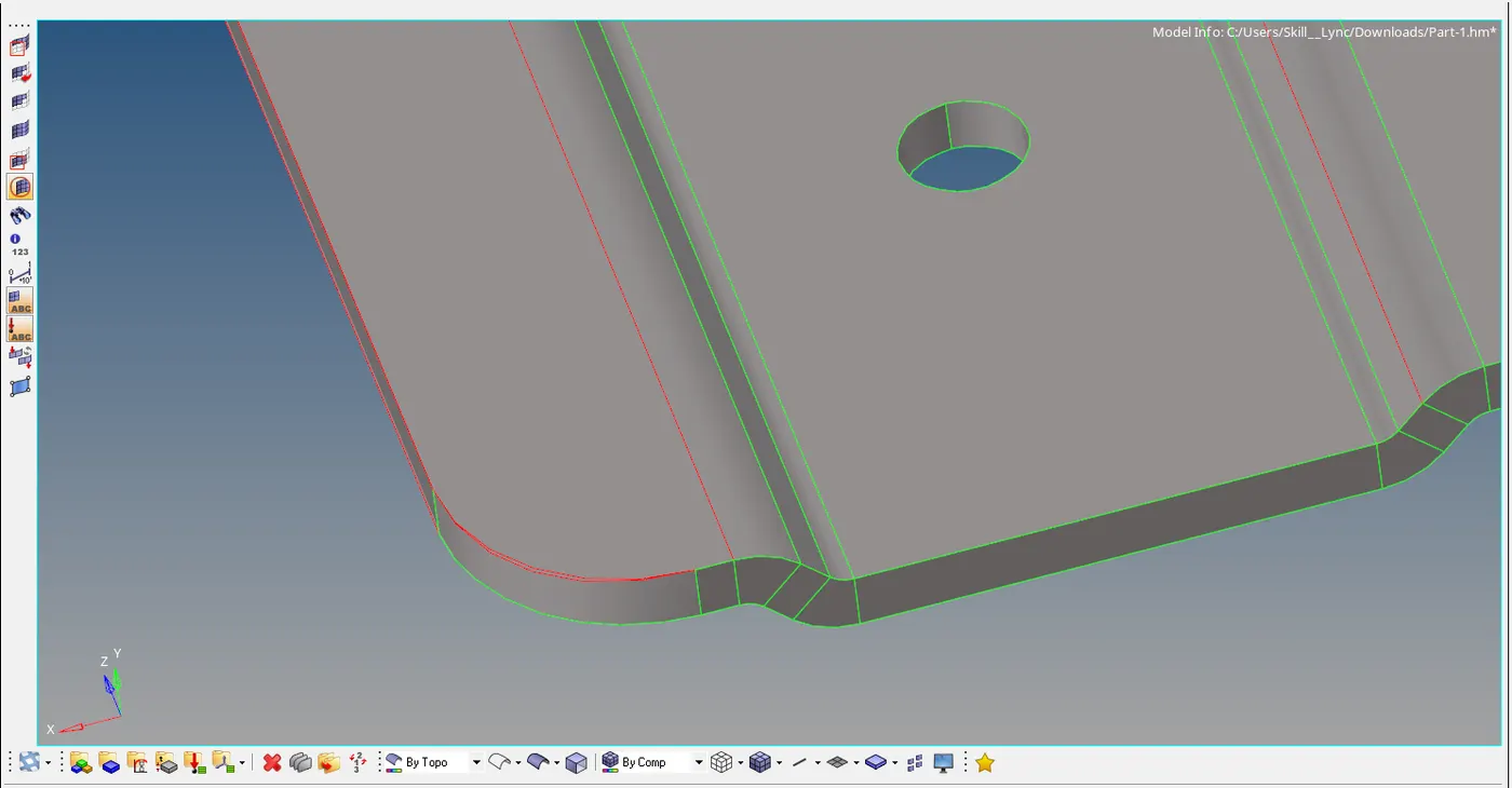
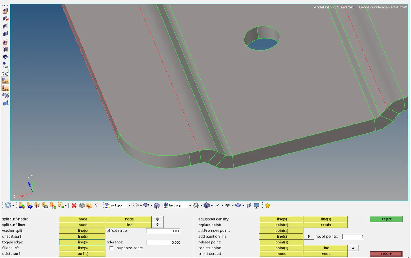
This error is cleared by using the toggle option which is present under the Geo>quick edit>toggle edge the toolbar. By selecting this option and initate that two lines to get toggle the edge now it seems cleared in that edge of geometry. An cleared area in that part-1 model are shown below,
Error-2
Here the duplicate face are formed over the current surface that indicates yellow line in that area. To confrim that check with the mask option present in the toolbar.
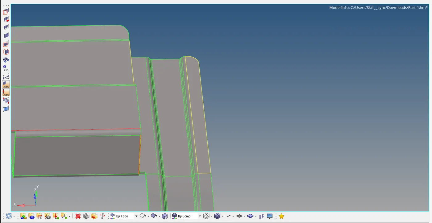
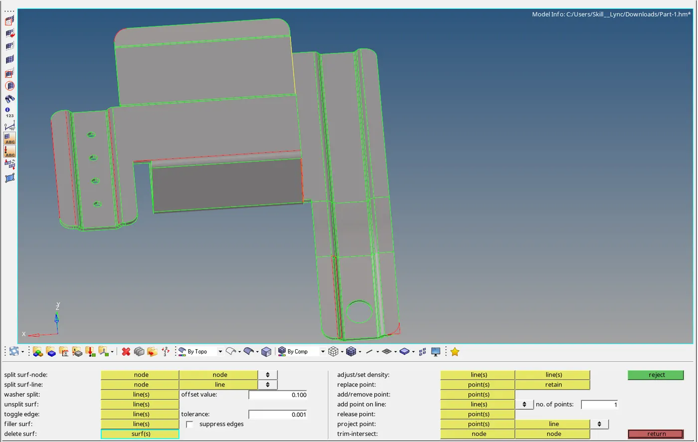
We need to delete the overlapping or duplicate face by selecting the F2>Select the duplicate face and delete or click the delete surf option which is present under the Geo>quick edit>delete surf toolbar. By selecting this option the unnecessary surfaces will be deleted. An rectified area in that part-1 model are shown below,
Error-3
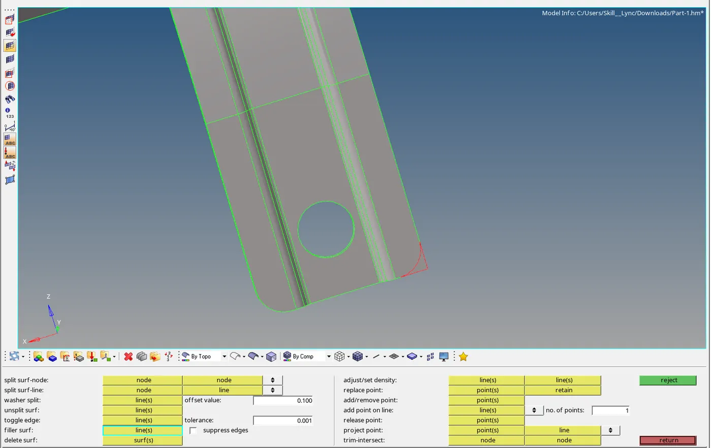
Here the red lines shows that the gap between the two surfaces we need to fill the faces by selecting the filler surf option. Click Geo>quick edit>filler surf then select the two lines to fill that surface.
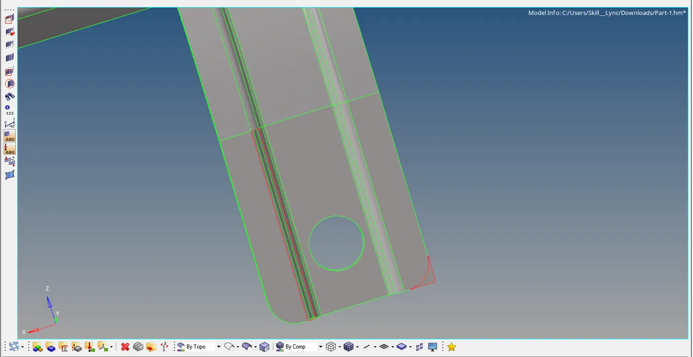
The error is rectified by selecting filler surf option that image is shown below,
Error-4
In this area we want to trim the extended surface to clear the geometry errors.
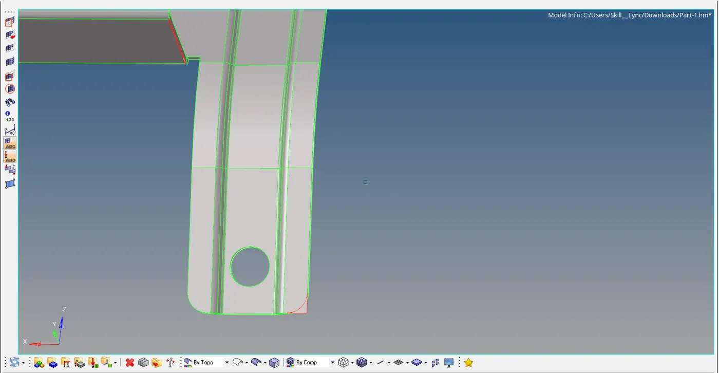
To trim the surface Press shift + F9> under with surf > Select the top surface as first surface selection and the perpendicular surface as the surface 2 and trim the excess surface otherwise select surf edit and select the trim with surf/plane option and select the surfaces.
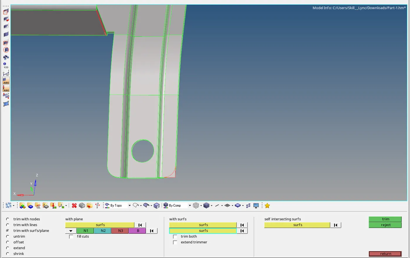
Now excess piece of surface should be deleted by selecting delete option and change the selecting option as surf and delete that piece or press F2 to delete the trim surface. The geometric cleared area in that part is shown as below,
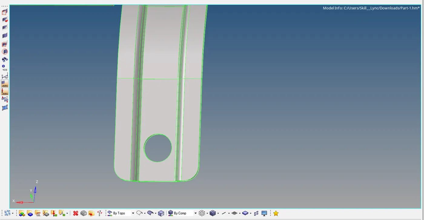
The geometric cleanup image for all the three parts are given below,
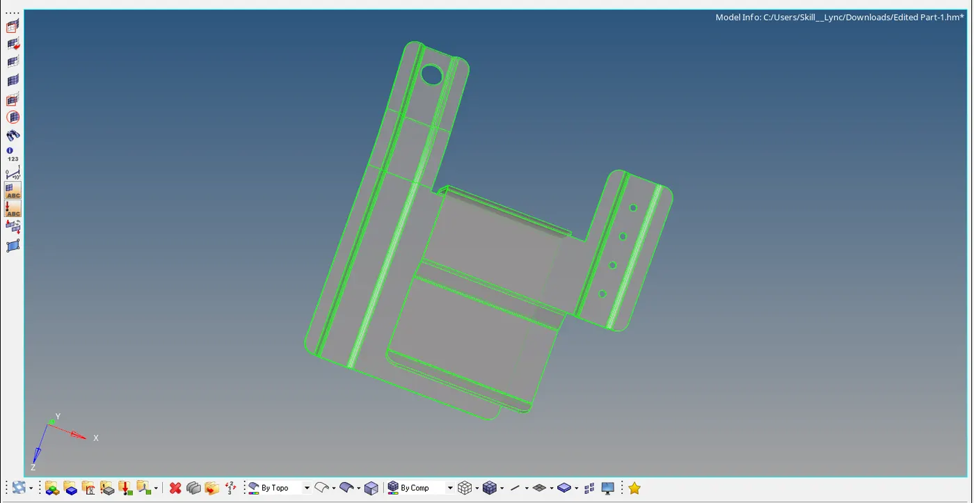

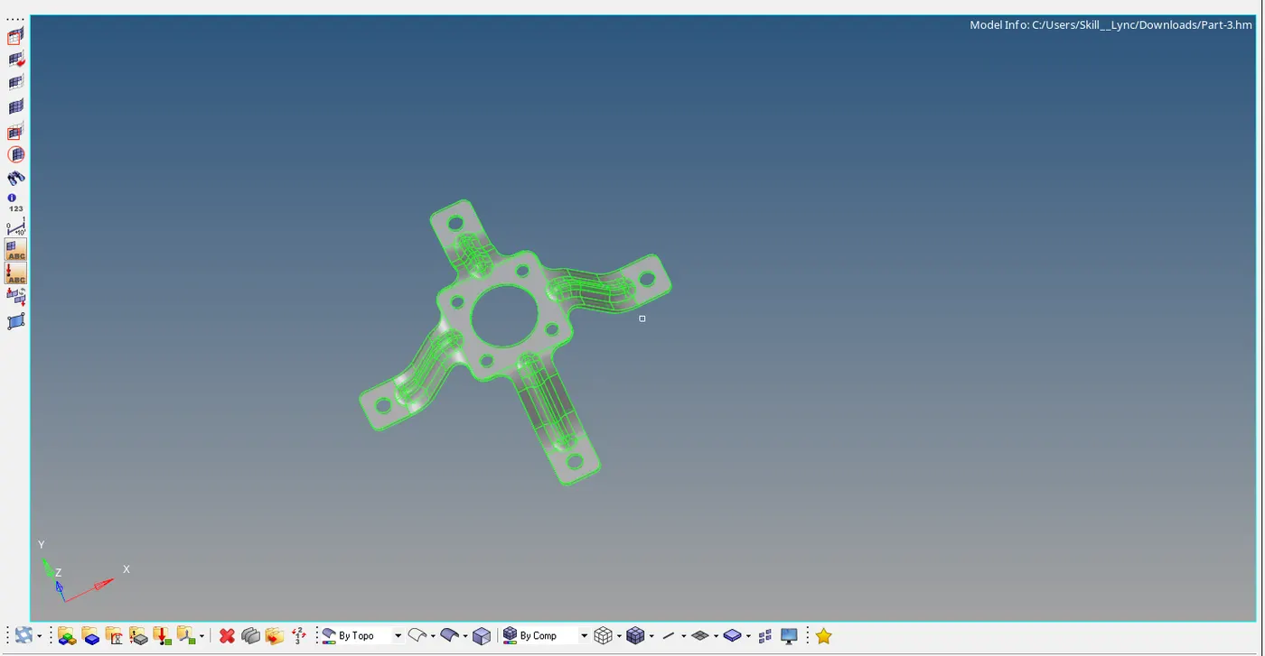
STEP-3
EXTRACT THE MID SURFACE AND CLEAN MID SURFACE GEOMETRY:
- After the geometry is cleaned the mid-surface is extracted from the model, to create mid-surface we need to select the Geometry > mid-surface > auto mid-surface > Select the closed surf > Extract it we also can do offset by selecting the Geometry > surface edit > Offset option.
- An obtained mid surface for each part is shown as below,
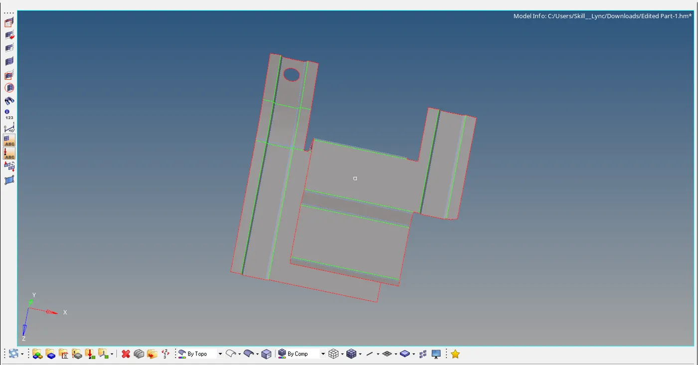
Fig: Part1 - Midsurface
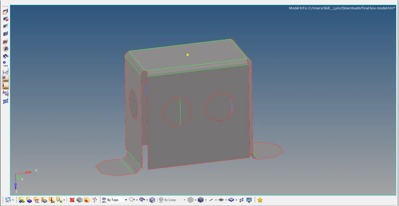
Fig: Part2 - Midsurface
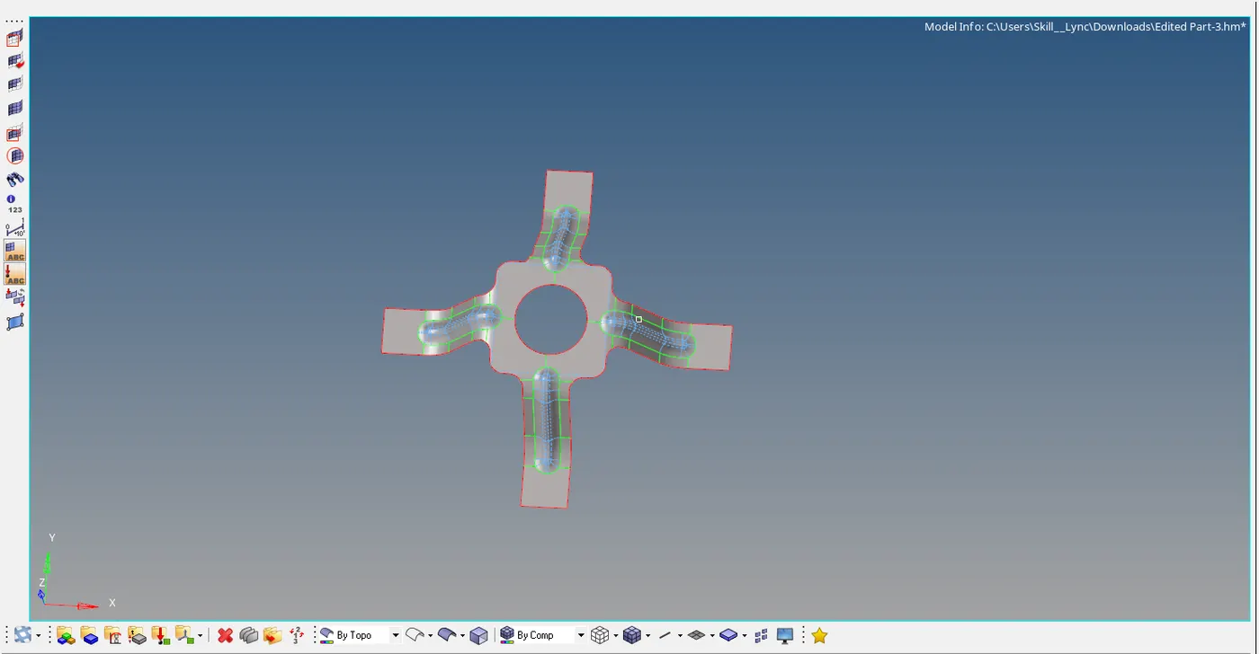
Fig: Part3 - Midsurface
STEP-4
SHELL MESHING & TO ASSIGN THICKNESS:
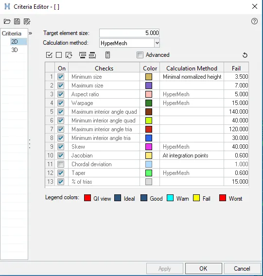
- We want to assign the quality criteria value for meshing purpose that will leads to reduce the failure in minimum and maximum length during meshing. By selecting the option preferences and click the criteria file edit option the dialogbox will displayed and enter the value of minimum and maximum length in that dialog box that are shown below,
- After mid surface is completed we want to mesh the model by selecting th 2D > Automesh and select the element or face that you want to mesh on that and select the element size and give value 5mm as per the question and finally select mesh option. An mesh will be obtained on that part by slecting the auto mesh option. The mesh flow is controlled by increasing and decreasing of mesh density around edges.
- Try to reduce trias if it is possible an that area and make as quad by using some options like split, combine ect. By selecting the 2D>Edit mesh option we find the tools like create, combine and split option that could use to move the trias and also to eliminate the trais. F6 option also used to open for this tools.
- The smooth option will smoothen the area and adjust the element mesh. Once the model has been meshed, the quality of the mesh is checked with mesh criteria i.e minimum size of the element is 3.5mm and the maximum size of the element is 7mm.

- While checking the quality criteria the cleanup tools will help to clear the meshing errors the cleanup tools are displayed below,

- By using these tools in quality index also will helps to clear the trias or to organize the mesh in good flow and to clear from the quality errors.
- After clearing the quality issues the meshing will completed and now we want to assign the thickness foe the mesh.
- To assign the thickness select the tool>organize>desh component>select original component the select the element and changed as displayed option now click move option. Now go to original component and right click on property id option it shows dialog box in that dialog box select edit option and assign the thickness.
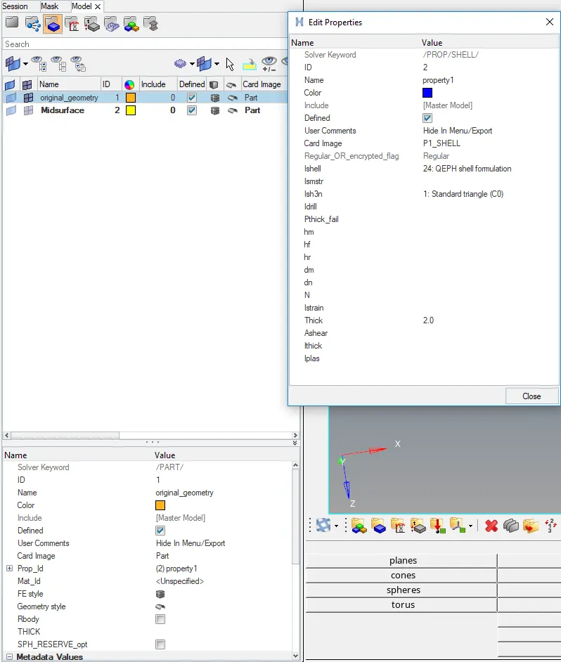
- Since the model has thickness and we have performed 2d meshing, we are supposed to assign the shell property with a thickness of the model and once we assign the property to the model and change visualization to 2d detailed representation you can see the mesh with the thickness you have assigned.
- The meshed and thickness assigned model of three parts are shown below,
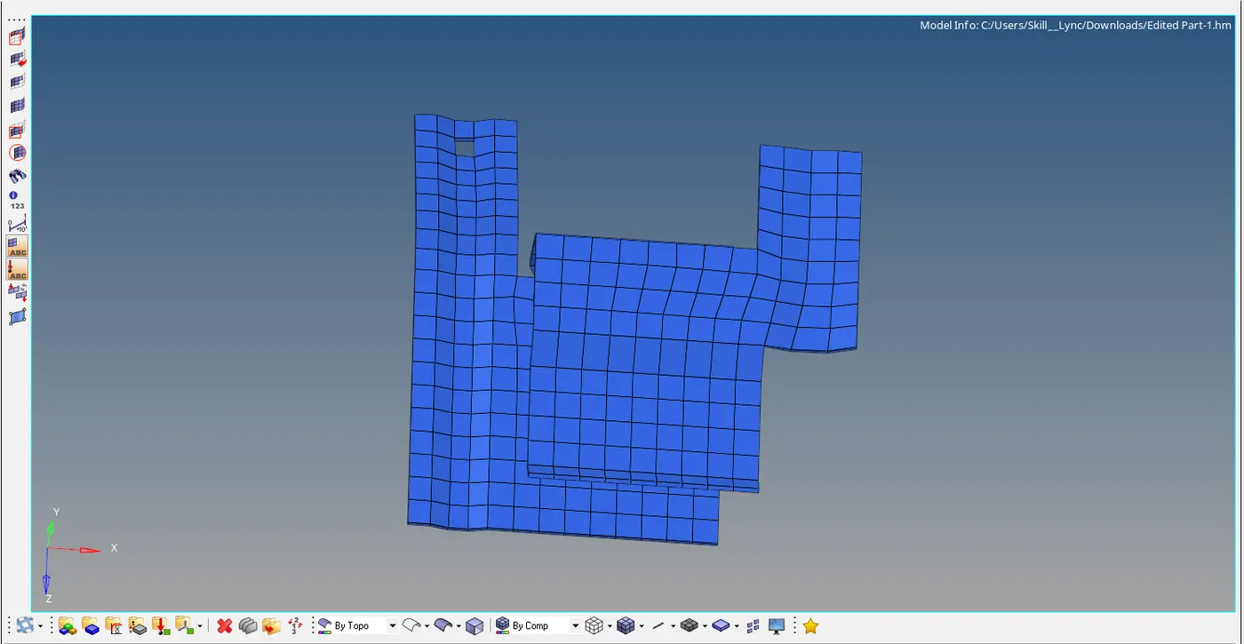
Fig: Part1 - 2D-Meshed and assigned a thickness of 0.9mm
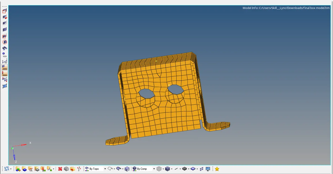
Fig: Part2 - 2D-Meshed and assigned a thickness of 2.0mm
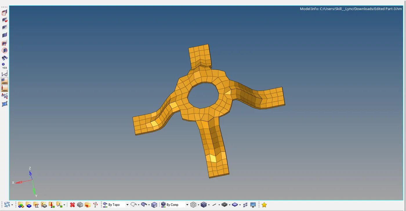
Fig: Part3(Mounting Bracket) - 2D-Meshed and assigned a thickness of 1.8mm
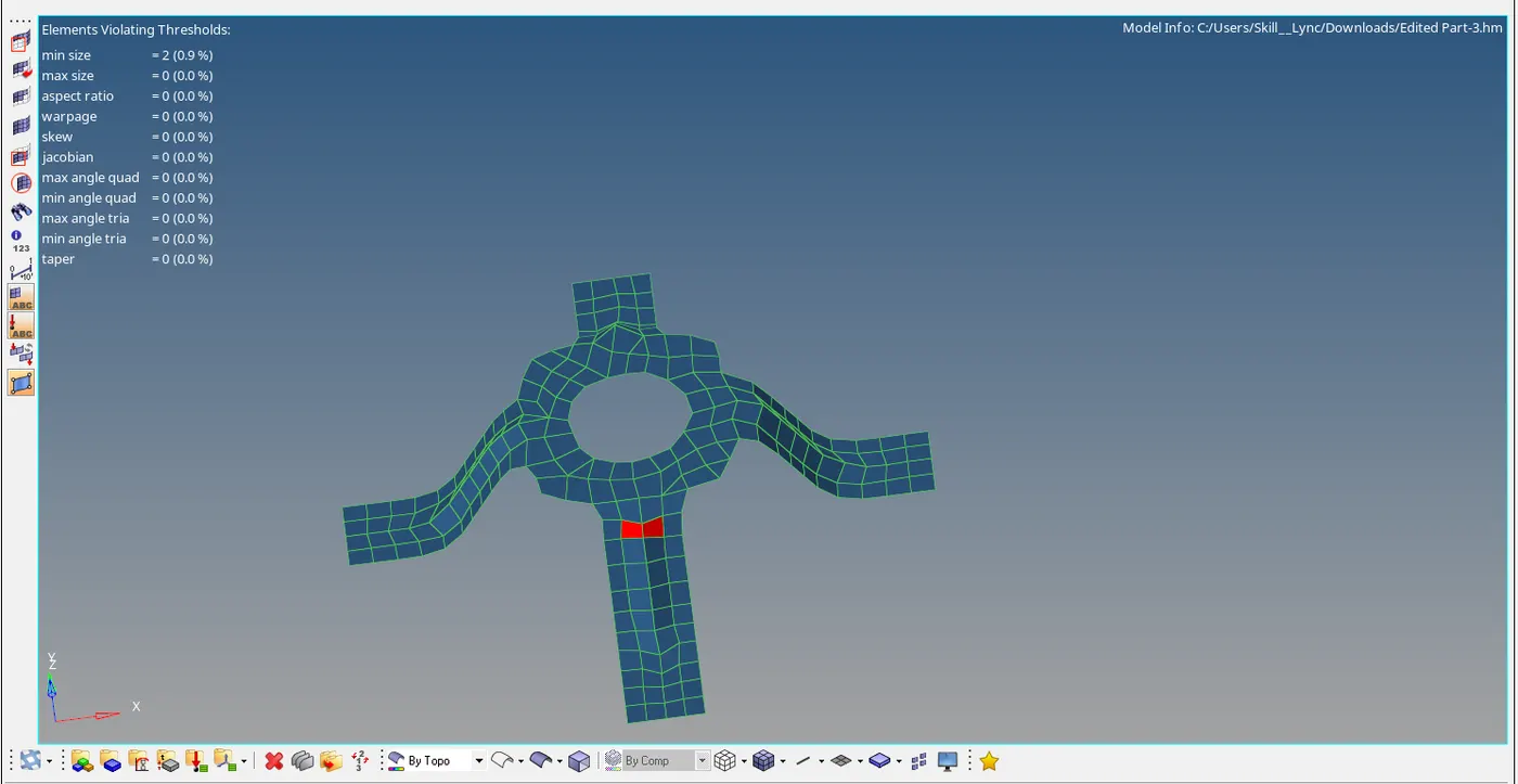
ERRORS OCCURED DURING MESH:
- In this area the minimum size is affected during the meshing process that was cleared by clean up tools in quality index. By executing various options like smooth option, element optimize, node optimize, split quad elements, ect.
- The mesh flow also controlled by these type of tools which could not affect the quality criteria also therefore the error is rectified by this type of method.
CONCLUSION:
Hence geometric cleanup is executed, mid-surface is extracted and meshed with a target element size of 5.0mm. Most of the element size is Between 3.5-7mm except for a few cases where the element size is intentionally failed to best capture the shape of the part and the quality of the element is also checked. Therefore all the three parts are meshed according to the quality criteria and thickness also assigned.