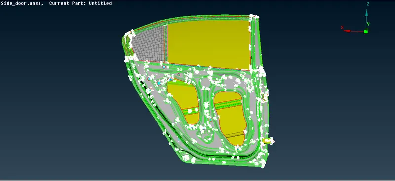
Week 6 - Creating connection for Rear door
AIM:
For the given Rear door FE model, Create and Apply different PIDs for different components and perform suitable connections.
OBJECTIVE:
To connect the different components in the rear door FE model with suitable connections.
SOFTWARE USED: ANSA
PROCEDURE:
Importing the File:
- First, we want to import the given model by using the File>Select the model and click the open option. The selection process is shown as below,
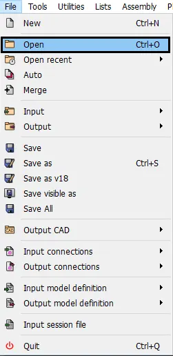
Fig: Open option
- After import, the file the model will appear in graphical area that is shown as below,
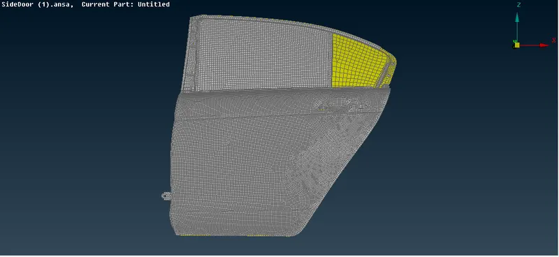
Fig: Open model
Connections:
Bolt Connections:
- In this type of connection, we provide connections to wherever the bolts are going to be fitted in the rear door model i.e. near to attaching hinges in this case. We first create a 3D point near the holes of the bolt connection using the On COG option present in the Points tab of the TOPO module. The selection process is shown as below,
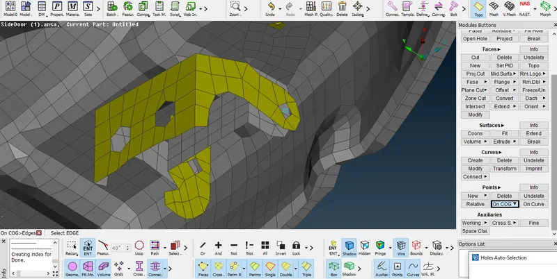
Fig: Open model
- Then we convert the 3D points into bolt washer points using the Convert option present in the Assembly tab as shown in the figure given below,
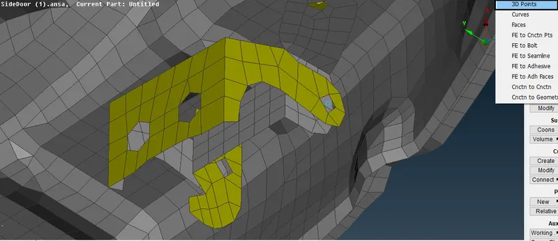
Fig: COG creation
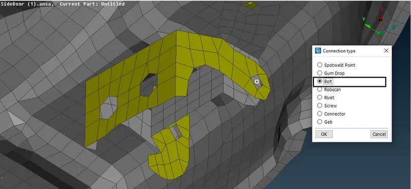
Fig: Connection type
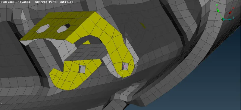
Fig: Bolt converter
- After that, we go to the Connection Manager option present in the Assembly tab and select all washer points and then we press the middle mouse button to get the connection manager tab.
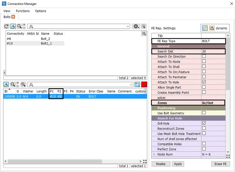
Fig: Connection Manager - Bolt
- We have 3 tabs in the connection manager menu namely connectivity list, connection list, and FE representation settings. We go to the connection list and we proceed to give connection for which all parts we want using F1 tab we go to the model and we select each and every part and press enter to confirm since this model has a single PID we don't need to go every time and select the parts, after confirming the connectivity list tab is also updated based on the connections given,
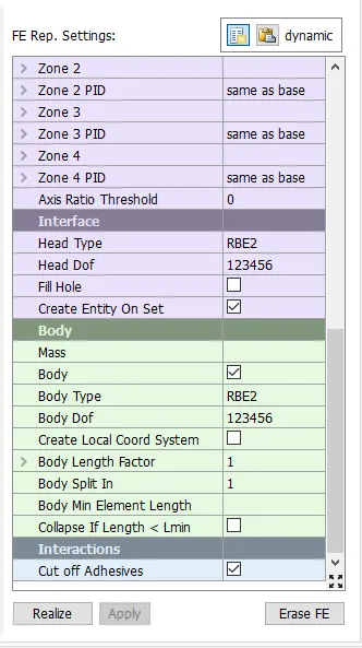
Fig: Connection Manager - FE rep Settings
- Finally, we go to the FE representation tab and under it, we provide the FE representation type as Bolt and then we provide the zones to be attached as In/Out so that all the zones inside the bolt connections get rigidly fixed. We apply all the settings and click on Realize option. The connection manager tab is shown in the figure is given below,
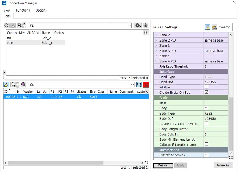
Fig: Connection Manager - Bolt
- We, finally obtain the bolt connection in which all the nodes nearing the boundary of the bolt connections are connected using RBE2 and their vertical connection between these connections as shown in the figure given below,
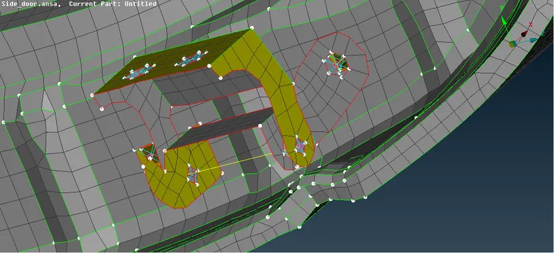
Fig: Bolt Connection
SpotWeld Connection :
- To create a spot weld connection select Topo>Points>On COG option and select edge to create a point. The selection process is shown as below,
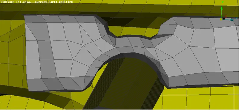
- After Creating a point, Go to the Convert option and select a point and Select a Spot Weld Point connection type they are shown as below,
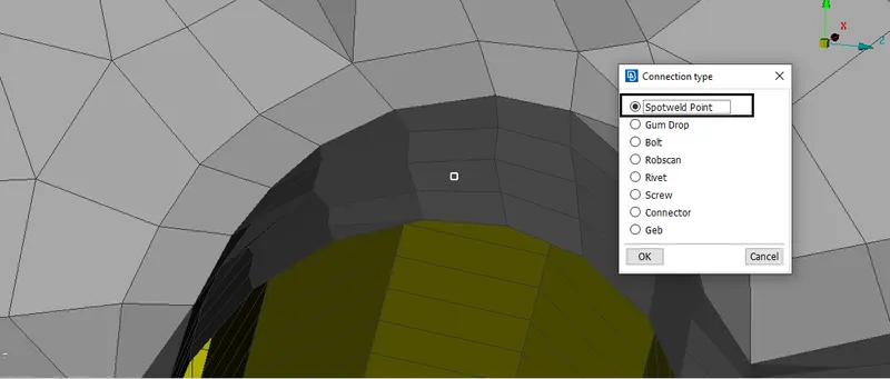
Fig: Connection type
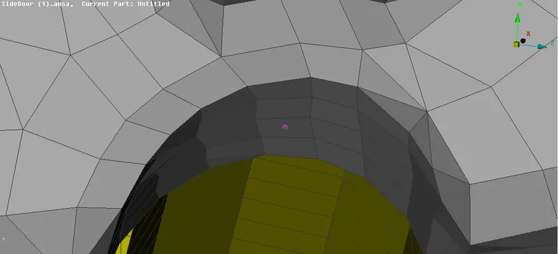
Fig: Spotweld converter
- Go to the Connection option and Select the Spot Weld point and Click ok, Connection Manager window will open.
- In the Connection Manager window, select the part to make a connection and set it as FE Rep type as RBE3-HEXA-RBE3, Search Distance as 20. The connection manager with settings are shown below image,
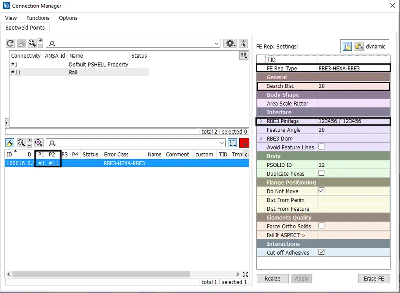
Fig: Connection Manager - Spot Weld
- Set constraint in all DOF and Create PSOLID property and click apply & Realize.
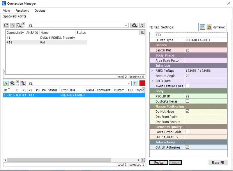
Fig: Connection Manager - FE settings
- Now the spot weld is created and that is shown as below,
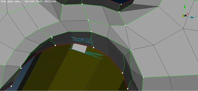
Fig: Spotweld Connection
CBUSH Connection :
- Now go to Mesh>Perimeters>Feat2curve option and select the edges and create a curve.
- After creating a curve, Go to the Convert>curves option and select a curve and convert to a Spot line. The created curve for Cbush connection is shown as below,
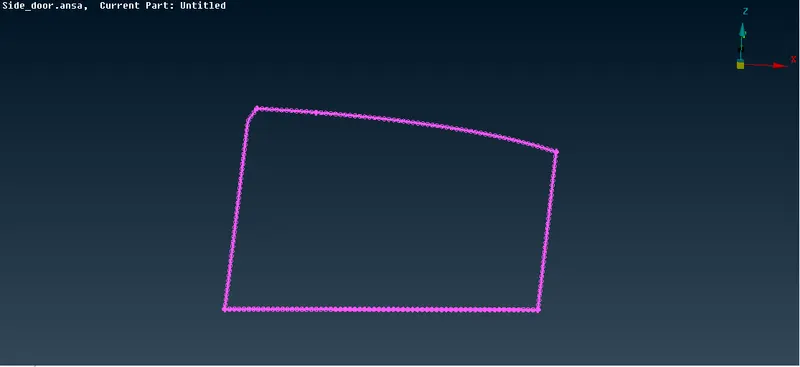
Fig: Converting Curve into Spot line
- Go to the Connection option and Select the Spot Weld point and Click ok, Connection Manager window will open.
- In the Connection Manager window, select the part to make a connection and set it as FE Rep type as RBE3-CBUSH-RBE3, Search Distance as 30 and Select Keep all Branches option. The connection manager with settings are shown below image,
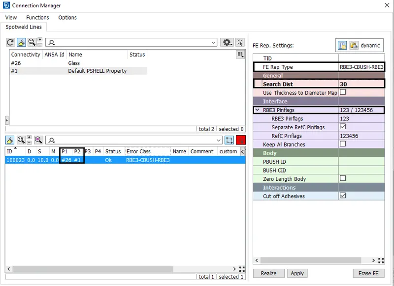
Fig: Connection Manager - CBUSH
- In the Connection Manager window, Create a PBUSH ID and assign the values for the property as per the instructor shown in the videos. They are shown as below,
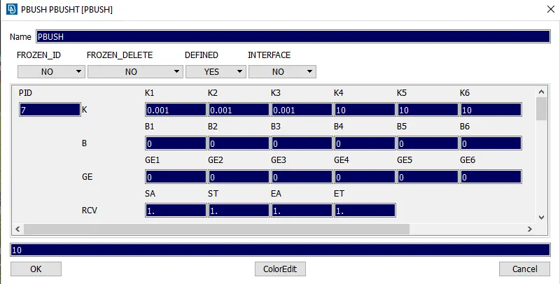
Fig: Creating PBUSH
- After setting all in the connection Manager window, click apply & Realize.
- After creating a CBUSH, Open the CBUSH window from Database and convert Orient as with Cord & CID as 0 for all CBUSH.
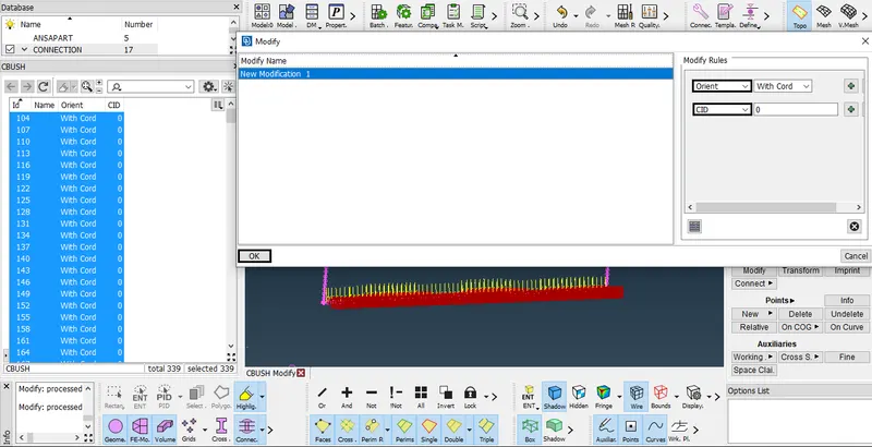
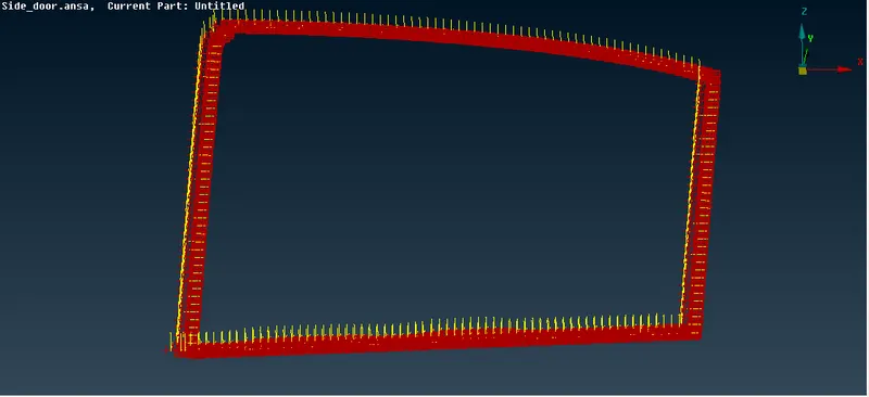
Fig: CBUSH Modifying Orient & CID
- Finally, CBUSH will be created along with the Global axis.
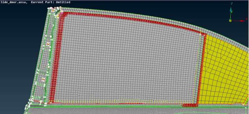
Fig: CBUSH Connection
RBE2 Connections (Door Handle):
- In this type of RBE2, we provide connection in the door handle by providing the spider connections of two holes of the door handle and then connecting the two master nodes of the two spider connections to form a centroid or COG. Then we provide the Con mass for the COG point using the Nodes option present in the CONM2 in CONMi option in the elements tab of NASTRAN module as shown in the figure given below,
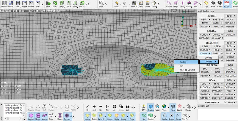
Fig: RB2 Connection selections
- Then in that tab we provide the COG mass as 100gm, we the values of mass in tonnes i.e. 100gm= 1e-4 tonnes in that tab as shown in the figures given below,
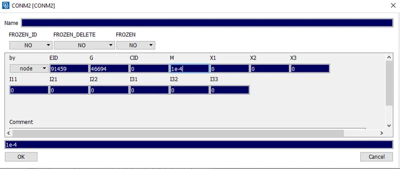
Fig: RB2 Added mass
- Hence created RB2 connection and added mass value is shown as below,
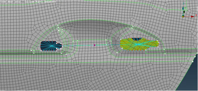
Fig: RB2 Connections
RB2 Connection:
- In this type of RBE2, we provide a connection to one hole which is present on the model to make it rigid in all the axes which avoids movement of it during the noise, vibration, and harness simulation in NASTRAN.
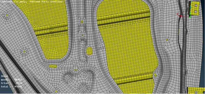
- Now select NASTRAN DECKS>Elements>RBE2>Many nodes Option and select the nodes and Create an RBE2 connection.
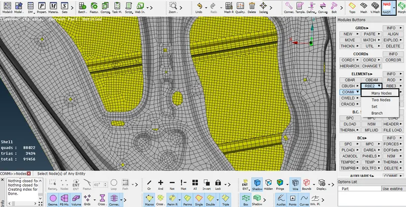
Fig: RB2 Connection selections
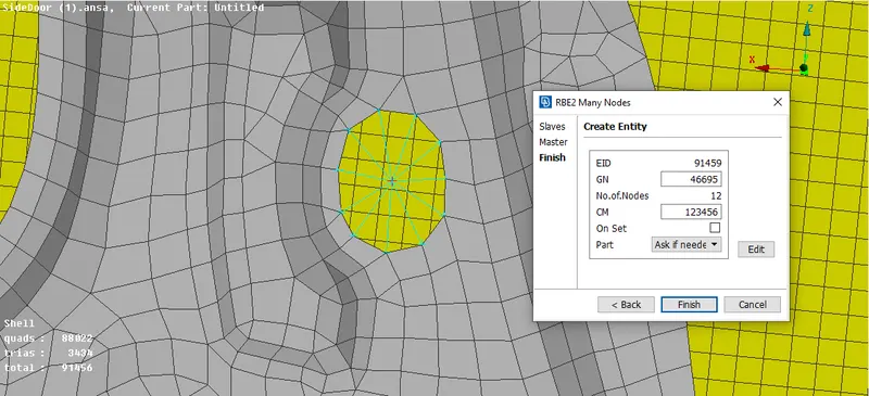
- We should go to the NASTRAN module and under the elements tab, we select the RBE2 option. We provide these types of connections where there are independent holes present, Connect all other parts by using RBE2 connection as shown in the figure given below.
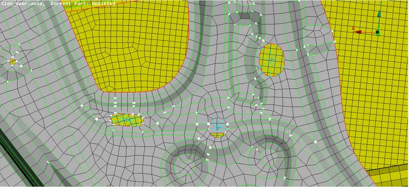 Fig: RBE2 Connection
Learning Outcomes :
- To identified how to create a Bolt Connection, Spotweld Connection, CBUSH Connection, and RBE2 Connection.
- Learned to create and apply PID for different FE Components.
RESULT :
Hence the PIDs for side door FE model is created and the connections like Bolt connection, Spotweld connection, CBUSH connection and RB2 connection are used in this side door model they are shown as below,