Week 3
AIM:
- To check for the geometrical errors for the given component.
- To extract all the mid surfaces of the given component with a suitable method.
- To mesh all components in the model with the given element Quality criteria. After meshing the component assigned thickness to the model.
OBJECTIVE:
- To write a detailed report on the meshing process and also mention which method we used to extract the mid-surface.
QUALITY CRITERIA TO BE FOLLOWED:
Mesh all the components in the given model by using the following quality criteria,
|
S.No |
Quality Criteria |
Value |
|
1 |
Target/Average length |
5 |
|
2 |
Minimum Length |
2 |
|
3 |
Maximum Length |
7 |
|
4 |
Aspect |
3 |
|
5 |
Warpage |
15 |
|
6 |
Skewness |
45 |
|
7 |
Jacobian |
0.7 |
|
8 |
Minimum Quad Angle |
45 |
|
9 |
Maximum Quad Angle |
135 |
|
10 |
Minimum Tria Angle |
30 |
|
11 |
Maximum Tria Angle |
120 |
|
10 |
Tria Percentage |
15 |
1. Target element length:
It is the size of the element by which we can get the most nearer approximate value of the result compared to the experimental result.
2. Minimum element length:
The minimum element length is given by the instructor for the reason of quality criteria to avoid the presence of any zero-length element. It is very important to check for crash analysis.
3. Aspect ratio:
The aspect ratio is defined as the ratio of max element edge length to the minimum element edge length. The ideal value for aspect ratio is 1 but less than 5 is acceptable.
4. Wrap angle:
Wrap angle is defined as the angle between normal of the two planes by splitting the quad elements along the diagonal. Therefore the maximum angle allowed between the two possibilities is called the wrap angle. The ideal value is 0 degree but less than 10 degree is acceptable for good practices.
The wrap is not applicable in the triangular element.
5. Skewness:
If the quad element is not square and has deformation then the skewness defined as the minimum angle between the two lines joining the opposite mid sides of the element similarly for the triangular element it is 90 minus between the line from each node to the opposing mid-side. The ideal value is 0 but less than 45 degree is acceptable
6. Jacobian:
Jacobian is the scale factor used in the transformation of a co-ordinated system. This is used for a faster analysis point of view. The ideal value is 1 but greater than 0.6 is acceptable.
It is global to the local coordinate system.
THEORY:
The hood or bonnet is the hinged cover over the engine of motor vehicles that allows access to the engine compartment, or trunk on the rear-engine and some mid-engine vehicles for maintenance and repair.
Hoods are typically made out of the same material as the rest of the bodywork. This may include steel, aluminum, fiberglass, or carbon fiber. However, some aftermarket companies produce replacements for steel hoods in fiberglass or carbon fiber to make the vehicle lighter.
The hood release system is common on most vehicles and usually consists of an interior hood latch handle, hood release cable, and hood latch assembly. The hood latch handle is usually located below the steering wheel, beside the driver's seat, or set into the door frame.
The model we use in this challenge is the car hood model. A hood consists of four parts namely,
- Outer extract (Outer cover).
- Inner extract (Inner cover with the perforations for locking the inside parts).
- Latch reinforcement, which is attached to the inner extract for locking the hood.
- Hinge reinforcements, which is used to make a hood stand on its own at an angle while doing repair or maintenance work.
METHODOLOGY:
- Importing the CAD geometry that should be performed by transferring .stp file to ANSA readable file .ansa
- Cleaning up all the topological errors like single cons, triple cons, cracks, needle faces, overlapping faces, and unchecked faces. These errors encountered when transforming from one extension to another (ANSA readable).
- Perform geometry checks and clear all the topological errors.
- Take mid surfacing of each component using offset in ANSA tool, and Mid surface option in ANSA tool is used to take the mid surfacing of the total component present in that model. Then setting up property identities (PID's), and material identities (MIDs) for each individual component.
- Perform 2D meshing with mixed elements like a quadrilateral and triangular.
- Quality criteria should be followed as per the given question and checking the quality of the mesh with a specified aspect ratio, skewness, warpage, average length, minimum length, and maximum length, etc.
PROCEDURE:
STEP-1
Importing the CAD model:
- First, we want to install ANSA software and open it then we import the CAD model using File->open option and select the model.
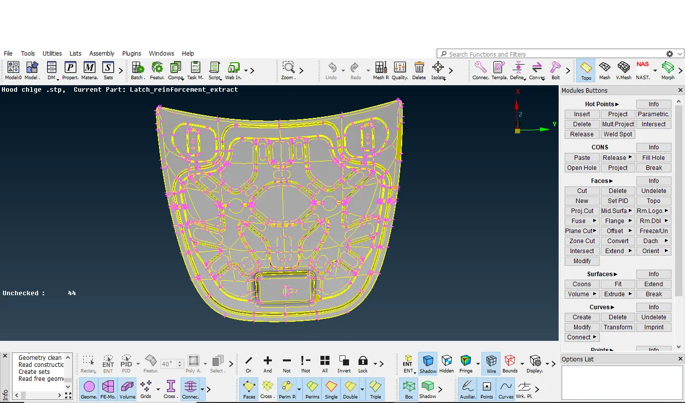
- After opening the model there are different components present in that CAD model namely outer extract, inner extract, latch reinforcement, and hinge reinforcements. All these components are separated by properties and their PID dialog box are shown below,
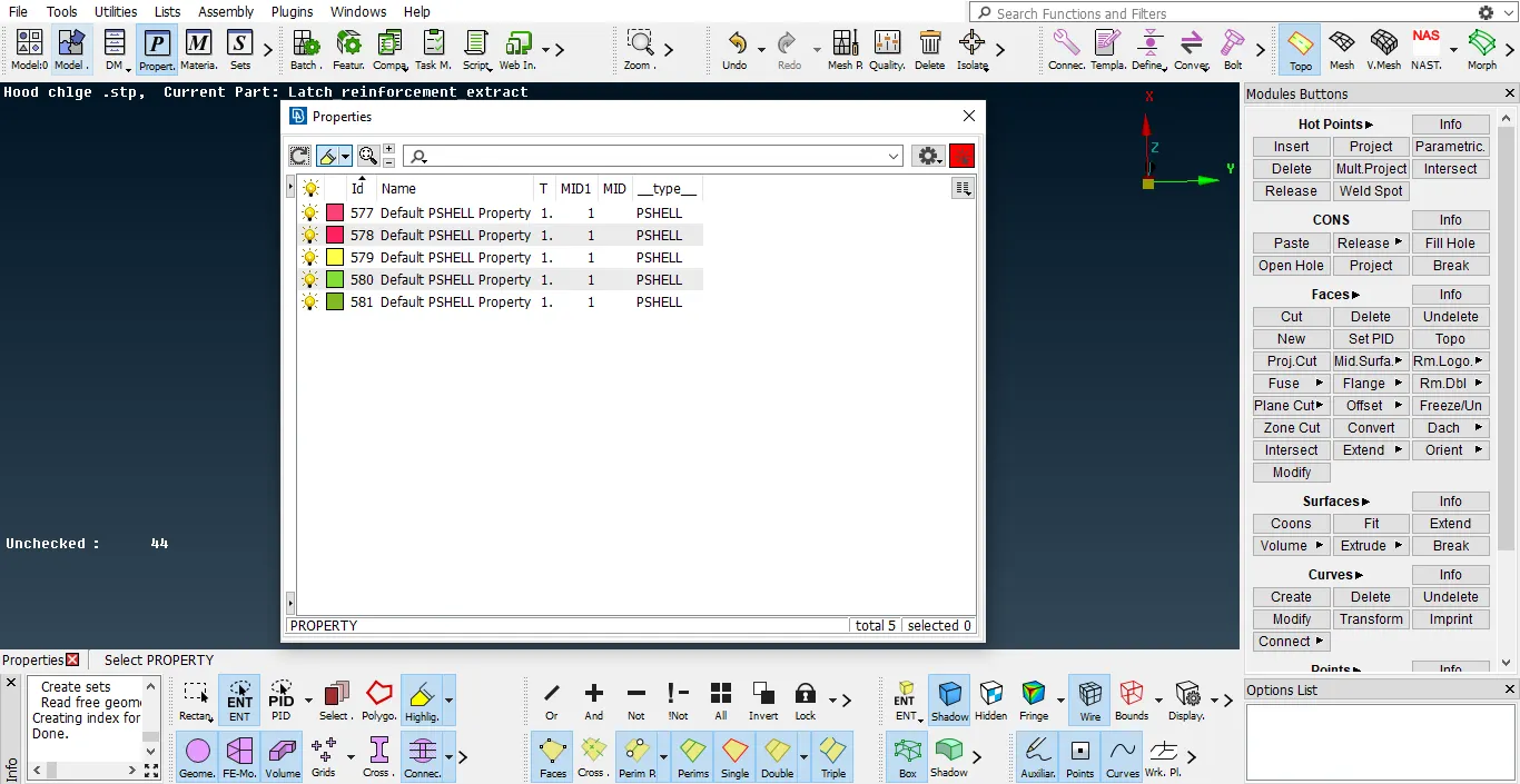
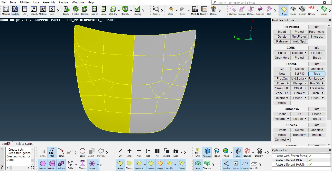
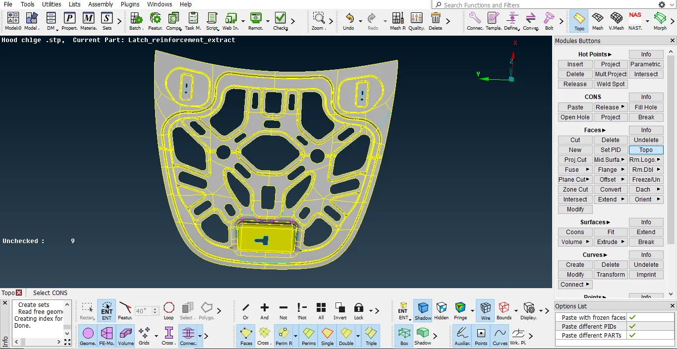
- By selecting each PID's respective components will show individually. The four different component images are shown below,
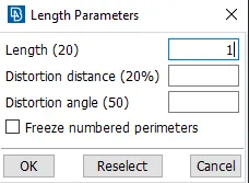
- Now go to the mesh module in the modules toolbar and select the length option under the section of the perimeters. By clicking that two options will display namely perimeters and macros, while we select the perimeters option and select the whole model, for confirmation of selection click the middle mouse button.
- By confirming it shows a dialog box. In that dialog box, the length is entered as 1 mm because we want a refined model for performing all operations properly, and these changes also used for good visualization of the model. Hence the length parameters dialog box are shown as below,
- Finally, Topo operation proceeds for the whole model by selecting the topo options which is present under faces in the topo module.
STEP-2
Geometry Cleanup:
- Now we want to check the geometrical errors in this model by selecting check ->Geometry which is present under the Tools toolbar. When we select that option a dialog box will appear in that dialog box there are so many options to check the geometry of the model. Some of the options like single cons, double cons, triple cons, cracks between cons, overlap faces, needle faces etc.
- Select the necessary options to clear the geometry cleanup process and click the execute option to check. After execution is completed if an error may present it will display in that table with a defined geometric form. Some of the errors obtain while we execute this model are shown below,
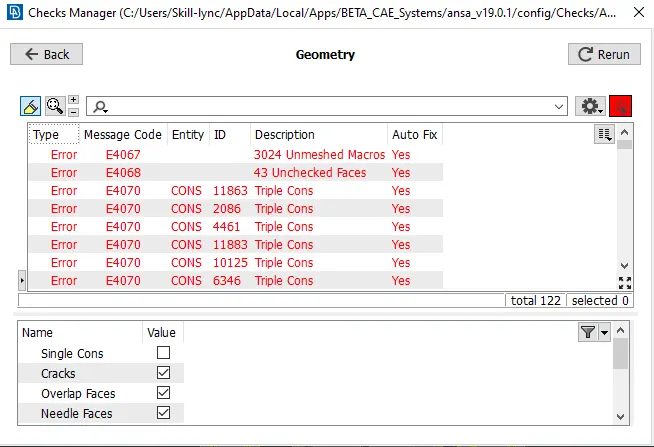
- The errors like needle faces and unchecked faces are cleared by using auto fix option that should be selected by right click that errors or selecting all the errors and right click the mouse button it will show some options in that autofix also present. Other errors like triple cons are resolved through the individual area by area. To resolve the issue of triple cons Release option in cons section is used and the Topo option in the Faces section is used to stitch the component.
- Repeat the process to check again for geometric issues by executing the check.
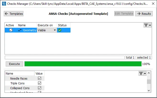
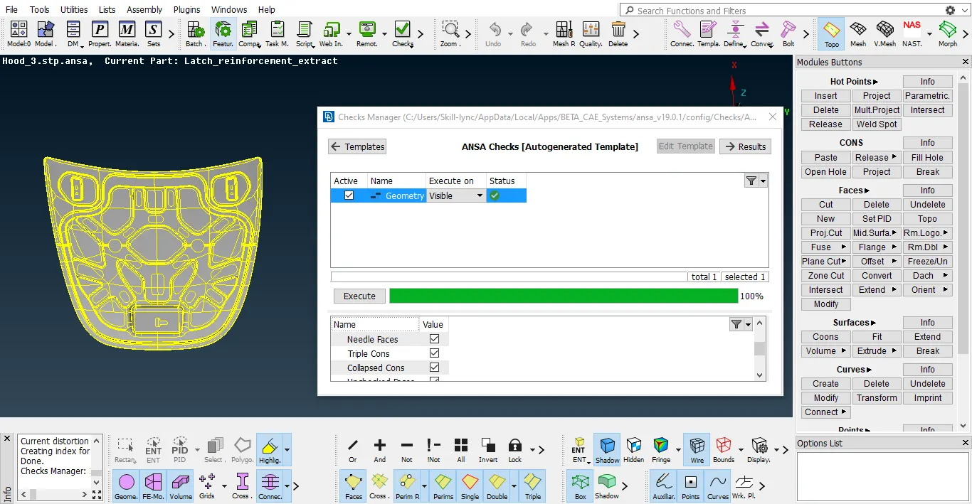
- By resolving these errors we execute the geometry clean up when all the errors are completely cleared and it will show that 100% geometry visible in that dialog box which is shown below,
- The same process will be followed for each component for geometry clean up when all the components are cleared 100% in the geometry then the model proceeds to take mid surfacing.
STEP-3
Mid surfacing:
Outer Extract Mid Surfacing:
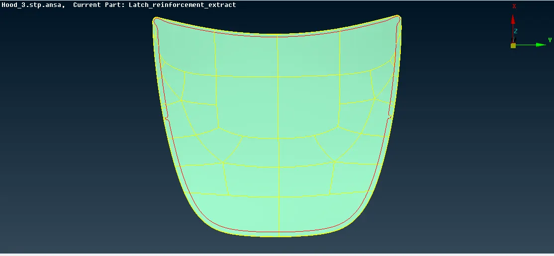
- Now store a lock view of a parent geometry to access whenever in need of it. In the outer extract, we perform mid surfacing using Auto mid or Mid surface present in the faces section of Topo module. By selecting that mid surface option a dialog box will appear to select the face. After selecting the face middle click the mouse button for confirmation then the mid surface is generated automatically.
- While we creating the mid surfacing of the component the parent geometry will be deleted in some time when using the Mid surface option. An offset option in faces under the section of Topo module is also used to create mid surface but in offset options, a dialog box will appear and in that dialog box a length of mid surface value required. An advantage of using the offset option is a parent geometry will not be deleted.
- On confirming Mid surface option we get a mid surface that is formed from the parent surface and its property ID gets created automatically. A created outer extract mid surface is shown as below,
Inner Extract Mid Surfacing:
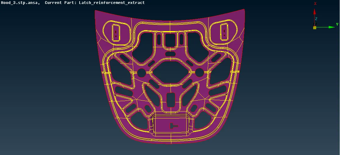
- The same process for outer extract mid surfacing should be followed in this inner extract mid surface also here we perform mid surfacing using Auto mid or Mid surface present in the faces section of the Topo module. By selecting that mid surface option a dialog box will appear to select the face. After selecting the face middle click the mouse button for confirmation then the mid surface is generated automatically.
- On confirming Mid surface option we get a mid surface that is formed from the parent surface and its property ID gets created automatically. A created inner extract mid surface is shown as below,
Latch Reinforcement Mid Surfacing:
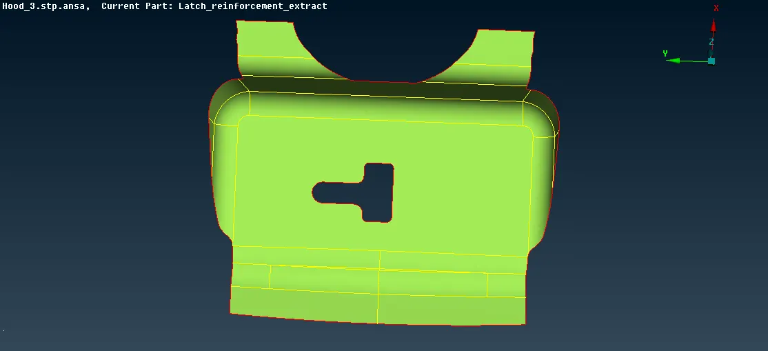
- In latch reinforcement mid surfacing we perform the manual mid surface option because this component is not much complex than the inner and outer part. Therefore offset option is used here that is present in the Faces section of the Topo module. The offset distance value is entered manually in this option and the mid surface is taken as one by one to obtain a perfect mid surface.
- While using the offset option the mid surface boundary line is selected by one by one and confirm the offset distance value and click the middle button in the mouse to execute the mid surface of that component.
- We also have to create a property ID manually in this offset option. To create the property ID go to the list toolbar and then select properties options in that properties option create the new property ID by right click and create a new property -> PSHELL hence the property ID will be created. The mid surface of latch reinforcement is shown as below,
Hinge Reinforcements Mid Surfacing:
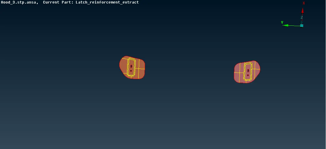
- The same process for latch reinforcement mid surfacing is followed in Hinge reinforcements also we perform the manual mid surface option because this component is not much complex than the inner and outer part. Therefore offset option is used here that is present in the Faces section of the Topo module. The offset distance value is entered manually in this option and the mid surface is taken as one by one to obtain a perfect mid surface.
- While using the offset option the mid surface boundary line is selected by one by one and confirm the offset distance value and click the middle button in the mouse to execute the mid surface of that component.
- We also have to create a property ID manually in this offset option. To create the property ID go to the list toolbar and then select properties options in that properties option create the new property ID by right click and create a new property -> PSHELL hence the property ID will be created. The mid surface of hinge reinforcements is shown as below,
- Now again check the geometry clean up after creating a mid surface but this time unselect the single cons checkbox and execute the check because surfaces formed have no sharped surfaces at their boundaries therefore they are represented by single cons.
- Geometry cleanup after the mid surface is mandatory to proceed for further process.
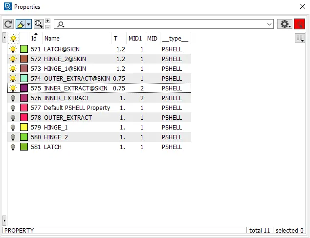
- Therefore all four components of mid surface property ID is created in that properties option present in the toolbar and that dialog box is shown below,
STEP-4
Meshing:
Meshing is an integral part of the engineering simulation process where complex geometries are divided into simple elements that can be used as discrete local approximations of the larger domain. The mesh influences the accuracy, convergence, and speed of the simulation. Furthermore, since meshing typically consumes a significant portion of the time it takes to get simulation results, the better and more automated the meshing tools, the faster and more accurate the solution.
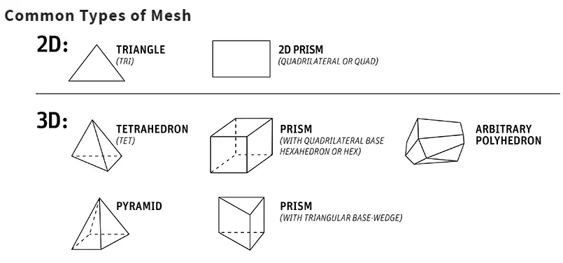
- We proceed to mesh by changing the Topo module into the mesh module in the Modules toolbar.
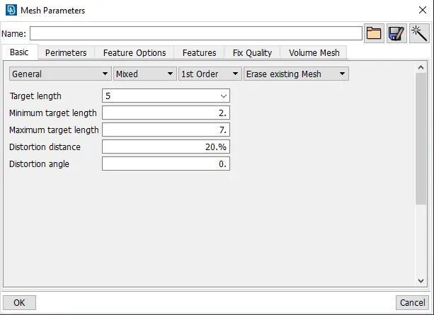
- Before entering into mesh we want to denote the average length, minimum length, and maximum length value in the mesh parameters which is present in the utilities toolbar. The value of these three lengths is given from quality criteria. The mesh parameters dialog box with the quality criteria assigned value is given below,
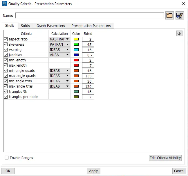
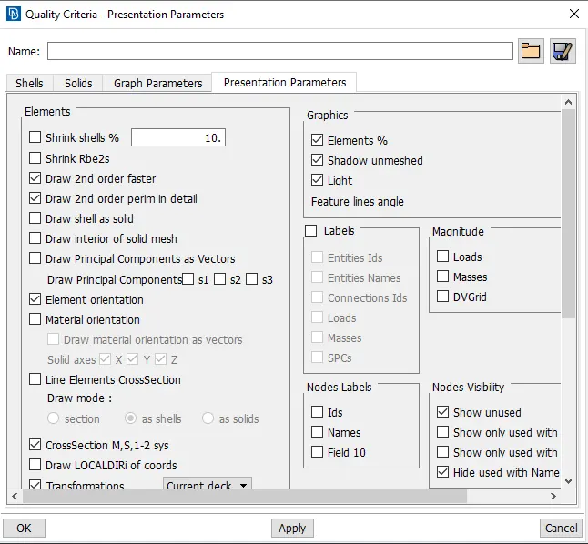
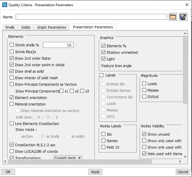
- After that, we set the quality criteria value given by the instructor to get the good quality of the mesh. To open the quality criteria dialog box press F11 button or go to the utilities toolbar and select the Quality criteria option hence the dialog box will appear. Select the quality criteria in the shell and assign the value that is given by the instructor for good mesh flow. In that same dialog box, a presentation parameter is also present to click that option and select elements % checkbox and the details on demand effect are given as all details. The dialog box for quality criteria presentation parameters and the assigned value is shown below,
Outer Extract Meshing:
- First, we want to delete the unnecessary Hot points in that model by using the Delete option in the Hot point sections. Then remove unnecessary construction lines by using Cut options in the Macros section. This two instruction is used to get the mesh flow as good quality and to reduce the trias percentage. Eliminate the unwanted construction lines which are under the length of minimum length quality criteria. In some other place if two lines are present and that lines are failed for quality criteria minimum length value then create a mid surface line in-between that two lines and eliminate that two lines hence the mid surface referred that the structural line of that component.
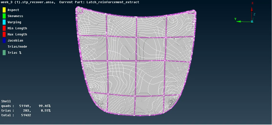
- In this below outer extract meshing, the construction line is rearranged for the purpose of obtaining a good mesh and to reduce the trias percentage. The rearrangement of the construction line in the outer extract does not affect the geometry model it is considering only mesh flow.
- Now mesh the component using the Best Mesh option in the Mesh generation section. After that, we want to select Reconstruct or Smooth option in the Shell Mesh section because of the alignment of trias or get a better arrangement of mesh flow.
- To clear the trias into quad or to align the trias in the same direction we use Split and Swap options in the Elements section. The Split option is used to move forward the tria and the Swap option is used to move the tria in the right or left side of the mesh.
- By clearing the off elements and the arrangements of trias will lead to good mesh flow. An outer extract meshed component image is shown as below,
Inner Extract Meshing:
- The Inner extract component is much complicated compared with the outer extract component so we want to delete the half of the faces because it is a symmetrical component. By deleting the half face of that component an execution of mesh should be easy and it could not affect the geometry. To delete the half face of the component using the Delete option in the faces section under the Topo module.
- After deleted the half of the face in that component we want to remove the unnecessary Hot points in that model by using the Delete option in the Hot point sections. Then remove unnecessary construction lines by using Cut options in the Macros section. This two instruction is used to get the mesh flow as good quality and to reduce the trias percentage. Eliminate the unwanted construction lines which are under the length of minimum length quality criteria. In some other place if two lines are present and that lines are failed for quality criteria minimum length value then create a mid surface line in-between that two lines and eliminate that two lines hence the mid surface referred that the structural line of that component.
- Now mesh the component using the Best Mesh option in the Mesh generation section. After that, we want to select Reconstruct or Smooth option in the Shell Mesh section because of the alignment of trias or get a better arrangement of mesh flow.
- To clear the trias into quad or to align the trias in the same direction we use Split and Swap options in the Elements section. The split option is used to move forward the tria and the Swap option is used to move the tria in the right or left side of the mesh.
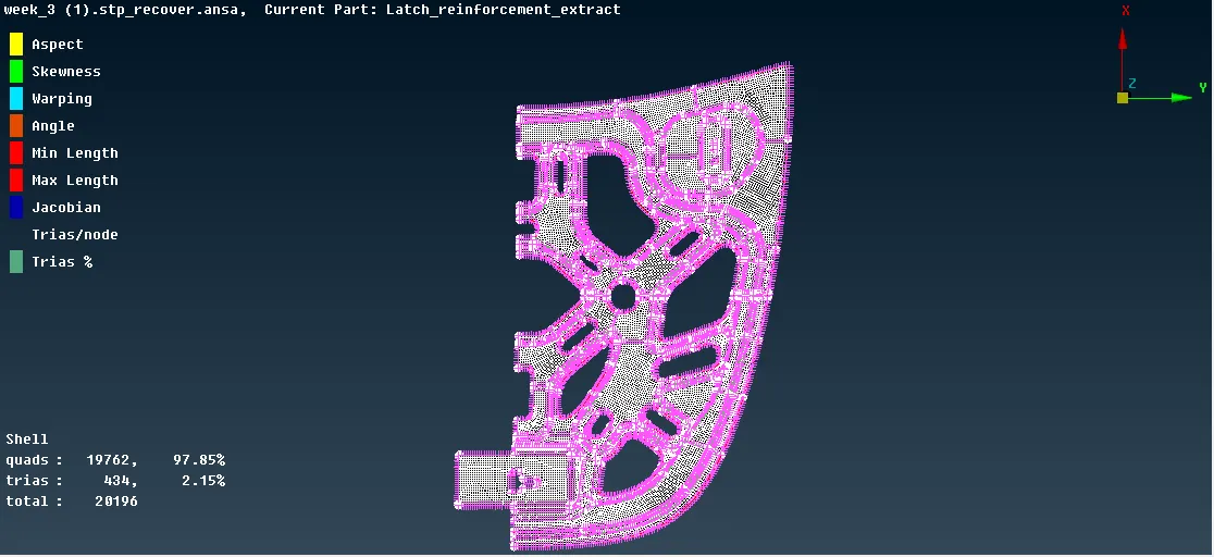
- By clearing the off elements and the arrangements of trias will lead to good mesh flow. The half face of the inner extract meshed component image is shown below,
- Now copy the inner extract half face mesh to the symmetrical side for complete the meshing process in that component by selecting the Transform option in that Utilities toolbar. After selecting the transform option the two options will be displayed they are copy and move. Select the copy option then a dialog box will appear in that dialog box select Entities option and confirm the model that you want to symmetry then press the middle mouse button to for confirmation.
- After confirmation of that symmetry model Copy Entities dialog box will appear in that box go to the symmetry section you can see the option Default Symmetry plane that image is shown below,
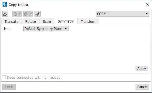
- In that symmetry, section to change the option as Mirror 3 points plane and mention the three points in the half face of inner extract and click apply to get symmetry part. Finally select the Finish option to get the symmetry part of that component.
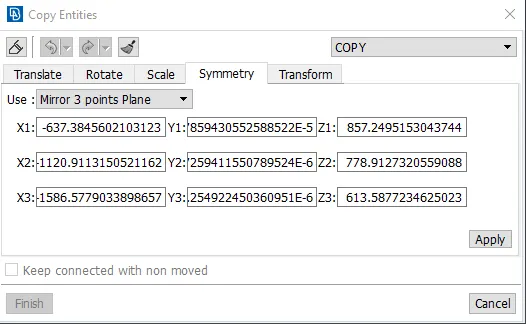
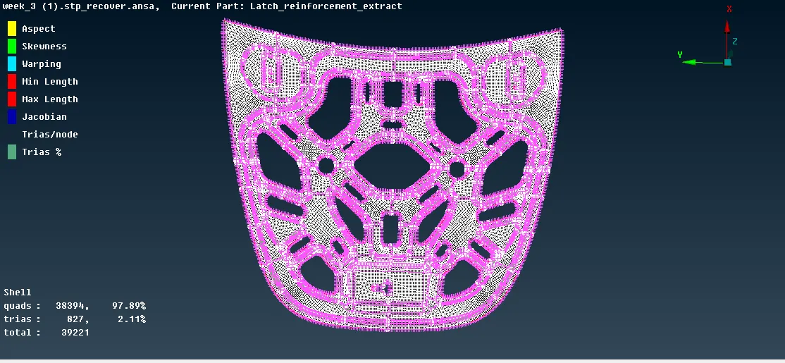
- Now we obtain the total mesh of the inner extract component verify any opposite trias are present after the symmetry condition and clear that opposite trais into quads.
- In this below inner extract meshing, the construction line is rearranged for the purpose of obtaining a good mesh and to reduce the trias percentage. The rearrangement of the construction line in the inner extract does not affect the geometry model it is considering only mesh flow.
Latch Reinforcement Meshing:
- First we want to remove the unnecessary Hot points in that model by using the Delete option in the Hot point sections.
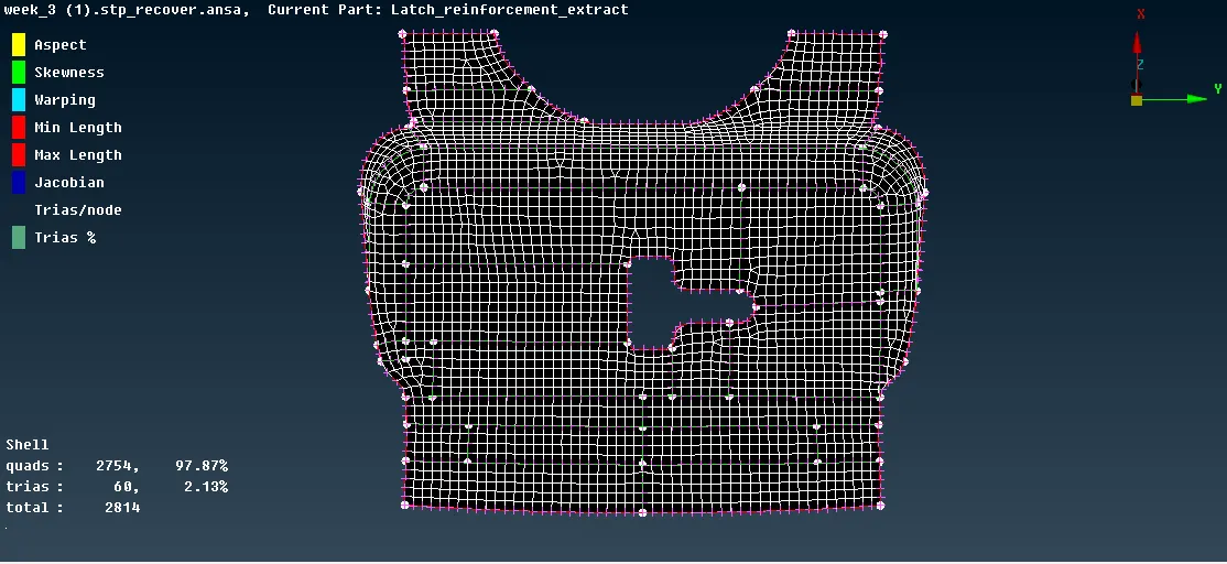
- In latch reinforcement meshing, only some construction line is rearranged for the purpose of obtaining a good mesh and to reduce the trias percentage. The rearrangement of the construction line in this model does not affect the geometry model it is considering only mesh flow.
- Now mesh the component using the Best Mesh option in the Mesh generation section. After that, we want to select Reconstruct or Smooth option in the Shell Mesh section because of the alignment of trias or get a better arrangement of mesh flow.
- To clear the trias into quad or to align the trias in the same direction we use Split and Swap options in the Elements section. The split option is used to move forward the tria and the Swap option is used to move the tria in the right or left side of the mesh.
- By clearing the off elements and the arrangements of trias will lead to good mesh flow. A latch reinforcement meshed component image is shown below,
Hinge Reinforcements Meshing:
- The same meshing steps for the other three components are followed in this Hinge reinforcements also. At first, we want to remove the unnecessary Hot points in that model by using the Delete option in the Hot point sections then remove unnecessary construction lines by using the Cut options in the Macros section.
- After that mesh the component using the Best Mesh option in the Mesh generation section. To align the trais, we want to select Reconstruct or Smooth option in the Shell Mesh section because of the alignment of trias or get a better arrangement of mesh flow.
- To clear the trias into quad or to align the trias in the same direction we use Split and Swap options in the Elements section. The split option is used to move forward the tria and the Swap option is used to move the tria in the right or left side of the mesh.
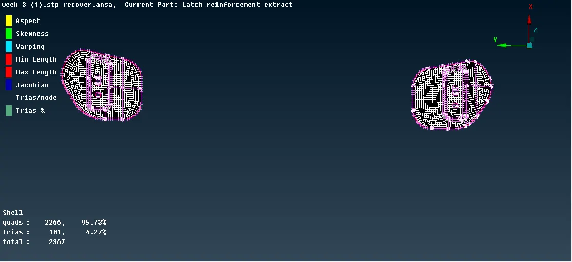
- By clearing the off elements and the arrangements of trias will lead to good mesh flow. The hinge reinforcements meshed component image is shown as below,
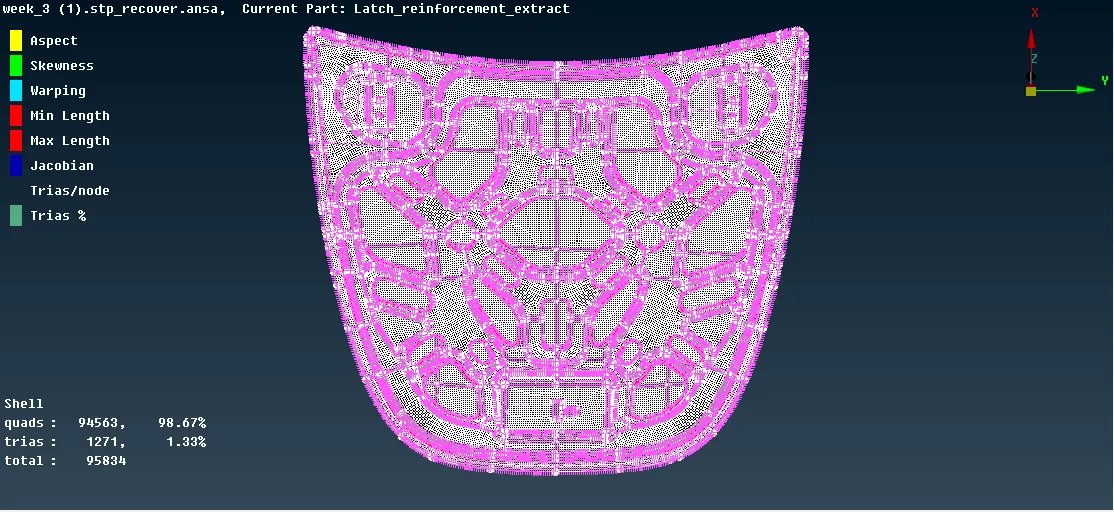
- We finally obtain a good mesh of about 98.67% of quad elements and 1.33% of tria elements which the tria element percentage in our model is less than the target given in quality criteria by the instructor. The total meshed model and the element shell detail image is shown below,
- Now we have to assign the thickness to the meshed component by selecting the Utilities toolbar and click the Quality Criteria option or press F11 key to open the quality criteria dialog box. In that dialog box select, the presentation parameters section click the draw shell as solid checkbox now the thickness is assigned in that model. The quality criteria dialog box with a selection of draw shell as solid checkbox are shown as below,
CONCLUSION:
The results show that the mesh was completed in this model by clearing the geometry errors and by creating the mid surface in both manual and auto mid options. The total element present in that model, trias percentage, and the quad percentage details will be available by enable the element % option and select all details options in the quality criteria under the presentation parameter. In our model, we obtain 98.67% of quad elements and 1.33% of tria elements. Finally, the thickness value should be assigned using draw shell as solid option in the quality criteria dialog box under the presentation parameter section.
MODEL LINK:
https://drive.google.com/file/d/1d3nhSpD2jPQ3A4qAo7FGunT3kDOzDU3v/view?usp=sharing