Week-6 Challenge: EV Drivetrain
OBJECTIVE:
- To explain the types of power converter circuits that are employed in electric and hybrid electric vehicle.
- To solve the problem by data's that are given in the question and determine what is EV steady state speed if duty cycle is 70%
- To explain Induction Versus DC brushless motors by Wally Rippel, Tesla.
DEFINITION:
1. Types of power converter circuits employed in electric and hybrid electric vehicle
Introduction to Power Electronic Converters
The main aim of the converter is to produce conditioning power with respect to a certain application.
figure. Power Electronic Converters
The block diagram of a power electronic converter is shown in figure above. It consist of an electrical energy source, power electronic circuit, a control circuit and an electric load. This converter changes one form of electrical energy to other form of electrical energy.
Power electronic converters perform various basic power conversion functions. This converter is a single power conversion stage that can perform any of the functions in AC and DC power conversion systems.
Depending on the type of function performed, power electronic converters are categorized into following types.
- AC to DC= Rectifier: It converts AC to unipolar (DC) current
- DC to AC= Inverter: It converts DC to AC of desired frequency and voltage
- DC to DC= Chopper: It converts constant to variable DC or variable DC to constant DC
- AC to AC= Cycloconverter, Matrix converter: It converts AC of desired frequency and/or desired voltage magnitude from a line AC supply.
AC to DC Converters or Rectifiers
An AC to DC converter is also called a rectifier, which converts AC supply from main lines to DC supply for the load. The block diagram of an AC to DC converter is shown in figure below.
DC to AC Converters or Inverters
These converters are connected between DC source of fixed input, and variable AC load. Most commonly, these DC to AC converters are called as inverters. An inverter is a static device that converts fixed DC supply voltage to variable AC voltage.
Here the fixed DC voltage is obtained from batteries or by DC link in most power electronic converter. The output of the inverter can be variable/ fixed AC voltage with variable/fixed frequency.
This conversion from DC to AC along with variable supply is produced by varying the triggering angle to the thyristors. Most of the thyristors used in inverters are employed with forced commutation technique.
These can be single phase or three phase inverter depending on the supply voltage. These converters are mainly divided into two groups. One is PWM based inverters and other multilevel inverters.
DC/DC converters for electric vehicles
The different configurations of EV power supply show that at least one DC/DC converter is necessary to interface the FC, the Battery or the Supercapacitors module to the DC-link.
In electric engineering, a DC to DC converter is a category of power converters and it is an electric circuit which converts a source of direct current (DC) from one voltage level to another, by storing the input energy temporarily and then releasing that energy to the output at a different voltage. The storage may be in either magnetic field storage components (inductors, transformers) or electric field storage components (capacitors).
DC/DC converters can be designed to transfer power in only one direction, from the input to the output. However, almost all DC/DC converter topologies can be made bi-directional. A bi-directional converter can move power in either direction, which is useful in applications requiring regenerative braking.
- Non-isolated converters
The non-isolated converters type is generally used where the voltage needs to be stepped up or down by a relatively small ratio (less than 4:1). And when there is no problem with the output and input having no dielectric isolation. There are five main types of converter in this non-isolated group, usually called the buck, boost, buck-boost, Cuk and charge-pump converters. The buck converter is used for voltage step-down, while the boost converter is used for voltage step-up. The buck-boost and Cuk converters can be used for either step-down or step-up. The charge-pump converter is used for either voltage step-up or voltage inversion, but only in relatively low power applications.
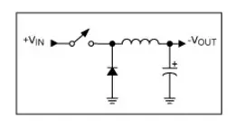
(a) Step-Down (Buck) Converter
A step-down circuit is used to generate a lower voltage than the input. It is also called a buck. The polarities are the same as in the input.
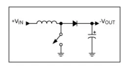
(b) Step-Up (Boost) Converter
A step-up circuit is used to generate a higher voltage than the input voltage. It is called as a boost. The polarities are same as in the input.
(c) Buck-Boost Converter
In Buck-Boost converter, the output voltage can be increased or decreased than the input voltage. It works to either boosting or bucking the voltage. The common usage of this converter is to reverse the polarity.
(d) Cuk: This type of converter is similar to the Buck-Boost converter. The difference is its name, named after Slobodan Cuk, the man who created it.
(e) Charge Pump: This converter is used to step the voltage up or down in applications that have low power.
- Isolated converters
Usually, in this type of converters a high frequency transformer is used. In the applications where the output needs to be completely isolated from the input, an isolated converter is necessary. There are many types of converters in this group such as Half-Bridge, Full-Bridge, Fly-back, Forward and Push-Pull DC/DC converters (Garcia et al., 2005), (Cacciato et al., 2004). All of these converters can be used as bi-directional converters and the ratio of stepping down or stepping up the voltage is high. Some of the types are explained below,
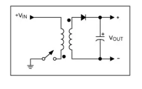
(a) Flyback converter
This converter works similar to the buck-boost converter of the non-isolating category. The difference is it uses a transformer to store energy instead of an inductor.
(b) Forward Converter
This converter will use the transformer to send the energy, between the input and output in a single step.
AC to AC Converters
AC/AC converters connect an AC source to AC loads by controlling amount of power supplied to the load. This converter converts the AC voltage at one level to the other by varying its magnitude as well as frequency of the supply voltage.
These are used in different types of applications including uninterrupted power supplies, high power AC to AC transmission, adjustable speed drives, renewable energy conversion systems and aircraft converter systems.
2. To solve the problem by data's are given in the question and determine What is EV steady state speed if duty cycle is 70% ?
Given Data,
Mass(m) = 1000kg
Drag Coefficient (Cd) = 0.2
Frontal Area(A) = 2 sq-m
Coefficient of Rolling Resistance (c_o)=0.009
Gear Ratio C1 = 1
Density (ρ) = 1.1614 kg/cub-mtr
Radius of the wheel (r) = 11 inches
= 0.28 m
Rated Armature Voltage (V) = 72 V
Rated Armature current (I) = 400 A
Armature Resistance Ra = 0.5Ω
Armature Inductance La = 8 mH
Motor Constant Kφ = 0.7 V-s
Chopper Switching frequency = 400 Hz
Duty Cycle = 70%
TO FIND:
What is EV steady state speed if duty cycle is 70% ?
FORMULA USED:
The Rolling Resistance Force
Frr = `mu`rr.m.g
Drag Force
Fad = 0.5.ρ.A.v^2.Cd
The Total Tractive Force
Fte = Frr + Fad
Speed-Torque Equation for D.C Motor
ω = (V/kφ)-(T.R/(kφ)^2)
SOLUTION:
We find the Rolling Resistance Force
Frr = `mu`rr.m.g
Frr = 0.009*1000*9.81
Frr = 88.29 N
Then we find the Drag Force
Fad = 0.5.ρ.A.v^2.Cd
Fad = 0.5*1.1614*2*v^2*0.2
Fad = 0.232*v^2
Fad = 0.232*ω^2*(0.28)^2
Fad = 0.01821*ω^2
The Total Tractive Force
Fte = Frr + Fad
Fte = 88.29+(0.01821*ω^2)…………….(Equation-1)
We know that
Fte =G.T/r
Substituting in (1)
(1*T)/0.28 = 88.29+(0.01821*ω^2)
T_TR = 24.72+0.0051*ω^2………….(Equation-2)
The vehicle characteristics are given by the equation(2) and it's derived
TTR=24.7+0.0051w2
Which is given in the question
We know that
Speed-Torque Equation for D.C Motor
ω = (V/kφ)-(T.R/(kφ)^2)
By rearranging it in form torque equation
T = ((V.kφ)/R)-(ω.(kφ)^2/R)
Substituting the values of voltage ,kphi, Armature Resistance, we get
Before that,
In the question, it given that the duty cycle is 70%
Therefore we need the find out the voltage at 70% duty cycle
V = 72*0.7 = 50.4V
T = ((50.4*0.7)/0.5)-((ω.(0.7)^2)/0.5)
T_m = 70.56-(ω*0.98)…………Equation (3)
At the steady state condition of EV
T_TR = Tm
Now substituting the values of T_TR and Tm i.e equation (2) and (3)
24.72+0.0051*ω^2 = 70.56-(ω*0.98)
(0.0051*ω^2) + (ω*0.98)-45.84 = 0
Omega value will always be positive therefore
ω = 38.90 rad/sec
RESULT:
EV steady state speed if duty cycle is 70% is, ω = 38.90 rad/sec
3. Induction Versus DC brushless motors by Wally Rippel, Tesla
DC brushless drives:
- In brushless machines, the rotor includes two or more permanent magnets that generate a DC magnetic field (as seen from the vantage point of the rotor). In turn, this magnetic field enters the stator core (a core made up of thin, stacked laminations) and interacts with currents flowing within the windings to produce a torque interaction between the rotor and stator. As the rotor rotates, it is necessary that the magnitude and polarity of the stator currents be continuously varied – and in just the right way - such that the torque remains constant and the conversion of electrical to mechanical energy is optimally efficient.
- The device that provides this current control is called an inverter. Without it, brushless motors are useless motors.
- A brushless DC motor produces no starting torque when directly connected to fixed frequency utility power. They really need the aid of an inverter whose “phase” is maintained in step with the angular position of the rotor.
- One of the main differences is that much less rotor heat is generated with the DC brushless drive.
- Rotor cooling is easier and peak point efficiency is generally higher for this drive.
- In an ideal brushless drive, the strength of the magnetic field produced by the permanent magnets would be adjustable.
- DC brushless drives require an absolute position sensor.
Induction motor drives:
- The induction rotor has no magnets – just stacked steel laminations with buried peripheral conductors that form a “shorted structure.” Currents flowing in the stator windings produce a rotating magnetic field that enters the rotor.
- In turn, the frequency of this magnetic field as “seen” by the rotor is equal to the difference between the applied electrical frequency and the rotational “frequency” of the rotor itself. Accordingly, an induced voltage exists across the shorted structure that is proportionate to this speed difference between the rotor and electrical frequency. In response to this voltage, currents are produced within the rotor conductors that are approximately proportionate to the voltage, hence the speed difference. Finally, these currents interact with the original magnetic field to produce forces – a component of which is the desired rotor torque.
- The fact that induction motors are directly compatible with conventional utility power is the main reason for their success.
- When a 3-phase induction motor is connected to utility type 3-phase power, torque is produced at the outset. the motor has the ability to start under load. No inverter is needed.
- In contrast, induction machines have no magnets and B fields are adjustable.
- Induction drives require only a speed sensor.
Similarities of Induction And DC brushless derives:
- Both DC brushless and induction drives use motors having similar stators.
- Both drives use 3-phase modulating inverters. The only differences are the rotors and the inverter controls. And with digital controllers, the only control differences are with control code.
CONCLUSION:
We conclude that DC brushless drives will likely continue to dominate in the hybrid and coming plug-in hybrid markets, and that induction drives will likely maintain dominance for the high-performance pure electrics.
The fact that so much of the hardware is common for both drives could mean that we will see induction and DC brushless live and work side by side during the coming golden era of hybrid and electric vehicles.