Meshing the Hood model using HYPERMESH
AIM:
- To check for the geometrical errors for the given component.
- To extract all the mid surfaces of the given component with a suitable method.
- To mesh all components in the model with the given element Quality criteria.
OBJECTIVE:
- To write a detailed report on the meshing process and also mention which method we used to extract the mid-surface.
QUALITY CRITERIA:
Mesh all the components in the given model by using the following quality criteria of target Element Length = 5mm
| S.N | Quality Criteria | Value |
| 1 | Aspect Ratio | 5 |
| 2 | Skewness | 45 |
| 3 | Warping | 15 |
| 4 | Taper | 0.5 |
| 5 | Min. Length | 2mm |
| 6 | Max. Length | 8mm |
| 7 | Min angle Quad | 45 |
| 8 | Max angle Quad | 135 |
| 9 | Min angle Tria | 20 |
| 10 | Max angle Tria | 120 |
| 10 | Tria % | 10 |
1. Target element length:
It is the size of the element by which we can get the most nearer approximate value of the result compared to the experimental result.
2. Minimum element length:
The minimum element length is given by the instructor for the reason of quality criteria to avoid the presence of any zero-length element. It is very important to check for crash analysis.
3. Aspect ratio:
The aspect ratio is defined as the ratio of max element edge length to the minimum element edge length. The ideal value for aspect ratio is 1 but less than 5 is acceptable.
4. Wrap angle:
Wrap angle is defined as the angle between normal of the two planes by splitting the quad elements along the diagonal. Therefore the maximum angle allowed between the two possibilities is called the wrap angle. The ideal value is 0 degree but less than 10 degree is acceptable for good practices.
The wrap is not applicable in the triangular element.
5. Skewness:
If the quad element is not square and has deformation then the skewness defined as the minimum angle between the two lines joining the opposite mid sides of the element similarly for the triangular element it is 90 minus between the line from each node to the opposing mid-side. The ideal value is 0 but less than 45 degree is acceptable
6. Jacobian:
Jacobian is the scale factor used in the transformation of a co-ordinated system. This is used for a faster analysis point of view. The ideal value is 1 but greater than 0.6 is acceptable.
It is global to the local coordinate system.
PROCEDURE:
IMPORTING THE MODEL:
- First, we want to import the model using the import option and select the file type as STEP and open the model from the browser tab and select the file as Hood. stp and click the import option to get the model in the graphical area the selection process is shown below,
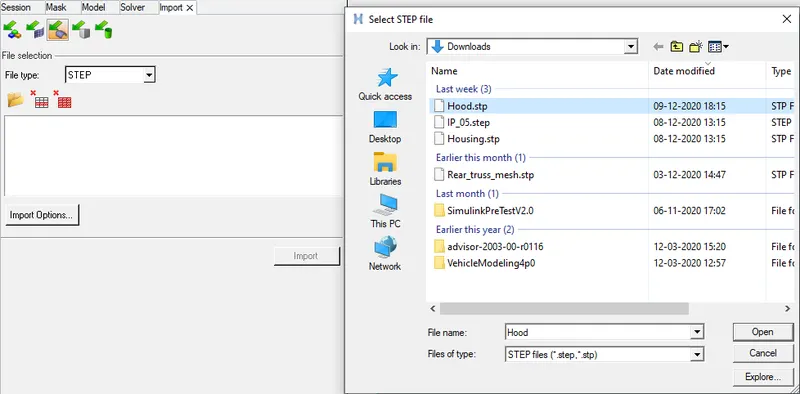
Fig: Import selection
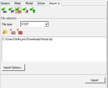
Fig: Import model
- After importing the file an open model will appear in the graphical area in this model there are different components present in that CAD model namely outer extract, inner extract, latch reinforcement, and hinge reinforcements. All these components are separated by properties and their component name and that is below,
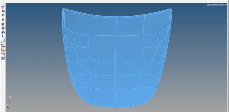
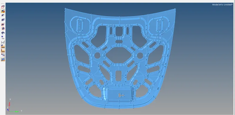
Fig: Outer and Inner extract open model
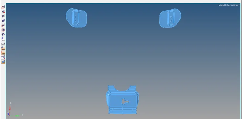
Fig: Latch and hinge reinforcement open model
- Then delete the solid surface in that model by selecting Delete> to select the surface and click delete entity hence the solid surface is deleted and that is shown as below,
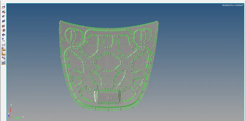
Fig: Hood model with deleted solid surface
- Now create a mid surface for this model by selecting the Geom>mid surface and select the extraction option as skin offset. Here we using the skin offset in the extraction option because the skin offset will give a better mid surface in the region of a fillet, hence the selection process is shown below,

Fig: Extraction options
- After selecting the extraction options click the auto extraction and select the model with surface and click extract to obtain the mid surface for that model. The mid surface selection process is shown below,

Fig: Midsurface option
- Now the mid surface for hood components is obtained and they are kept in individual components properties that will make to separate the mid surface with parent geometry. Therefore the mid surface for all the five components are obtained and they are shown as below,
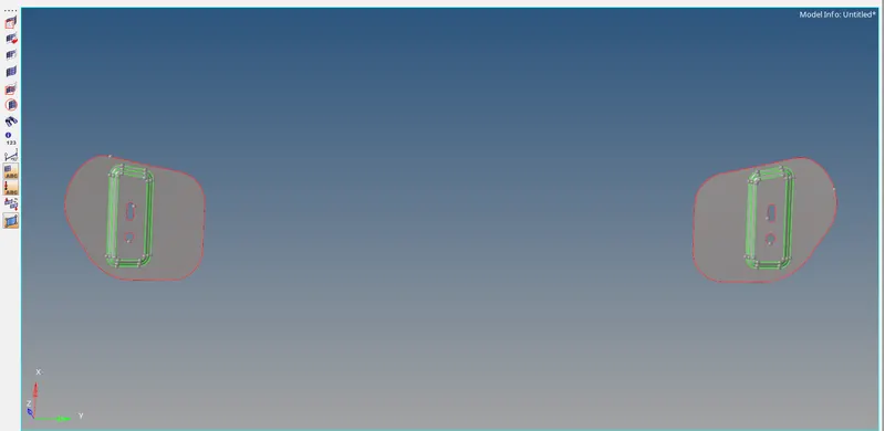
Fig: Hinge reinforcement mid surface
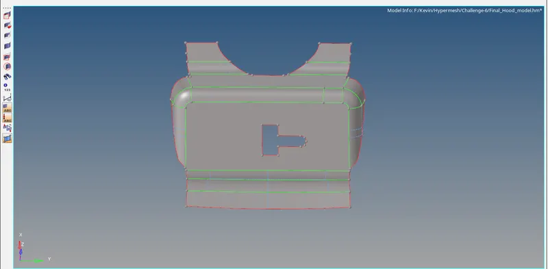
Fig: Latch reinforcement mid surface
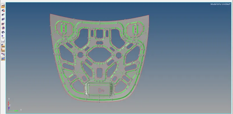
Fig: Inner extract body mid surface
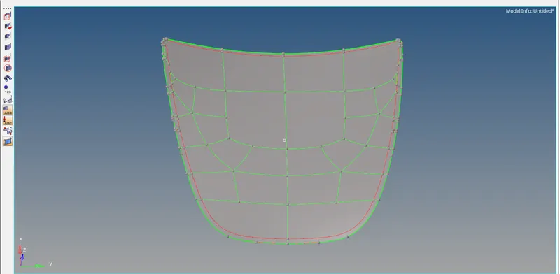
Fig: Outer extract body mid surface
GEOMETRY CLEANUP:
- Now we want to clean up the geometry in the mid-surface component because of the meshing process. While we doing the meshing operation the quality criteria may be affected due to the unwanted lines in the mid surface that line may below the value of minimum element size so that we are toggling that line to obtain a good mesh flow. The quality will be cleared when we toggling the line.
- Splitting is the method to get the good mesh flow in the non-planner region and other shape regions like a circle, hexagonal and oval, etc. here we splitting the region into two surfaces to get the good mesh flow by selecting the spilt surf node option and select the node or line to split in that region. The selection process is shown below,

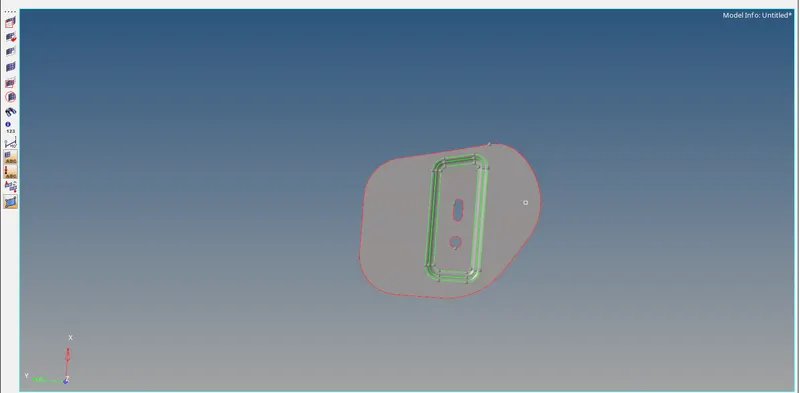
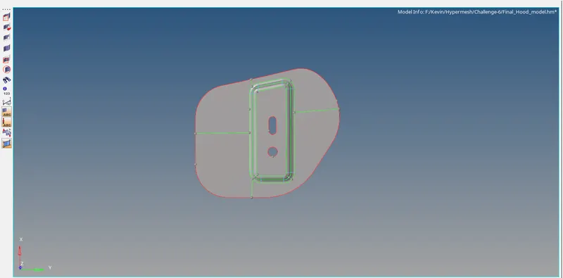
Fig: Hinge reinforcement geometry clean up
- Now we want to clean up the geometry in the mid-surface component because of the meshing process. While we doing the meshing operation the quality criteria may be affected due to the unwanted lines in the mid surface that line may below the value of minimum element size so that we are toggling that line to obtain a good mesh flow. The quality will be cleared when we toggling the line.
- A toggle option is also used to toggle the line while the clean up in geometry and the selection process is shown below,

Fig: Toggle option
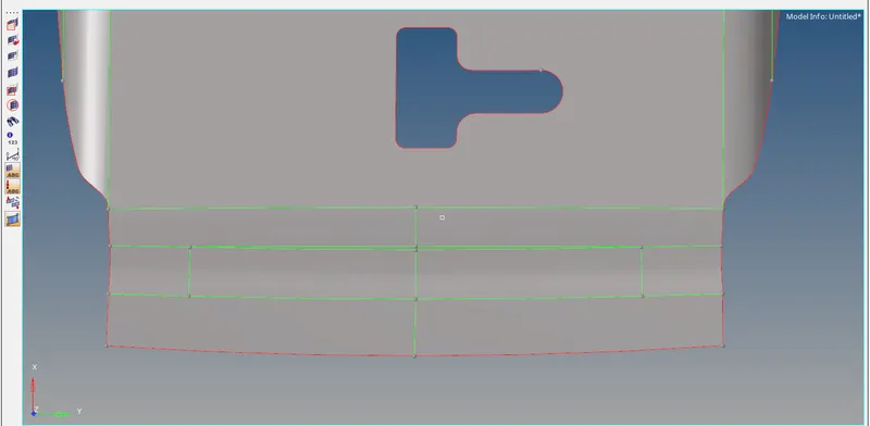
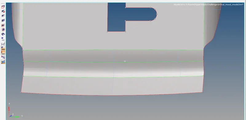
Fig: Latch reinforcement geometry clean up
- To get a good mesh flow in the fillet region of the inner extract body is toggle the line or create a line in the middle area of the part and spilt the surfaces as two regions. Remove the unwanted lines that could be below the minimum element size value. Here the created line in the inner extract body is shown as below,
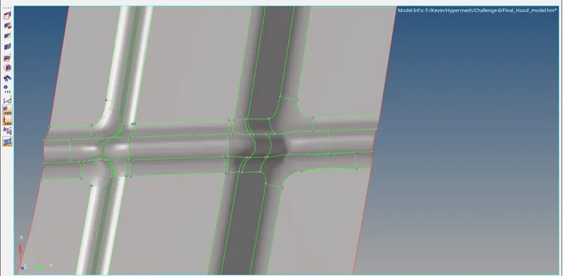
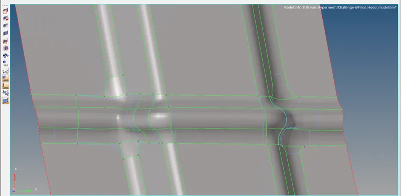
Fig: Inner extract body geometry clean up
- The lines can arrange with the own ideology that may not affect any mesh and geometry in that model. Toggle the irregular shaped line and to create the new lines in the regular shape and that will keep the mesh as good flow. The outer extract is arranged as a rectangular form to avoid the trais as a maximum level. The created lines for outer extract is shown below,
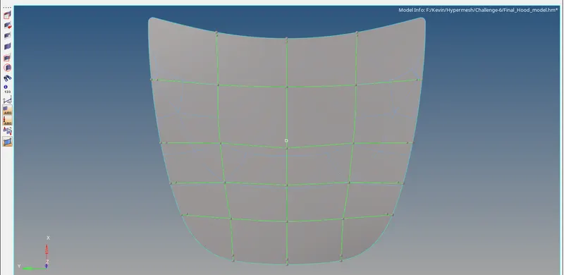
Fig: Outer extract geometry clean up
Meshing:
Meshing is an integral part of the engineering simulation process where complex geometries are divided into simple elements that can be used as discrete local approximations of the larger domain. The mesh influences the accuracy, convergence, and speed of the simulation. Furthermore, since meshing typically consumes a significant portion of the time it takes to get simulation results, the better and more automated the meshing tools, the faster and more accurate the solution.
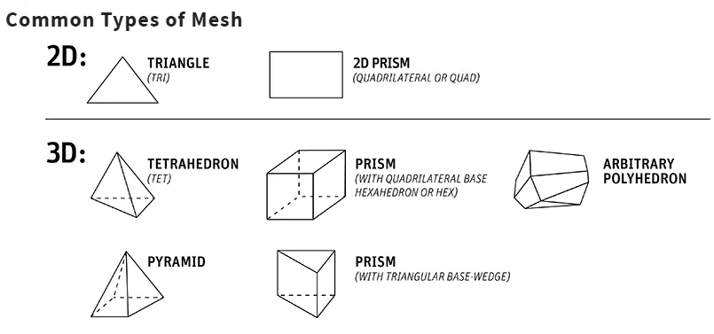
- Now create the mesh for a hood model of five components one by one by selecting 2D>automesh>enter element size as 5mm and select the surface to create mesh on that surface. Before that we want to initiate the quality criteria values in the criteria file setting that value will appear in the quality index and shows the element below or above the quality value.
- By selecting the preference >file criteria setting> and enter the quality criteria values that are given by an instructor. The quality criteria values are shown below,
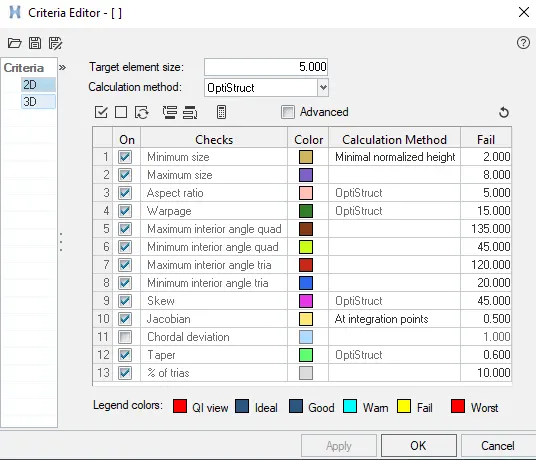
Fig: Criteria editor
- To create the mesh for an individual component by selecting 2D>automesh>enter element size as 5mm and select the surface to create mesh on that mid surface of the component. The trais will be eliminated by clean up tools in the quality index. The tools are place node, smooth, drag trias, node optimizes, element optimize, split quad element, and combine tria element, etc. These options is used to remove, drag, combine the trais, and also used to clear the quality criteria. A meshed latch surface is shown below,
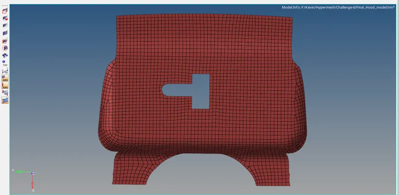
Fig: Latch reinforcement
- To move the opposite trias by using drag option in cleanup tools, opposite trias is not allowed during the meshing process, split and swap option also used to move the trias forward and backward direction. A meshed hinge is shown below,
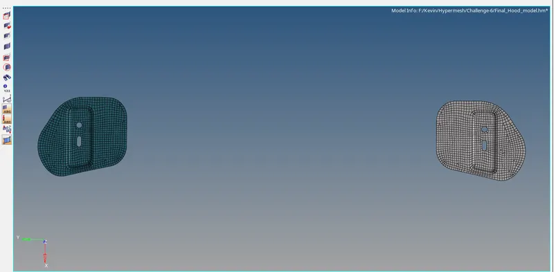
Fig: Hinge reinforcement
- To create the mesh for an individual component by selecting 2D>automesh>enter element size as 5mm and select the surface to create mesh on that mid surface of the component. The trais will be eliminated by clean up tools in the quality index. The tools are place node, smooth, drag trias, node optimizes, element optimize, split quad element, and combine tria element, etc. These options are used to remove, drag, combine the trais, and also used to clear the quality criteria.
- Check the connectivity of the mesh by selecting tool>edges>select the entire component to verify the connectivity of that mesh and click find edges option now the free edges and non-connected areas should be shown we can rectify that by giving the tolerance of connectivity as 1mm and select the component again to connect the mesh flow click preview equivalence>equivalence now the mesh will be connected.
- The connectivity also may be done manually using the replace option.
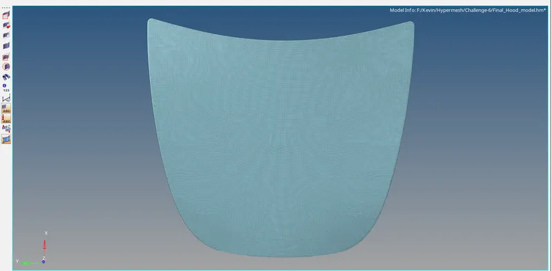
Fig: Outer extract body
- Same procedures have to be followed for the inner part also for the meshing process. The trias should be removed by drag option in cleanup tools the rebuild option is used to rearrange the mesh that may be used only for certain area to get good flow of mesh. The smooth option in 2D is also used to smooth the mesh and arrange it in a proper manner. The meshed inner extract is shown below,
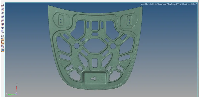
Fig: Inner extract body
- All the five individual components and their mid surface created properties are shown below,
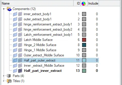
Fig: Components table
- The meshing process for all the components has done and finally thickness are assigned as per the parent geometry they are shown below,
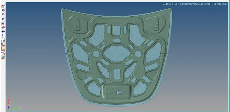
Fig: Meshed hood
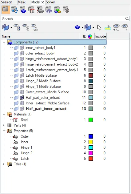
Fig: Properties
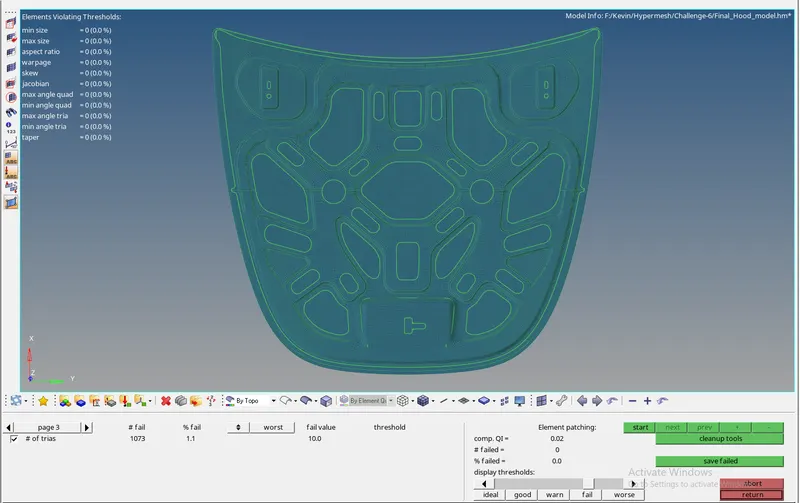
- The number of element failed for the quality criteria is 0 this shows that there is no element failure has occurred under the quality criteria and 0% element failure is obtained through our mesh they are shown below,
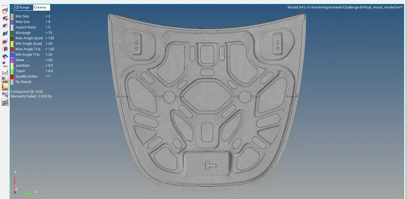
Fig: Element Quality
CONCLUSION:
Therefore we meshed all the components in the hood with individual mid-surface and the quality obtained with failure of elements. The trias percentage we obtained in the overall model is 1.1% and it is below the quality criteria value.