COMPARISON BETWEEN H-BRIDGE AND FOUR QUADRANT CHOPPER
AIM:
To study MATLAB demo ‘Speed control of a DC motor using BJT H-bridge’ and it with ‘The Four-Quadrant Chopper DC Drive (DC7) block’.
OBJECTIVE:
- To run MATLAB demo ‘Speed control of a DC motor using BJT H-bridge’ and modify the model such that armature current doesn’t shoot up when motor changes direction from forward to reverse.
- To refer help section of The Four-Quadrant Chopper DC Drive (DC7) block and compare it with H-bridge model.
- To make a suitable EV model using DC7 block and make the result report.
SOFTWARE USED: Matlab, Simulink
STUDY-1:
DEFINITION:
Insulated-Gate Bipolar Transistor:
- An insulated-gate bipolar transistor (IGBT) is a three-terminal power semiconductor device primarily used as an electronic switch which, as it was developed, came to combine high efficiency and fast switching. It consists of four alternating layers (P-N-P-N) that are controlled by a metal-oxide semiconductor (MOS) gate structure without regenerative action. Although the structure of the IGBT is topologically the same as a thyristor with a 'MOS' gate (MOS gate thyristor), the thyristor action is completely suppressed and only the transistor action is permitted in the entire device operation range.
- It is used in switching power supplies in high-power applications: variable frequency drives (VFDs), electric car, trains, variable speed refrigerators, lamp ballasts, arc-welding machines, and air conditioners.
- The IGBT is the second most widely used power transistor, after the power MOSFET.
Applications:
The IGBT is widely used in consumer electronics, industrial technology, the energy sector, aerospace electronic devices, and transportation.
Advantages:
- The IGBT combines the simple gate-drive characteristics of power MOSFETs with the high-current and low-saturation-voltage capability of bipolar transistors
- The IGBT combines an isolated-gate FET for the control input and a bipolar power transistor as a switch in a single device.
- The IGBT is used in medium- to high-power applications like switched-mode power supplies, traction motor control and induction heating.
Bridge Motor Driver Using Bipolar Transistors:
An H-bridge is an arrangement of transistors that allows a circuit full control over a standard electric DC motor. That is, an H-bridge allows a microcontroller, logic chip, or remote control to electronically command the motor to go forward, reverse, brake, and coast.
DC Motor:
- A DC motor is any of a class of rotary electrical motors that converts direct current electrical energy into mechanical energy. The most common types rely on the forces produced by magnetic fields. Nearly all types of DC motors have some internal mechanism, either electromechanical or electronic, to periodically change the direction of current in part of the motor.
- DC motors were the first form of motor widely used, as they could be powered from existing direct-current lighting power distribution systems.
- A DC motor's speed can be controlled over a wide range, using either a variable supply voltage or by changing the strength of current in its field windings.
1. To run MATLAB demo ‘Speed control of a DC motor using BJT H-bridge’ and Modify the model such that armature current doesn’t shoot up when motor changes direction from forward to reverse.
Speed Control of a DC Motor Using BJT H-Bridge:
WORKING:
- In this circuits the input voltage is generated from the pulse generator where the amount of supply and duty cycle are assigned in the pulse generator.
- Pulse width = ON+OFF
- Duty cycle = ON/ON+OFF
- D = PW/T
- Then the switch block is connected to pulse generator through armature voltage control block.
- The H-bridge consists of four BJT/Diode pairs (BJT simulated by IGBT models). Two transistors are switched simultaneously: Q1 and Q4 or Q2 and Q3. When Q1 and Q4 are fired, a positive voltage is applied to the motor and diodes D2-D3 operate as free-wheeling diodes when Q1 and Q4 are switched off. When Q2 and Q3 are fired, a negative voltage is applied to the motor and diodes D1-D4 operate as free-wheeling diodes when Q2 and Q3 are switched off.
- An switch block is splits the power supply into 4 parts they are [p1],[p2],[p3],and [p4]. These input types are in goto form.
- That block is used to send signals to From blocks that have the specified tag. If tag visibility is 'scoped', then a Goto Tag Visibility block must be used to define the visibility of the tag. The block icon displays the selected tag name (local tags are enclosed in brackets, [], and scoped tag names are enclosed in braces, {}).
- Therefore the four types of inputs are connected to transistor Q1,Q2,Q3, and Q4 through from block. An from block Receive signals from the Goto block with the specified tag. If the tag is defined as 'scoped' in the Goto block, then a Goto Tag Visibility block must be used to define the visibility of the tag. After 'Update Diagram', the block icon displays the selected tag name (local tags are enclosed in brackets, [], and scoped tag names are enclosed in braces, {}).
- SWITCHES:
Q1 and Q4 - Forward motoring
Q2 and Q3 - reverse motoring
- This formation is called an H-bridge. An H-bridge is an arrangement of transistors that allows a circuit full control over a standard electric DC motor.
- The DC motor is connected to the battery and the mechanical input of DC motor is initiated as torque.
- Load Torque proportional to
square of speed
T=k*w^2 - Torque for mechanical input of DC motor also switched by go to and from blocks.
- The output from the DC motor is connected with bus sector whereas the speed is plotted in the scope. A conversion of speed from rad/s to rpm is held between the bus sector to scope using converter block.
OUTPUT:
In this current output the amount of current is acted is shown as the graphical representation during the period of duty cycle. This scope shows IGBT current and Diode current passed in the quadrant Q3 and D3.
where Q3 is represented as IGBT current and D3 is represented as Diode current in scope.
This graph shows when the switch Q3 is OFF on the starting stage of current flow and Diode current is ON on that stage.
During the 0.5sec of time D3 switch is ON that are given according to pulse generator and after the time period of 0.5sec D3 switch is OFF.
An IGBT current is acted after 0.5sec and Q3 switch remains ON.
The speed and armature current is obtained by the DC motor and load torque is calculated by
Load Torque proportional to
square of speed
T=k*w^2
In starting point, there is a sudden shootup is acted.
In this scope shows that speed is increased in certain period of time and that time armature current is in positive terminal whereas load torque also moves forward.
After the time period of 0.5sec which is given in pulse generator sudden shoot-up is acted and speed gets decreased in that time armature current is in negative terminal whereas torque act as reverse action.
Here the sudden shoot up is acted while the armature current is processed at a positive and negative terminal.
BY CHANGING THE PULSE GENERATOR INPUT VALUE (TO REDUCE THE SHOOT UP OF ARMATURE CURRENT):
AT PULSE WIDTH 50
One simple and easy way to control the speed of a motor is to regulate the amount of voltage across its terminals and this can be achieved using “Pulse Width Modulation”
For experimental section we will reduce the pulse width (that is refer as the duty cycle) of pulse generator block as 50% at the same time period.
The input of the P1,P2,P3 and P4 are also changed according to the drive cycle. When the Q1 and Q4 switch is ON the motor is generated as forward direction that state Q3 switch and Q2 switch is in OFF.
When the Q2 and Q3 switch is ON the motor is generated as reverse direction that state Q1 and Q4 switch is in OFF condition.
The changes made as 50% of pulse width are shown as below,
OUTPUT:
Here we see that the sudden shoot up is not acted by comparing with 75 of pulse width. Same cycle time is followed in this experiment also.
In this observation a starting current is generated as diode current for time period of 0.5sec then IGBT current is acted while the diode current is being stoped.
where Q3 is represented as IGBT current and D3 is represented as Diode current in scope.
This graph shows when the switch Q3 is OFF on the starting stage of current flow and Diode current is ON on that stage.
During the 0.5sec of time D3 switch is ON that is given according to the pulse generator and after the time period of 0.5sec D3 switch is OFF. An IGBT current is acted after 0.5sec and Q3 switch remains ON.
There will be a little variation are shown in the graph at the starting point of current but the complete reduction of shoot up are not held here.
In this above scope, a flow of armature current is displayed and speed, load torque is also displayed.
The changes are made in pulse width as 50% from the pulse generator and results are shown that voltage fluctuation is held in starting point of forward state and reverse state.
That sudden fluctuation is reduced in this experiment by reducing the pulse width(duty cycle of motor) of the input supply. An changes are also held in speed and load torque where the constant level of speed and torque is acted in above scope compare with 75% of pulse width.
Time period of forward and reverse action is maintained as same as the previous duty cycle.
In this observation the shoot up is reduced when motor changes direction from forward to reverse compared to 75 of pulse width.
AT PULSE WIDTH 42
In previous experiment there will be an reduction of shoot up(fluctuation) is observed, But we want to modify the model such that armature current doesn’t shoot up when motor changes direction from forward to reverse.
For the experimental section, we will reduce the pulse width (that is refer as the duty cycle) of pulse generator block as 42% at the same time period.
The input of the P1,P2,P3 and P4 are also changed according to the drive cycle. When the Q1 and Q4 switch is ON the motor is generated as forward direction that state Q3 switch and Q2 switch is in OFF.
When the Q2 and Q3 switch is ON the motor is generated as reverse direction that state Q1 and Q4 switch is in OFF condition.
The changes made as 42 of pulse width are shown as below,
OUTPUT:
This graph shows that IGBT current and diode current flow from transistor Q3 and D3 after changing the pulse width(duty cycle) as 42.
where Q3 is represented as IGBT current and D3 is represented as Diode current in scope.
This graph shows when the switch Q3 is OFF on the starting stage of current flow and Diode current is ON on that stage.
During the 0.5sec of time D3 switch is ON that are given according to pulse generator and after the time period of 0.5sec D3 switch is OFF. An IGBT current is acted after 0.5sec and Q3 switch remains ON.
The flow of current is not much varied in IGBT current and Diode current when we compared it with 75 of pulse width. The shoot up(fluctuation) is less in this duty cycle when motor changes direction from forward to reverse.
In this above scope a flow of armature current is displayed and speed, load torque are also displayed.
From the above experiments shows that shoot up (voltage fluctuation) doesn't appear while we reducing the pulse width (duty cycle) in pulse generator. But raise in fluctuation of armature current is not completely acted during motor changes direction from forward to reverse.
Because starting point of current is raised during forward and reverse direction of motor. voltage fluctuation is acted on that point.
Time period of forward and reverse action is maintained as same as the previous duty cycle.
By the reduction of duty cycle(pulse width)as 42 we observed that armature current doesn’t shoot up when motor changes direction from forward to reverse. The constant flow of armature current is observed in this experiment during motor changes direction forward to reverse.
Therefore the shoot up is completely minimized by this Pulse Width Modulation method.
STUDY-2:
2. To refer help section of ‘The Four-Quadrant Chopper DC Drive (DC7) block’. Compare it with H-bridge model.
Four Quadrant Operation of DC Motor:
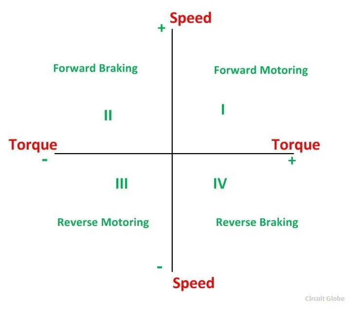
Four Quadrant Operation of any drives or DC Motor means that the machine operates in four quadrants. They are Forward Braking, Forward motoring, Reverse motoring and Reverse braking. A motor operates in two modes – Motoring and Braking. A motor drive capable of operating in both directions of rotation and of producing both motoring and regeneration is called a Four Quadrant variable speed drive.
QUADRANT-I
- When a motor draws power from supply, the voltage and current are in the same direction.
- Now the motor is said to be in motoring operation, its operation corresponds to first quadrant.
- In the first quadrant power developed is positive and the machine is working as a motor supplying mechanical energy. The I (first) quadrant operation is called Forward Motoring.
QUADRANT-II
- If there is a possibility of reversing the current direction keeping the voltage polarity same, the motor is said to be operating in second quadrant.
- This happens when regenerative braking is applied on the motor.
- During regeneration operation, reverse power flow will happen. ie, power will fed back to the supply system.
- Second quadrant operation is known as Braking. In this quadrant the direction of rotation is positive, and the torque is negative, and thus, the machine operates as a generator developing a negative torque, which opposes the motion.The kinetic energy of the rotating parts is available as electrical energy which may be supplied back to the mains. In dynamic braking dissipated the energy is dissipated in the resistance.
QUADRANT-III
- If the voltage polarity and load current are reversed simultaneously, the motor’s operation will be in the opposite direction ( but the power is consumed by the load).
- This operation is corresponds to the third quadrant and even now it is said to be in motoring operation (in reverse direction).
- The third quadrant operation is known as the reverse motoring. The motor works, in the reverse direction. Both the speed and the torque have negative values while the power is positive.
QUADRANT-IV
- If the voltage polarity is reversed maintaining the current direction from source to load, the power reversed and the operation corresponding to the fourth quadrant.
- Now the motor is said to be in reverse regeneration operation (ie, regeneration in reverse direction).
- In the fourth quadrant, the torque is positive, and the speed is negative. This quadrant corresponds to braking in the reverse regenerative braking mode.
FOUR QUADRANT CHOPPER CIRCUIT DIAGRAM:
FIRST QUADRANT(Forward Motoring)
When switch CH1 turned ON
In first quadrant an switch CH1 operated, Switches CH1 and CH2 conduct, output voltage V and the output current I both are positives, power flows from source to load and inductor stores energy while the motor rotates in the forward direction hence called forward motoring.
When switch CH1 turned OFF
While switch CH1 turned OFF but switch CH4 and diode D2 conducts output current I is positive and the output voltage V becomes zero. An induction release energy and freewheeling action using diode D2 takes place, the motor rotates in the forward direction hence called forward motoring.
SECOND QUADRANT(Forward Regenerative Braking)
When switch CH2 turned ON
Assume that the motor is running in the forward direction. Here switch CH2 operated, switch CH2 and diode D4 conducts, output voltage V is zero and Eb is responsible for the negative output current I, machine behave as generator and inductor stores energy.
When switch CH2 turned OFF
While switch CH2 turned off, diode D1 and diode D4 conducts, output voltage V becomes positive and the output current I is negative, inductor release energy using diodes D1 and D4 where power flows from load to source and hence called as reverse braking.
THIRD QUADRANT(Reverse Motoring)
When switch CH3 turned ON
The polarity of back emf Eb must be reversed. Here switch CH3 operated, switches CH3 and CH2 conducts output voltage V and the output current I both are negative. Power flows source to load and inductor stores energy therefore the motor rotates in reverse direction hence called as reverse motoring.
When switch CH3 turned OFF
While switch CH3 turned off but switch CH2 and diode D4 conducts, output current I is negative and the output voltage V becomes zero, inductor release energy and freewheeling action using diode D4 takes place hence the motor rotates in the reverse direction.
FOURTH QUADRANT(Reverse Regenerative Braking)
When switch CH4 turned ON
The polarity of back emf Eb must be reversed. let us assume that the motor is running in the reverse direction. Here switch CH4 operated, switches CH4 and diode D2 conducts, output voltage V is zero and Eb is responsible for the positive output current I. Thus machine behave as generator and inductor stores energy.
When switch CH4 turned OFF
While switch CH4 turned off, diode D2 and diode D3 conducts, output voltage V becomes negative and output current I is positive, inductor release energy using diodes D2 and D3. Thus power flows from load to source and hence called as reverse braking.
DC7 - Four-Quadrant Chopper 200 HP DC Drive
The 200 HP DC motor is separately excited with a constant 150 V DC field voltage source. The armature voltage is provided by an IGBT converter controlled by two PI regulators. The converter is fed by a 515 V DC bus obtained by rectification of a 380 V AC 50 Hz voltage source. In order to limit the DC bus voltage during dynamic braking mode, a braking chopperhas been added between the diode rectifier and the DC7 block.
The first regulator is a speed regulator, followed by a current regulator. The speed regulator outputs the armature current reference (in p.u.) used by the current controller in order to obtain the electromagnetic torque needed to reach the desired speed.
The speed reference change rate follows acceleration and deceleration ramps in order to avoid sudden reference changes that could cause armature over-current and destabilize the system.
The current regulator controls the armature current by computing the appropriate duty ratios of the 5 kHz pulses of the four IGBT devices (Pulse Width Modulation). For proper system behaviour, the instantaneous pulse values of IGBT devices 1 and 4 are opposite to those of IGBT devices 2 and 3. This generates the average armature voltage needed to obtain the desired armature current. In order to limit the amplitude of the current oscillations, a smoothing inductance is placed in series with the armature circuit.
OUTPUT:
COMPARISON OF FOUR-QUADRANT CHOPPER DC DRIVE (DC7) WITH H-BRIDGE:
In four quadrant chopper DC drive distributes required current supply for each sector and it consist of four quadrants like Forward Motoring, Forward Regenerative Braking, Reverse Motoring and Reverse Regenerative Braking. whereas H-bridge supplies an irregular current for each sector that causes voltage fluctuation in armature current. It consist of two operations they are Forward motoring, reverse motoring.
In modern battery charger for electrical vehicles, H-bridge circuits are used. A four-quadrant operation is required in industrial as well as commercial applications.
The efficiency is high in chopper compare with H-bridge, and maintenance is less than H-bridge.
In Robotics Technology, H-bridge circuits are used. Some other applications of four quadrant operation is engine test loading systems.
The regenerative braking is not possible in H-bridge while in chopper it is possible.
The most important application of the H-Bridge circuit as the motor driver circuit. H-bridge circuits can be placed in small places. Four quadrant chopper is lightweight in nature.
In H-bridge we need to change polarity which turns into opposite direction to control the motor whereas in chopper model we need to interrupt one signal under control of another.
STUDY-3:
3. To make a suitable EV model using DC7 block and make result report
EV model using DC7 block:
Method-1
The armature voltage is provided by an IGBT converter controlled by two PI regulators. The converter is fed by a 515 V DC bus obtained by rectification of a 380 V AC 50 Hz voltage source. In order to limit the DC bus voltage during dynamic braking mode, a braking chopper has been added between the diode rectifier and the DC7 block.
The first regulator is a speed regulator, followed by a current regulator. The speed regulator outputs the armature current reference (in p.u.) used by the current controller in order to obtain the electromagnetic torque needed to reach the desired speed. The speed reference change rate follows acceleration and deceleration ramps in order to avoid sudden reference changes that could cause armature over-current and destabilize the system.
The energy source of an EV is a battery or fuel cell. Let's take the case of a battery. To modify the energy source at the input side , you can take a generic battery model and configure it by referring to any datasheet, sheet related to an EV vehicle battery model. Otherwise give any driving cycle input replacing that input instead of default drive cycle. By inserting the datasheet with help of drive cycle source block and change the drive cycle source as workspace variable.
A speed reference and time period of duty cycle is obtain from the spreadsheet that are consider as input drive for EV model. Here the circuit model for EV is shown as below.
Here we creating a spreadsheet of time and speed of duty cycle in excel format. A unit of time and speed is represented in table. The run time is entered up to 20s and speed(RPM) is raised in between that period of time. In this table, the speed is reduced and being stoped at the end of cycle time.
The value of time and speed are assumed and entered in this table are shown as below.
An data from the spreadsheet is imported in Matlab script and taken as drive cycle data for EV model. The data of motor speed and time period is entered in that workspace whereas that data are taken to drive cycle data by Drive cycle source block.
The speed variation could occur during the cycle time according to the input we are given. A workspace table in Matlab is shown as below.
Drive cycle source block is used as speed reference in this EV model where the data is inserted by workspace in matlab. The source velocity units and output velocity units are changed as rpm. Speed reference is consider from the drive cycle source and motor speed are obtained from the spreadsheet table. The drive cycle source block are shown as below.
OUTPUT:
This graphs shows the various flow of energy that are armature voltage flow during duty cycle and armature current variations in duty cycle and the motor speed. During the 1&4 duty cycles flow of IGBT current is increased as 80% of the duty cycle this will happen when raise in speed. And it will back to thier actual flow when speed is decreased.
The instantaneous pulse values of IGBT device 1&4 are opposite to those of IGBT devices 2&3. This generates the average armature voltage needed to obtain the desired armature current.
At the duty cycle 2&3 the inverse action takes place and flow of IGBT current is passed in a negative direction. It reaches an maximum range of 90% of duty cycle in opposite direction due to increase in speed. When the speed decreases flow of current is low and reaches its actual flow. The flow of armature voltage is passed from negative terminal to the positive terminal.
An armature current obtain from the input data and it may vary according to the speed variation, when the motor speed is increase the current flow in the armature is also increases. Thus armature current increases gradually that depends upon consumption of power supply for drive train. It starts from 0 and flow increases up to 450A of current during the high speed of motor the current will raised. The fluctuation of current is appeared during this operation but minimized the amount of fluctuation is observed in this EV model.
The motor speed is raised in this output graph because of the raise in speed that is entered in the spreadsheet. It reaches 1500rpm of speed in a time period of 10s after that motor speed is decreased and back to its initial state that are mentioned in the drive cycle. Therefore EV model using DC7 block is simulated and results are obtained according to our specified inputs.
Method-2
By changing linear load torque as vehicle torque-speed characteristics:
In this method we change the Ac voltage and removed the AC to DC converter block. This AC to DC converter block is only used for conversion of AC to DC power supply here we are using DC voltage source directly. In this supply a DC voltage source is connected to RLC series block and to the braking chopper. The v-bridge positive and v-bridge negative is connected to DC voltage source. A power supply from DC voltage is connected to vcc and ground of four-quadrant chopper dc drive.
At the previous method, we consider linear load torque(default torque of fan) is assumed as vehicle torque of EV and execute the output for that load torque where the speed during duty cycle is obtained from spreadsheet data.
Vehicle torque-speed characteristics are obtained from the equation of speed characteristics and torque characteristics. The torque of the motor is provided base on input speed of vehicle driven during the duty cycle.
The subsystem of vehicle torque-speed characteristics is explained as the block diagram in Simulink that is shown below. These equations are analyzed from challenge 6 to calculate the speed of motor. An equation of vehicle characteristics is given below,
Tm= 24.72+0.0051*Wm^2
The speed Wm is considered as the input source for this equation, therefore vehicle characteristics are evaluated in this equation to find torque of the motor. When the speed is varied by increased level a torque also raised and decreases in torque lead to a reduction of speed. Here the speed and time is obtained from drive cycle source.
The speed is regulated into torque-speed characteristics block and the calculation is done by subsystem of vehicle characteristics equation. Therefore the resultant torque is analyzed as output torque of motor. That connection is shown as below,
OUTPUT:
The actual motor speed and Obtained motor speed is same from this graphical representation and shoot up in armature current is appeared in this due to voltage fluctuation, when the rise in the speed of vehicle. Therefore EV model using DC7 block is simulated and results are obtained according to our specified inputs.
CONCLUSION:
All the above three study shows that difference between the H-bridge model and Four quadrant chopper (DC7) model. The advantages and applications of these two models are also explained in the above study. Each model has their individual specialties that may based on the application of the motor. In H-bridge the motor is controlled by changing the polarity which turns into opposite direction. In chopper model we need to interrupt one signal under control of another. The EV model using DC7 block is also simulated and results are obtained according to our specified inputs.