Calculating The Equlibirum Points And Steady Point Of Drive Using Matlab
AIM:
- To study the Induction motor operation.
- To calculate the starting time of a drive with the given parameters.
- To explain the stability of a drive with the given parameters.
OBJECTIVE:
- Study of induction motor operation and analysis of how the induction motor similar to the clutch.
- Calculating the starting time of a drive with the following load torque and motor torque equation.
- Calculating the stability and equilibrium points of the drive with the following load torque and motor torque equation.
KEYWORDS: Induction motor, synchronous speed, electromagnetic clutch.
SOFTWARE USED: Matlab.
DEFINITION:
STUDY-1:
INDUCTION MOTOR:
Nikola Tesla invented the induction motor with a rotating magnetic field that made unit drives for machines feasible and made AC power transmission for economic necessity. The induction motor has two main parts stator(stationary part) and rotor(rotating part). The stator is basically at three coil winding and three-phase power input is given to it. The Winding passes to slots of the stator made by stacking fin.
An induction motor (also known as an asynchronous motor) is a commonly used AC electric motor. In an induction motor, the electric current in the rotor needed to produce torque is obtained via electromagnetic induction from the rotating magnetic field of the stator winding. The rotor of an induction motor can be a squirrel cage rotor or wound type rotor.
Induction motors are referred to as ‘asynchronous motors’ because they operate at a speed less than their synchronous speed.
Theory of Operation of Induction Motors
In both induction and synchronous motors, the AC power supplied to the motor's stator creates a magnetic field that rotates in synchronism with the AC oscillations. Whereas a synchronous motor's rotor turns at the same rate as the stator field, an induction motor's rotor rotates at a somewhat slower speed than the stator field. The induction motor stator's magnetic field is therefore changing or rotating relative to the rotor. This induces an opposing current in the induction motor's rotor, in effect the motor's secondary winding, when the latter is short-circuited or closed through an external impedance. The rotating magnetic flux induces currents in the windings of the rotor, in a manner similar to currents induced in a transformer's secondary winding(s).
The induced currents in the rotor windings in turn create magnetic fields in the rotor that react against the stator field. The direction of the magnetic field created will be such as to oppose the change in current through the rotor windings, in agreement with Lenz's law. The cause of induced current in the rotor windings is the rotating stator magnetic field, so to oppose the change in rotor-winding currents the rotor will start to rotate in the direction of the rotating stator magnetic field. The rotor accelerates until the magnitude of induced rotor current and torque balances the applied mechanical load on the rotation of the rotor. Since rotation at synchronous speed would result in no induced rotor current, an induction motor always operates slightly slower than synchronous speed.
For rotor currents to be induced, the speed of the physical rotor must be lower than that of the stator's rotating magnetic field otherwise the magnetic field would not be moving relative to the rotor conductors and no currents would be induced. As the speed of the rotor drops below synchronous speed, the rotation rate of the magnetic field in the rotor increases, inducing more current in the windings and creating more torque. The ratio between the rotation rate of the magnetic field induced in the rotor and the rotation rate of the stator's rotating field is called "slip". Under load, the speed drops and the slip increases enough to create sufficient torque to turn the load. For this reason, induction motors are sometimes referred to as "asynchronous motors".
Slip  , is defined as the difference between synchronous speed and operating speed, at the same frequency, expressed in rpm, or in percentage or ratio of synchronous speed. Thus

where is stator electrical speed,
  is rotor mechanical speed.
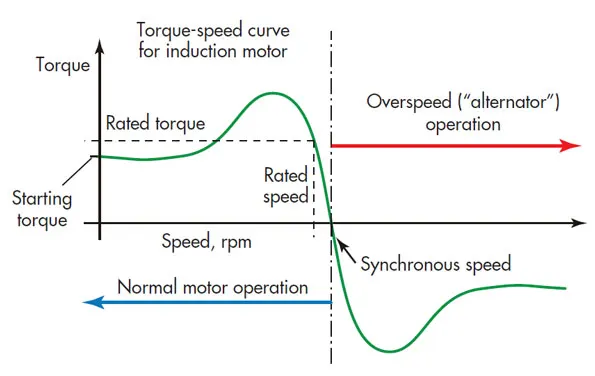
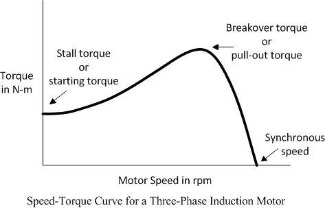
The power loss equation is given below,
Pr:Pcr:Pm = 1:s:(1-s)
where , Pr = Power Applied to the rotor
Pcr = Rotor losses
Pm = Mechanical power
There will be losses are acting during the transmission of power and variations in rotational of winding leads to losses of speed in motor. The input current is processed to stator and rotor rotates the connected shaft by the magnetic field of winding and output are obtained by it. During that operation, there will be losses in the speed of motor from the stator to rotor of the motor.
The speed losses in a motor are given below,
`omega m` = `omega ms` .(1-s)
where , `omega m` = Rotor speed
`omega ms` = Stator Synchronous Speed
s = Slip
CLUTCH:
A Clutch is a mechanical device that is used for transferring power from one part of an engine to another. A typical example is an automobile. The reciprocating action of the piston inside the engine produces power. The power generated/provided by the engine is transmitted via a clutch to the wheels through gears to the transmitting shaft. The gears are of various diameters and hence they could control the speed of rotation. The clutch works by engaging and disengaging the gear from the transmitting shaft.
ELECTROMAGNETIC CLUTCH:
The main components of the EM clutch are a coil shell, an armature, rotor, and hub. The armature plate is lined with friction coating. The coil is placed behind the rotor. When the clutch activated the electric circuit energizes the coil, it generates a magnetic field. The rotor portion of clutch gets magnetized. When the magnetic field exceeds the air gap between rotor and armature and then it pulls the armature toward the rotor. The frictional force generated at the contact surface transfer the torque. Engagement time depends on the strength of magnetic fields, inertia, and air gap.
When voltage is removed from the coil, the contact is gone. In most design a spring is used to hold back the armature to provide an air gap when current is removed.
EDDY CURRENT CLUTCH:
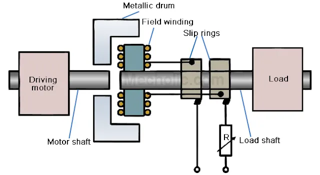
An eddy current clutch and an induction machine are identical in working principle. The input shaft directly coupled to the motor and variable speed output shaft is connected to load. A metallic drum is connected to the driving shaft and a field coil system is mounted on the output shaft. The slip rings used to excite the field system. The load is initially at rest when the motor reaches the full speed; DC current is passed through the electromagnets. The resultant magnetic field produced an eddy current in the metallic drum. The magnetic flux produces a torque that brings the load to the desired speed.
Loss = Input Power - Output Power
Input power = T.`omega1`
Output power = T.`omega2`
where, T= Torque of input and output shafts
Loss = T.`omega1`- T`omega2`............Equation(1)
The clutch losses are given below,
`omega2` = `omega1`.(1-s)
where
`omega1` = Speed of driving shaft
`omega2` = Speed of driven shaft
s = slip (The difference between the driving and driven due to losses)
Substitute the value of `omega2` in equation(1)
Loss = T.`omega1`- T(`omega1`(1-s))
Loss = (1-s).T
The output from the rotor of the induction motor shaft is connected to clutch. Eddy current clutches are so named because they induce eddy currents into a metal cylinder or drum. One part of the clutch contains slip rings and a winding. The rotor is constructed so that when the winding is excited with direct current, magnetic pole pieces are formed. The rotor in motor is connected to driving motor input of clutch. The rotor is the input of the clutch and is connected to an AC induction motor. The rotor is mounted between the metallic drum and field winding of clutch that forms output shaft of the clutch. When the rotor transfers the force for clutch. A current is applied for driving motor(rotor) directly, the spinning electromagnets induce eddy currents into the metal drum. The magnetic fields of the rotor and drum are attracted to each other, and the clutch turns in the same direction as the motor.
Once it reaches the high level of torque to obtain the constant speed the clutch is engaged to the output shaft of the driving vehicle. The main advantage of an eddy current clutch is that there is no mechanical connection between the rotor and drum. Since there is no mechanical connection, there is no friction to produce excessive heat and there is no wear as is the case with mechanical clutches.A clutch engaged and disengaged are based on the maximum speed of rotor obtain from the motor to clutch. The speed of the clutch can be controlled by varying the amount of direct current applied to the armature or rotor. Since the output speed is determined by the amount of slip between the rotor and drum, when the load is added, the slip will become greater, causing a decrease in speed. This can be compensated for by increasing the amount of direct current applied to the rotor. Many eddy current clutch circuits contain a speed sensing device that will automatically increase or decrease the DC excitation current when load is added or removed.
Therefore the operation of the induction motor and the clutch are similar to each other, By increasing the motor speed the direct current is obtained by the rotor and it transfers the current to drum and field winding thus they engaged with motor and clutch also rotates as the same direction of a motor. After the speed changes the disengagement is appeared and the clutch is released for fraction of seconds and engaged while it reaches the constant speed.
STUDY-2:
To calculate the starting time of a drive with the following parameters:
Given Data:
J=10 kg-m2,
T = 15 + (0.5 .ωm)
Tl=5+ (0.6 .ωm)
To Find:
A starting time of the drive
Solution:
The basic fundamental equation of motor load system can be represented as
T-Tl = d/dt(J.ωm)
To differentiate this equation with uv formula
uv = uv' + vu'
(e.g) Here u = J and v = ωm
T-Tl = d/dt(J.ωm) = J(dωm/dt) + ωm(dJ/dt)
where, T = Torque of motor
Tl = Load Torque
ωm = Motor Speed
J = Moment of inertia of motor
t = Starting time
From the above equation
consider the drive with constant inertia dJ/dt=0. Therefore the equations becomes,
T-Tl = J(dωm/dt)..........(1)
Now substituting the value of T and Tl in equation (1)
(15+(0.5)*ωm) - (5+(0.6)*ωm) = 10*(dωm/dt)
10-0.1ωm = 10*(dωm/dt)
10*(1-0.1/10.ωm) = 10*(dωm/dt)
(1-0.01.ωm) = (dωm/dt)
By rearranging this equation we get,
dt = dωm/1-0.01.ωm.........(2)
Now integrating equation (2) on both sides
`int`dt = `int(domegam)/(1-0.01.omegam`
t = `int(domegam)/(1-0.01.omegam`.........(3)
we consider v=1-0.01 .ωm
differentiating v on both sides,
dv/dωm = -0.01
Integrate this equation
t = `int(domegam)/v.(dv)/(domegam)`
t = `int(1/v)dv`
t = -100ln(v)
t = -100ln(1-0.01ωm)........(4)
For steady state , T-Tl = 0
substitute T-Tl = 0 in fundamental equation
(15+(0.5)*ωm) - (5+(0.6)*ωm) = 0
10-0.1ωm = 0
-0.1ωm = -10
ωm = 10/0.1=100
ωm = 100 rad/sec
transient operation over time is considered to be over 95% change in speed taken place. Therefore final speed ωm2 will be 95% of speed ωm
ωm2 = 100*95/100 = 95rad/sec
Applying in equation (4)
t = -100ln(1-0.01*95)
t = -100ln(1-0.95)
=-100ln(0.05)
t = -100(-2.9957)
t = 299.57sec
The starting time of the drive is 299.57sec
DERIVATION AS MATLAB PROGRAM:
(a) Calculating Equilibrium Points
clear all
close all
clc

%calculating the equilibrium points
w = linspace(0,150);
Tm = 15+(0.5*(w));
Tl = 5+(0.6*(w));
%plotting the omega and motor torque that represented as red colour
plot(w,Tm,'r')
title('Determining Equilibrium points')
xlabel('Omega (rad/s)')
ylabel('Torque (N-m)')
hold on
%plotting the omega and load torque that represented as blue colour
plot(w,Tl,'b')
legend('Motor Torque','Load torque')
grid on
Here w is considered as linspace value of 0 to 150. Whereas the motor torque value and load torque value is equated as by given in the question. Now the value of w is equated in that motor torque load and load torque equation up to 150 value. Therefore w will obtain 150 points that point are considered as equilibrium points. By plotting the motor torque value of w with the load torque value with speed w an intersection point is obtained that value is w = 100 rad/sec.
OUTPUT:
The output value is w = 100rad/sec as we derived by the equation.
(b) Calculating the starting time of the drive
clear all
close all
clc

t_p = [0 299.57];
ic = [0 0];
% using ode45 solver we obtain w for each time span and initial condition
[t,w] = ode45(@omega,t_p,ic);
plot(t,w)
title('w-dot (dw/dt)')
xlabel('time (sec)')
ylabel('omega (rad/s')
grid on

%function program
%Here we comsider w_dot = 1-0.01*(w) and equate in main program for
%differentiation as solver ode 45
function [w_dot] = omega(t,w)
w_dot = 1-0.01*(w);
end
In this program, we calculate the constant speed of the motor through derivation of w(dw/dt). We are using time of 0 to 299.57sec because we derived the equation above and obtained this time value whereas initial condition is referred in the program. The Function program is called here in main program for ode 45 solver to differentiate at each time. The function is named as omega(t,w) and the equation is w_dot = 1-0.01*(w). These equation is differentiated in that solver up to the 299.57sec. Therefore the constant speed of the drive is obtained in time t= 299.57sec as we discussed in study-2 equations.
OUTPUT:
The starting time of the drive is 299.57sec
STUDY-3:
To calculate the stability and equilibrium points of the drive with the following load torque and motor torque equation:
Given Data:
Tm=(1+2ωm)
Tl= 3 √ωm
To Find:
The stability and equilibrium points of the drive
Solution:
General conditions:
Condition for stability:
`(dTl)/(domegam)-(dTm)/(domegam)>0`
If dωm>0 , Tl>Tm
dωm<0 , Tm>Tl
where,
Tm = Torque of motor
Tl = Load Torque
ωm = Speed of motor in rpm
At steady-state stability
Tm = Tl
equating both the values,
1+2ωm = 3 √ωm
By solving this equation we obtain two equilibrium points ωm = 0.25 and 1
DERIVATION AS MATLAB PROGRAM:
Calculating Equilibrium Points
%calculating equilibrium points

clear all
close all
clc
%Here Tm and Tl values are taken from study-3
w = linspace(0,2);
Tm = 1+(2*w);
Tl = 3* sqrt(w);
%plotting the omega and motor torque that represented as red colour
plot(w,Tm,'r')
title('Determining equilibrium points')
xlabel('Omega (rad/s)')
ylabel('Torque (N-m)')
hold on
%plotting the omega and load torque that represented as blue colour
plot(w,Tl,'b')
legend('motor torque','load torque')
grid on
This program is executed as same as the study-2 for calculating the equilibrium point of the drive.
OUTPUT:
The two equilibrium points are obtained in this graph that are initiated as two dots and the values of ωm = 0.25 and 1 .
Now we differentiate the load torque and motor torque interms of motor speed, therefore we get
Tl = (3)/(2).√ωm
Tm = 2
We substitute the value of motor speed ωm = 0.25 and 1 in this equation Tl and Tm to obtain stability points.
i. sub ωm = 0.25 in that equation
Tl = (3)/(2).√0.25
Tl = 3
Hence Tl = 3 and Tm = 2 are obtained in motor speed of ωm = 0.25 , according to the conditions of stability the value of load torque is greater than value of the motor torque that system is considered as a stable condition. Whereas by applying the speed of ωm = 0.25 in the differential equations of load torque and motor torque. So the value ωm = 0.25 is the stability of a drive.
ii. sub ωm = 1 in that equation
Tl = (3)/(2).√(1)
Tl = 1.5
Hence Tl = 1.5 and Tm = 2 are obtained in the motor speed of ωm = 1 , according to the conditions of stability the value of load torque is lesser than value of the motor torque that system is considered as an unstable condition. In this case, the load torque is lesser than the motor torque by substituting the speed of ωm = 1 in the differential equations of load torque and motor torque. Therefore, the system will be unstable. So the value ωm = 1 is not stability point of the drive.
CONCLUSION:
The similarities of induction motor and clutch are explained, and the calculation for the starting time of a drive with the given parameters are derived using Matlab. The equilibrium points of drive and stability of drive are also obtained by deriving load torque and motor torque equation. The stability conditions are also applied to analyze the steady point of drive.