Week 9-Challenge
OBJECTIVE:
To Mesh the given Component with a Mesh size of 5mm.
Create connector and Attach the various parts of the given model
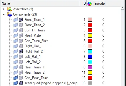
1. Right_Rail_2 & Front_truss_1:- Seam-Quad(angled+capped+L)
2. Left_Rail_2 & Front_truss_1:- Quad elements
3. Front_truss_2, Front_truss_1 & Right_Rail_1:- Spot weld with 3 Layers and 5 mm Diameter
4. Front_truss_2, Front_truss_1 & Left_Rail_1:- Hexa (Adhesive)
5. Rear_truss_2 & Right_Rail_2:- Bolt Connector
6. Rear_truss_2 & Left_Rail_2:- Bolt Connector
7. Right_Rail_1 & Right_Rail_2:- Spot-weld with Rigid Elements
8. Left_Rail_1 & Left_Rail_2:- Spot-weld with Spring Elements
9. Rest all the component left Join them with suitable connectors.
DEFINITION:
1D Elements are simple connections between nodes. Standard 1D Elements are,
RBE2 Rigid link to transfer motion from the independent node to the dependant node(s).
RBE3 Rigid link to distribute loads. Will not induce stiffness.
Beam/Bar Non-Rigid Link that has properties that include cross-section and material definitions.
Purpose of Connectors:
Geometric entities that define connections between other entities
- Used for welding, bolts, adhesives, etc.
- Link geometry or FE entities
- Can be “realized” into FE representations of welds, etc. for any supported solver
- rigid, CWELDs, MAT100s, ACMs, etc.
- Connectors allow for easy and rapid:
- Creation of FE welds, bolts, adhesives, etc.
- interactively or from:
- XML file
- MCF (master connectors file)
- Spot welds only
- Switching between different FE configurations of welds, bolts, adhesives, etc.
- Part swapping and reconnection
- Replacement by names or IDs
PROCEDURE:
- First, we want to import the model by selecting file>open>model>select that frame_assembly_welding and click open to obtain the model in the graphical area. The selection process is shown below,
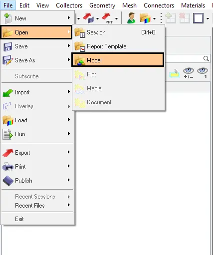
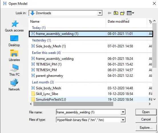
Fig: Import option
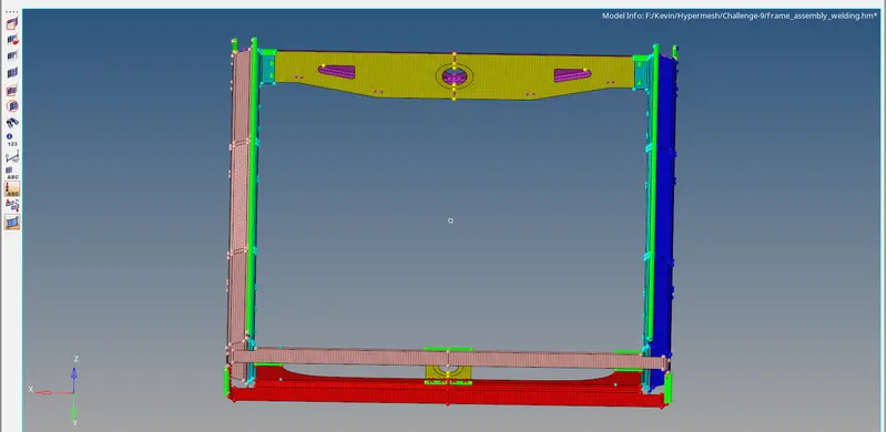
- The model will be shown in the graphical area after importing the file and the model is shown below,
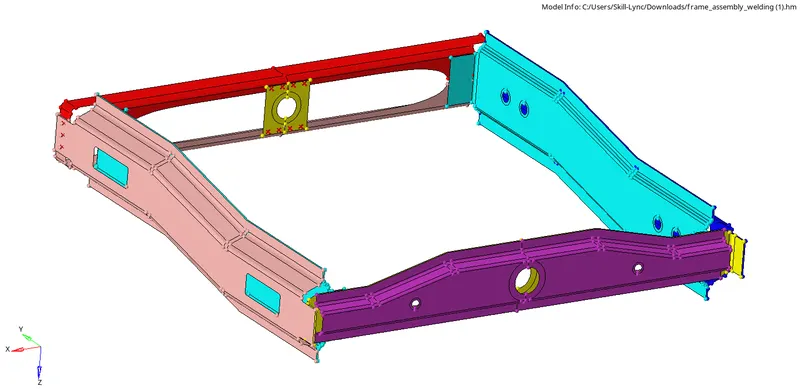
Fig: Open model
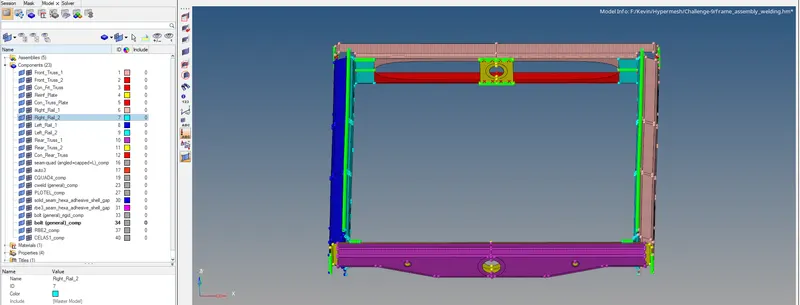
- The different components image are shown below,
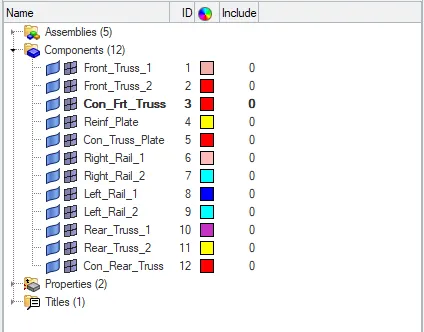
Fig: Components
- Now we want to mesh the component by selecting 2D mesh>auto mesh or click F12 key to enter auto mesh option then select surfs and give the element size as 5mm and select mesh option to generate a mesh in that component.
- The selection process is stated as below,
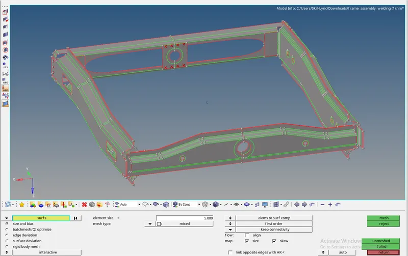
- Therefore a mesh is generated and they are shown below,
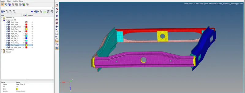
1. Right_Rail_2 & Front_truss_1:- Seam-Quad(angled+capped+L)
To connect the components using 1D connectors as per the mentioned type that is given by an instructor. First, enable the components Right_Rail_2 & Front_truss_1 to connect with each other. The components are shown below,
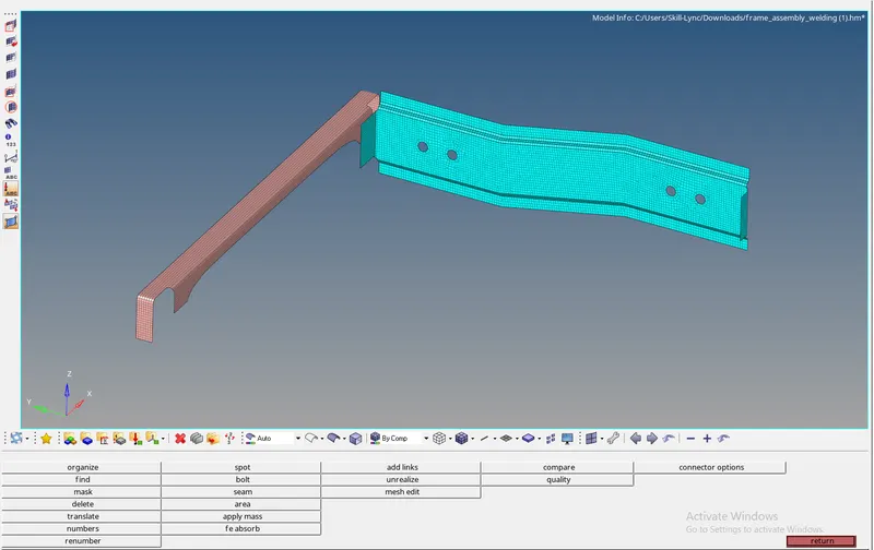
Now select the 2D>connectors>seam option and select type as seam-quad(angled+clapped+L). Then select the nodes and components and set spacing as 5 and tolerance as 10 and click create. A selection process is shown below,


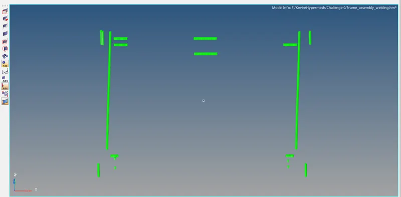
The nodes and components are selected which is shown below image and the connectors seam-quad(angled+clapped+L) are created.
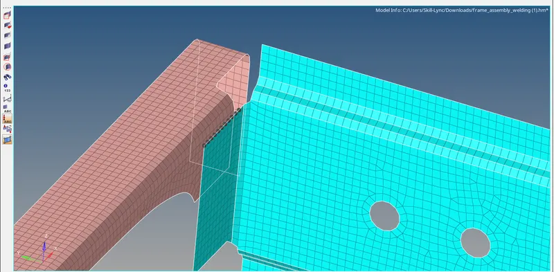
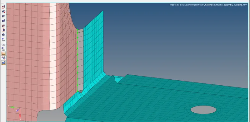
The created component for the type of seam-quad(angled+clapped+L) connector is shown below,
2. Left_Rail_2 & Front_truss_1:- Quad elements
To connect the components using 1D connectors as per the mentioned type that is given by an instructor. First, enable the components Left_Rail_2 & Front_truss_1 to connect with each other. The components are shown below,
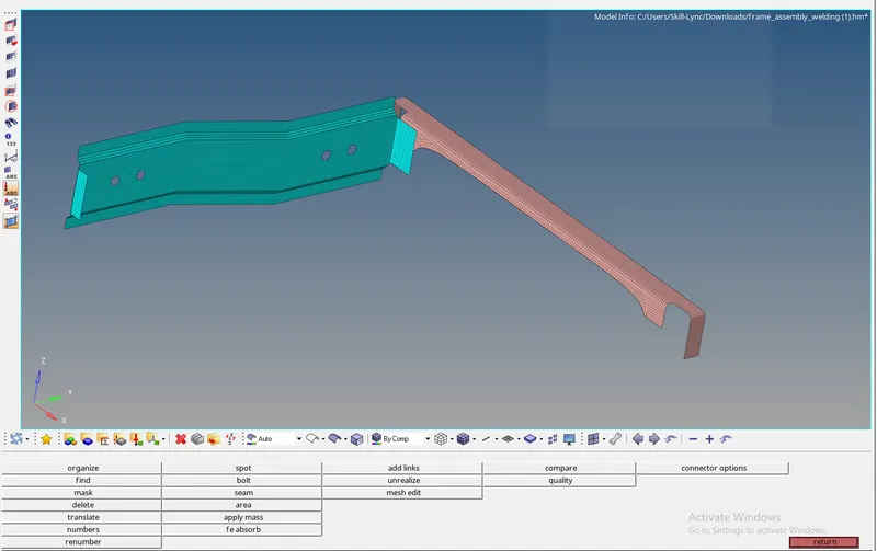
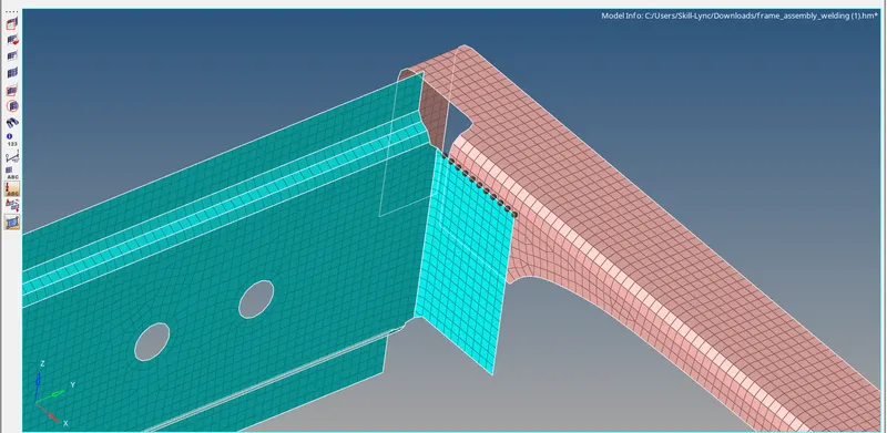
Now select the 2D>connectors>seam option and select type as Quad elements. Then select the nodes and components and set spacing as 5 and tolerance as 10 and click create. A selection process is shown below,

The nodes and components are selected which is shown below the image and the connectors Quad elements are created.
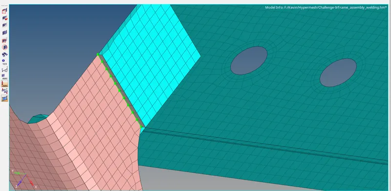
The created component for the type of Quad elements connector is shown below,
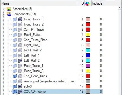
3. Front_truss_2, Front_truss_1 & Right_Rail_1:- Spot weld with 3 Layers and 5 mm Diameter
To connect the components using 1D connectors as per the mentioned type that is given by an instructor. First, enable the components Front_truss_2, Front_truss_1 & Right_Rail_1 to connect with each other. The components are shown below,
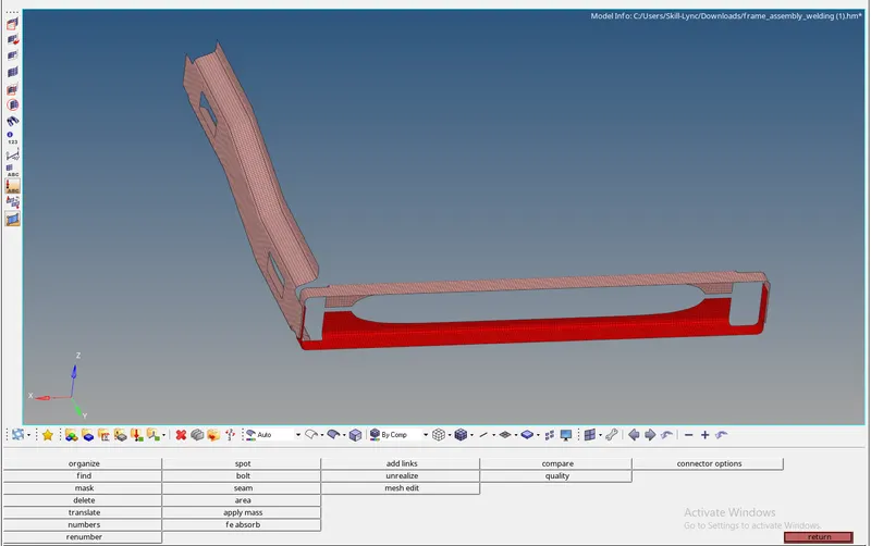
Now select the 2D>connectors>Spot weld option and select type as Cweld(general). Then select the nodes and components and set diameter as 5 and tolerance as 10 and set the number of layers as 3 to connect 3 components finally click create. A selection process is shown below,


The nodes and components are selected which is shown below the image and the connectors Spot weld is created.
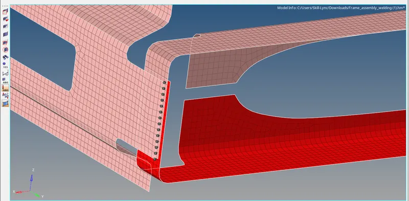
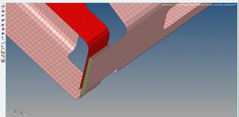
The created component for the type of Spot weld connector is shown below,
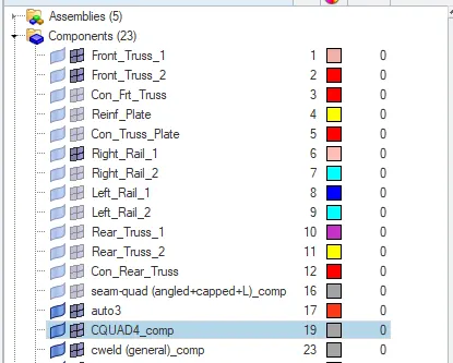
4. Front_truss_2, Front_truss_1 & Left_Rail_1:- Hexa (Adhesive)
To connect the components using 1D connectors as per the mentioned type that is given by an instructor. First, enable the components Front_truss_2, Front_truss_1 & Left_Rail_1 to connect with each other. The components are shown below,
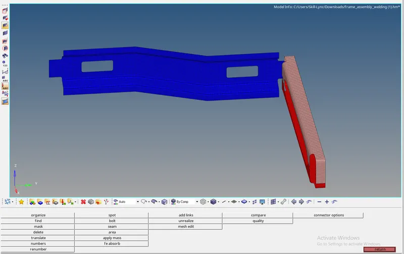
Now select the 2D>connectors>seam option and select type as Hexa (Adhesive). Then select the nodes and components and set spacing as 5, tolerance as 10, width as 5, and click create. A selection process is shown below,

The nodes and components are selected which is shown below the image and the connectors Hexa (Adhesive) is created.
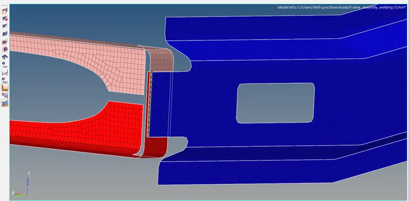
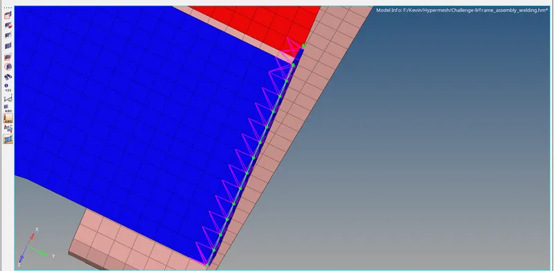
The created component for the type of Hexa (Adhesive) connector is shown below,
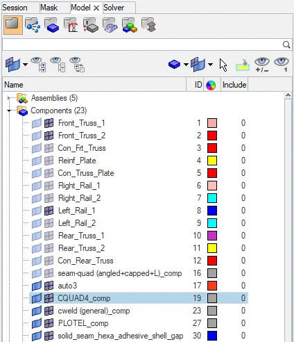
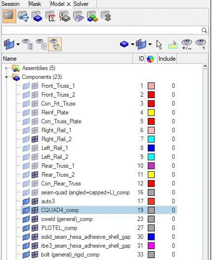
5. Rear_truss_2 & Right_Rail_2:- Bolt Connector
To connect the components using 1D connectors as per the mentioned type that is given by an instructor. First, enable the components Rear_truss_2 & Right_Rail_2 to connect with each other. The components are shown below,
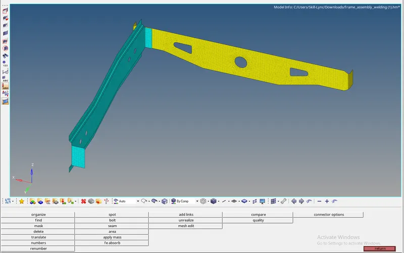
Now select the 2D>connectors>Bolt option and select type as Bolt general. Then select the nodes and components and set tolerance as 10, select the option as create hole, if none, and click create. A selection process is shown below,

The nodes and components are selected which is shown below the image and the connectors Bolt Connector is created.
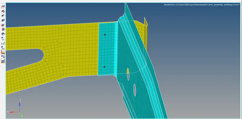
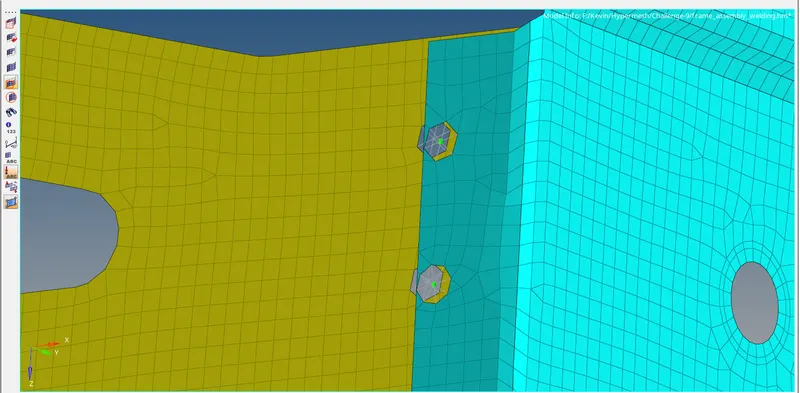
The created component for the type of Bolt Connector is shown below,
6. Rear_truss_2 & Left_Rail_2:- Bolt Connector
To connect the components using 1D connectors as per the mentioned type that is given by an instructor. First, enable the components Rear_truss_2 & Left_Rail_2 to connect with each other. The components are shown below,
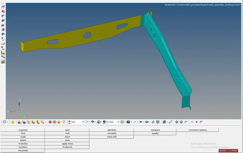
Now select the 2D>connectors>Bolt option and select type as Bolt general. Then select the nodes and components and set tolerance as 10, select the option as create hole, if none, and click create. A selection process is shown below,

The nodes and components are selected which is shown below the image and the connectors Bolt Connector is created.
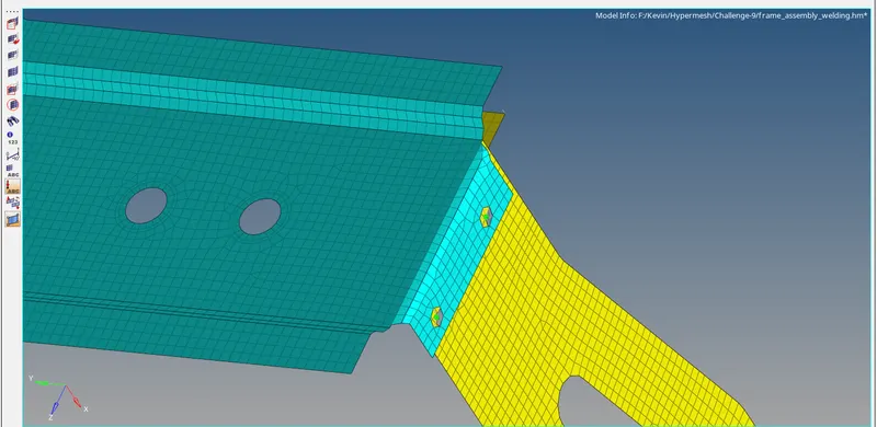
The created component for the type of Bolt Connector is shown below,
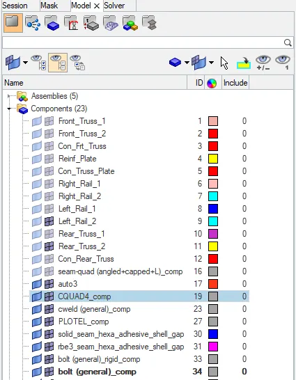
7. Right_Rail_1 & Right_Rail_2:- Spot-weld with Rigid Elements
To connect the components using 1D connectors as per the mentioned type that is given by an instructor. First, enable the components Right_Rail_1 & Right_Rail_2 to connect with each other. The components are shown below,
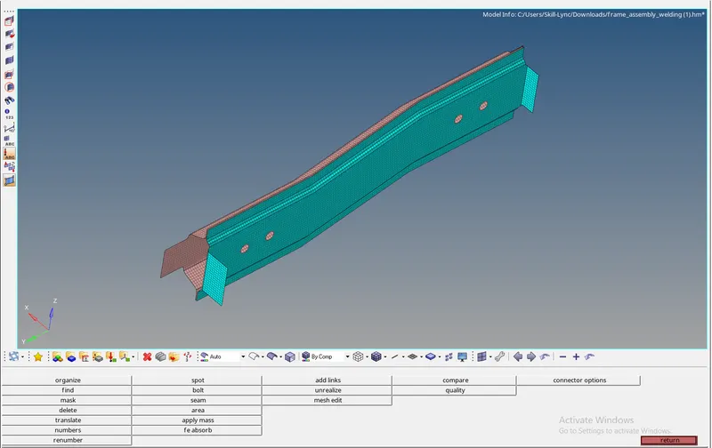
Now select the 2D>connectors>spot option and select type as rigid. Then select the nodes and components and set tolerance as 10, diameter as 5, and click create. A selection process is shown below,

The nodes and components are selected which is shown below the image and the spot Connector is created.
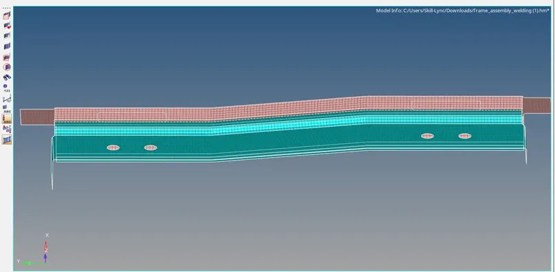
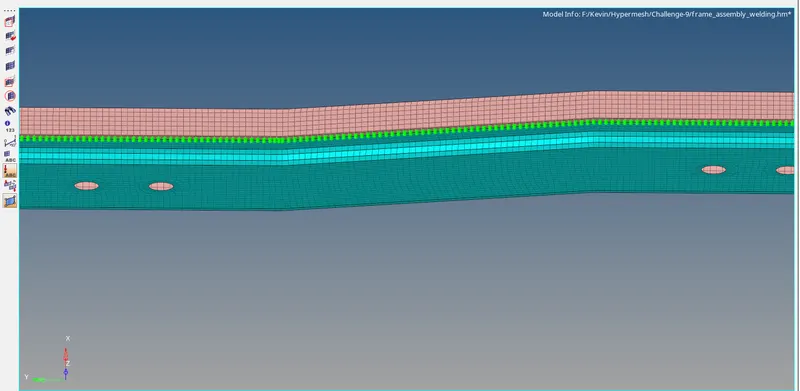
The created component for the type of spot Connector is shown below,
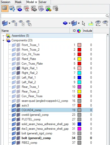
8. Left_Rail_1 & Left_Rail_2:- Spot-weld with Spring Elements
To connect the components using 1D connectors as per the mentioned type that is given by an instructor. First, enable the components Left_Rail_1 & Left_Rail_2 to connect with each other. The components are shown below,
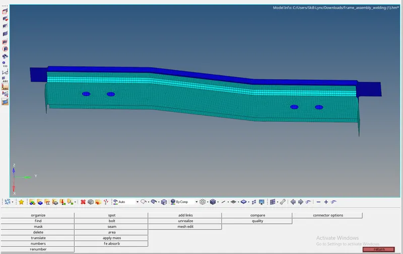
Now select the 2D>connectors>spot option and select type as spring. Then select the nodes and components and set tolerance as 10, diameter as 5, and click create. A selection process is shown below,

The nodes and components are selected which is shown below the image and the spot Connector is created.
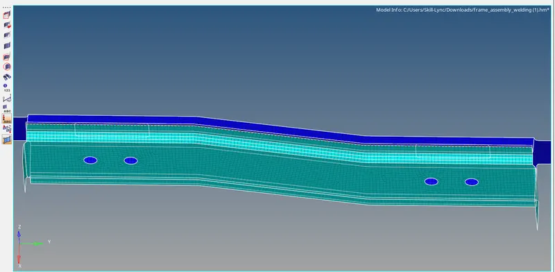
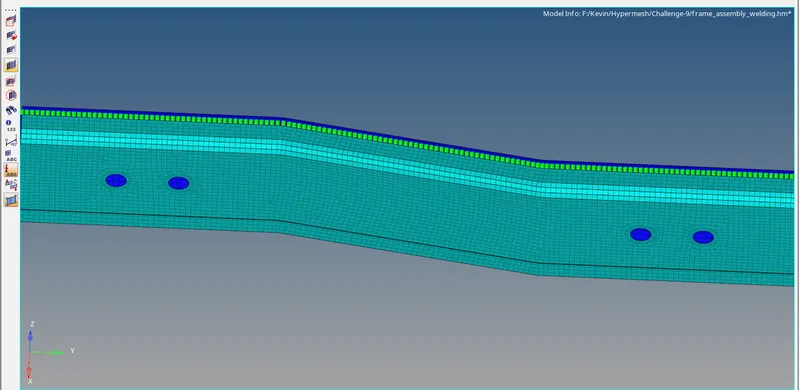
The created component for the type of spot Connector is shown below,
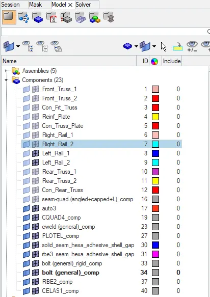
9. Rest all the components left Join them with suitable connectors.
The rest of all components are connected with the spot and the seam connectors.
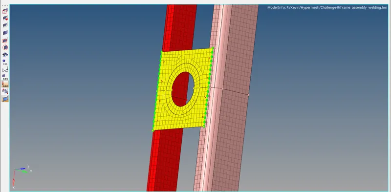
A spot connector is generated by selecting the 2D>connectors>spot option and select type as plot. Then select the nodes and components and set tolerance as 10, diameter as 5, and click create. A selection process is shown below,

The nodes and components are selected which is shown below the image and the spot Connector is created.
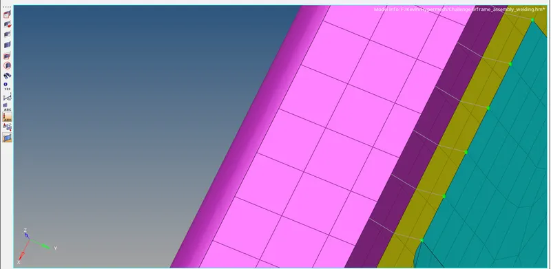
The seam connector is generated by selecting the 2D>connectors>seam option and select type as a plot. Then select the nodes and components and set spacing as 5 and tolerance as 10 and click create. A selection process is shown below,

The nodes and components are selected which is shown below the image and the seam connector is created.
CONCLUSION:
Therefore all the components are connected through connectors with the respective type mentioned by the instructor. Hence the model with connectors are shown below,