Week-7 Head Impact
Objective - To perform Head impact analysis and predict HIC values and further check if it is below the limiting standards of FMVSS 201U.
Case 1 - Simple Head Impact on a Rigid Wall
Model considered for analysis -
Shell Elements for Head and Rigid Wall for Hood
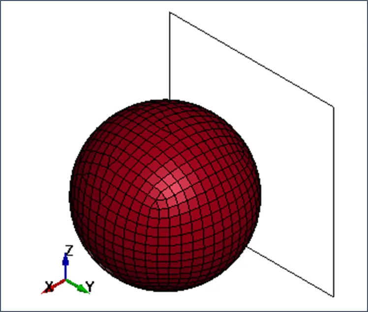
Units System considered – Kg-mm-ms
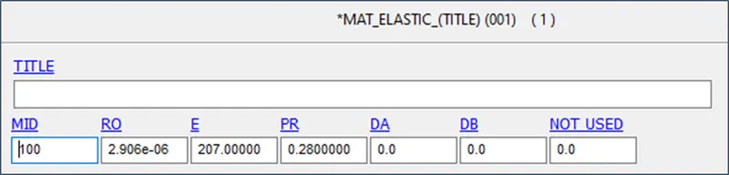
Elastic material for Head with properties –
RO = 2.906E-06 Kg/mm3
PR = 0.28
E = 207 GPa
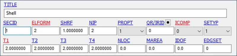
Section –
Shell Properties with
ELFORM=2
Thickness = 2 mm
Boundary Conditions -
Units System considered – Kg-mm-ms
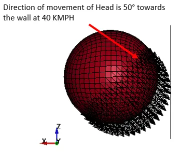
Initial Velocity applied = 40 KMPH in (-X,-Z), at 50° angle
40 KMPH = 11.11 mm/ms
Considering 50° angle for Cos component (X direction)
and (90°-50°) for Sin component (Z direction)
VX & VZ = -7.1413002 mm/ms

Output Requests -
Control termination – 10 ms
Output Requests –
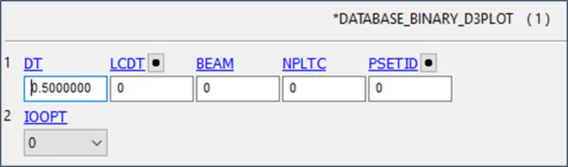
Database > Binary D3PLOT at DT 0.5 ms
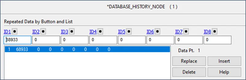
Database > ASCII option – GLSTAT, NODOUT AT DT= 0.5 ms

Energy Plots -
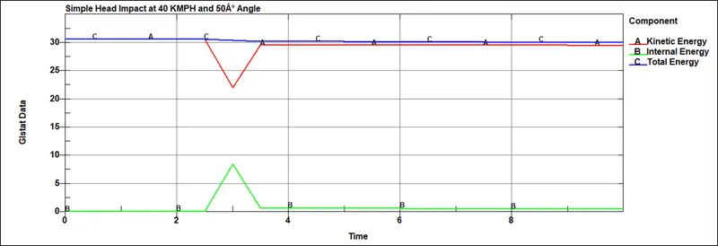
A certain drop in kinetic energy could be seen from the graph which is at the time of impact but from the behavior of the graph it is visible kinetic energy remains constant after certain decrease. Hence this case cannot be considered for real life scenario.
Acceleration Plot -
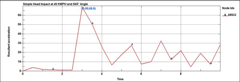
Max Acceleration at Head body after Impact = 68.9 mm/ms
HIC Plot -
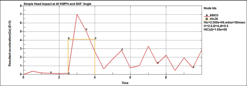
HIC = 2.055E+06
HIC(d) = 1.55E+06
CASE 2 –Headform Impact on a Rigid Wall
Model considered for analysis -
Solid Elements for Headform and Rigid Wall for Hood
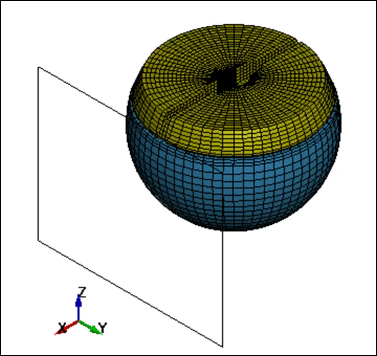
Units System considered – Kg-mm-ms
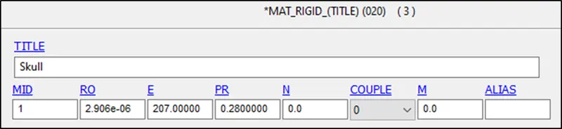
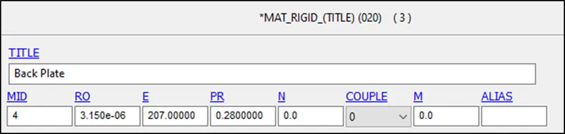
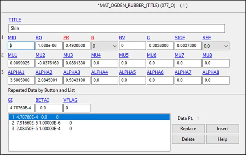
Rigid material for Skull & Back Plate with properties –
RO = 2.906E-06 Kg/mm3 for Skull
RO = 3.15E-06 Kg/mm3 for Back Plate
PR = 0.28
E = 207 GPa
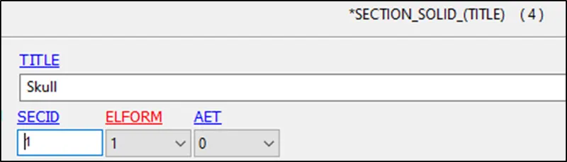
Section –
Solid Properties with
ELFORM = 1
Boundary Conditions -
Units System considered – Kg-mm-ms
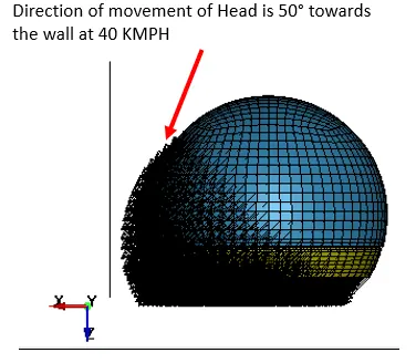
Initial Velocity applied = 40 KMPH in (X,-Z), at 50° angle
40 KMPH = 11.11 mm/ms
Considering 50° angle for Cos component (X direction)
and (90°-50°) for Sin component (Z direction)
VX = 7.1413002 mm/ms
VZ = -7.1413002 mm/ms

Output Requests -
Control termination – 10 ms
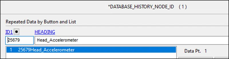
Output Requests –
Database > Binary D3PLOT at DT 0.5 ms
Database > ASCII option – GLSTAT, NODOUT AT DT= 0.5 ms
Energy Plots -
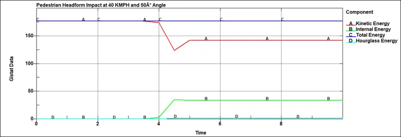
A certain drop in kinetic energy could be seen from the graph which is at the time of impact but from the behavior of the graph it is visible kinetic energy remains constant after certain decrease. Hence this case cannot be considered for real life scenario.
Acceleration Plot -
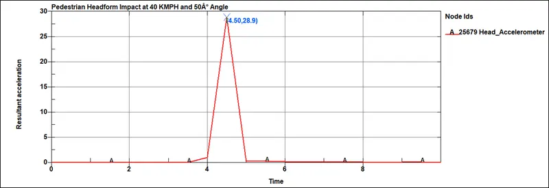
Max Acceleration at Head body after Impact = 28.9 mm/ms
HIC Plot -
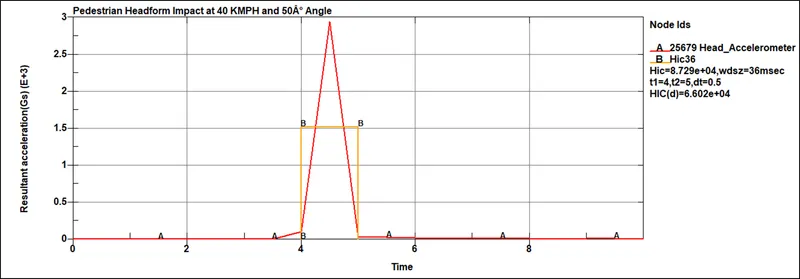
HIC = 8.729E+04
HIC(d) = 6.602E+04
CASE 3 –Headform Impact on a Meshed Hood
Model considered for analysis -
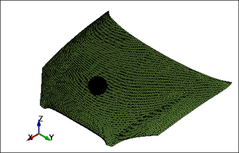
Solid Elements for Headform and Shell Elements for Hood
Headform FE-model used from Case – 2 using INCLUDE command
Headform rotated by 50° by using Tranform Command under Element Tools
Units System considered – Kg-mm-ms
Rigid material for Skull & Back Plate with properties –
RO = 2.906E-06 Kg/mm3 for Skull
RO = 3.15E-06 Kg/mm3 for Back Plate
PR = 0.28
E = 207 GPa
Section –
Solid Properties with
ELFORM = 1
Boundary Conditions -
Units System considered – Kg-mm-ms
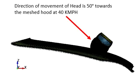
Initial Velocity applied = 40 KMPH in (X,-Z), at 50° angle
40 KMPH = 11.11 mm/ms
By using TRANSFORM command Headform was rotated
By 50° along Y direction.
Applied 11.11 mm/ms along Vector
VX = -7.1413746 mm/ms
VZ = -8.5107594 mm/ms
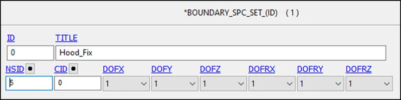
All DOFs fixed on the edges of hood

Output Requests -
Control termination – 10 ms
Output Requests –
Database > Binary D3PLOT at DT 0.5 ms
Database > ASCII option – GLSTAT, NODOUT AT DT= 0.5 ms
Energy Plots -
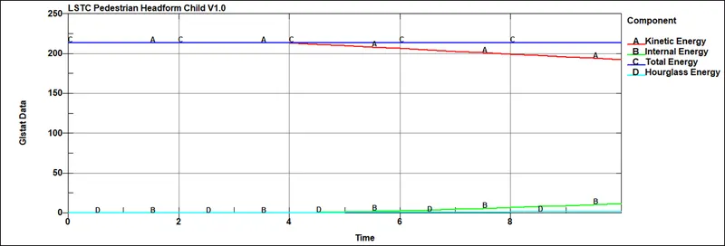
A certain drop in kinetic energy could be seen from the graph which is at the time of impact and it continues to decrease. So, this simulation could be considered for real life scenario.
Acceleration Plot -
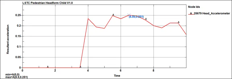
Max Acceleration at Head body after Impact = 0.251 mm/ms
HIC Plot -
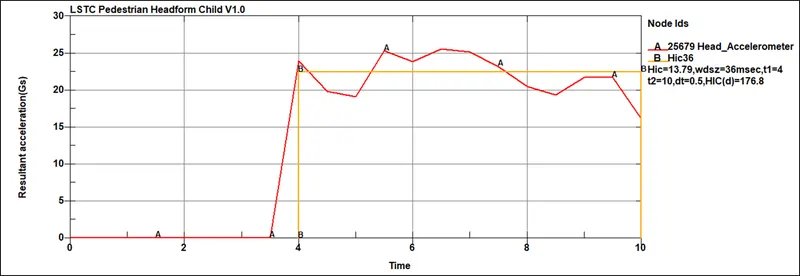
HIC = 13.79
HIC(d) = 176.8
Post Processing -
|
Case |
Stress on Headform (MPa) |
Resultant Acceleration (m/s) |
HIC |
HIC(d) |
|
Case 1 – Simple Head Impact on a Rigid Wall |
1816 |
68.9 |
2.055E+06 |
1.55E+06 |
|
Case 2 –Headform Impact on a Rigid Wall |
6.045 |
28.9 |
8.729E+04 |
6.602E+04 |
|
Case 3 – Headform Impact on a Meshed Hood |
3.779 |
6.47 |
13.79 |
176.8 |
Conclusion -
Case 3 - Headform Impact on a Meshed Hood represents real life scenario and based on the outputs.
HIC(d) = 176.8 <1000
As per FMVSS 201U . HIC(d) has to be limited to 1000.
So as per Case 3 , there should not be any fatal injuries.
HIC(d) represents the HIC value that a free motion headform would have measured if it were attached to a body. HIC(d) is used in FMVSS 201U because a free motion headform (not attached to a body) is used to impact the upper interior aspects of a vehicle. There is a difference in what a head form would measure if it were attached to a body vs if it is not attached (free motion); the HIC(d) calculation attempts to account for that difference. It provides an opportunity to conduct a test without needing to use the entire dummy.