Assignment 5-RADIOSS Interfaces & Study of Effect of Notches Challenge
Objective - To perform multiple cases by changing parameters/modify fe-modeling and observe change in contact energy and deformation pattern as well as perform meshing for bumper assembly.
Case setup -
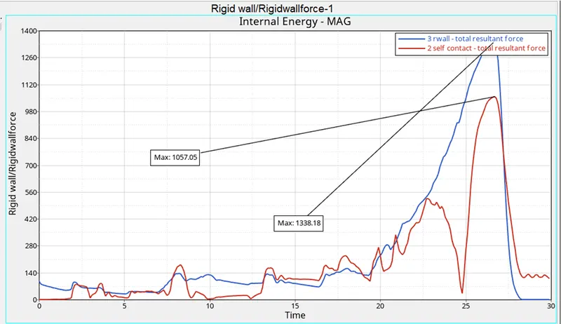
Case 1 - The model is run without any changes.
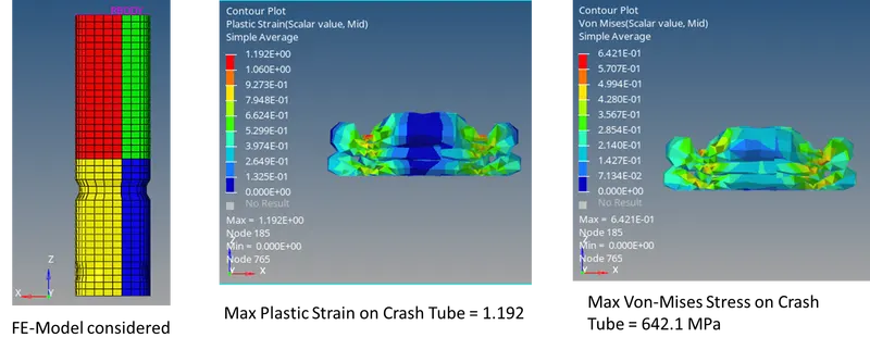
Case 2 - Case 1 hm file was taken and Inacti was changed to 6 and then model was run.
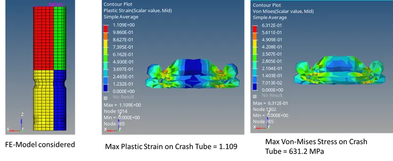
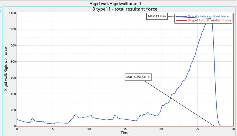
Case 3 - Case 1 hm file was taken and Type 7 contact interface was deleted and Type 11 contact Interface was created with recommended parameters.
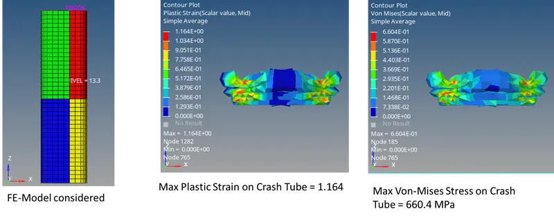
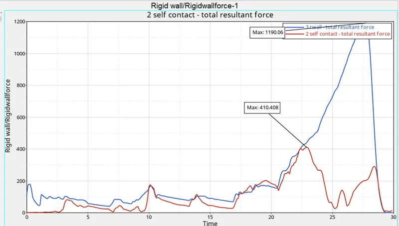
Case 4 - Case 2 hm file was taken and Both notches were removed. Mesh at locations of notches were deleted and straight mesh connecting nodes were recreated using ruled option in 2D mesh panel.
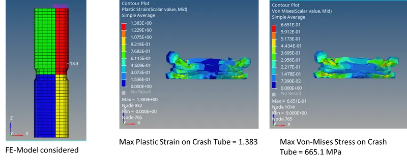
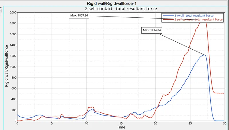
Case 5 - Case 2 hm file was taken and Both notches were removed. Mesh at locations of notches were deleted and notch was recreated using ruled option in 2D mesh panel.
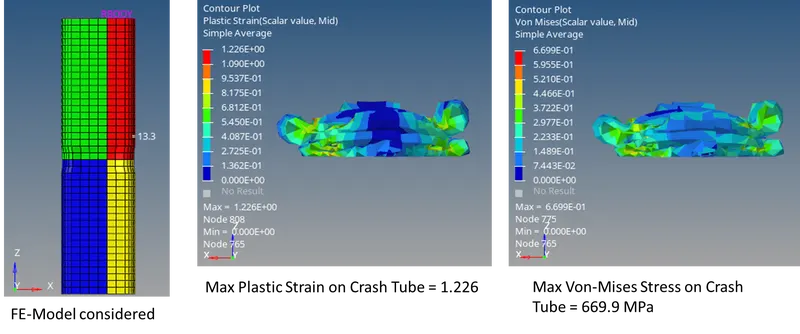
Case 6 - Case 2 hm file was taken and Both notches were removed. Mesh at locations of notches were deleted and notch was recreated using ruled option in 2D mesh panel at straight surface locations and fillet regions were ignored.
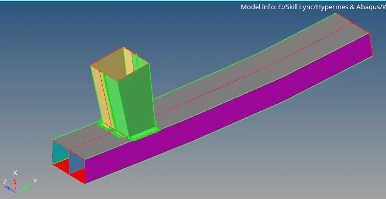
Bumper Meshing - A lot of free edges could be seen initally in the model. So 2 approaches could be followed, either geometry cleanup could be performed such that edges connect each other and mesh connectivity could be maintained throughout automatically or mesh could be created and connect via node merge option (F3) or by using equivalence (Shift+F3). The process followed here is by directly creating mesh first and then further connected via equivalence and at last spot welds have been created at locations mentioned using rigid elements.
Important Interface Parameters -
- Igap = Determines how size of gap is calculated. Based on inputs provided. It could be selected as constant throughout the analysis. Or can be kept variable and could be determined using Gapmin if Gapmin is not kept 0.
- Gapmin = It is the minimum gap for activation of interface. Generally it should be kept less than or equal to 0.5. Or if left default it would calculate based on thickness of slave and master surface in case of shell elements or choose 1/10th value of shortest edge of a brick element for solid mesh.
- Inacti = This should be turned on only if there are any penetrations in the model. Options can be chosen to fix the penetration automatically or remove stiffness on nodes for master/slave selections but that affects accuracy and hence is not recommended. Instead options like reduced gap or reduced gap + scaling could be used to get better accuracy and less convergence issue.
- Istf = Affects how stiffness of the interface is calculated. It uses scale factor Stfac value to calculate stiffness values based on material properties.
- Iform = Friction formulation can be chosen and required frictional coefficient could be entered.
- Stmin = It would be the minimum stiffness value that would be used for analysis. If Istf value obtained is less than Stmin value of Stmin would be considered for that interface.
- Idel = It determines what to do next with slave and master segments if elements fails/gets deleted that they are attached to. Option can be chosen to either remove all contact between master and slave node if element gets deleted or only that specific link to deleted element would be removed.
Comparison of all 6 cases based on errors and run time -
|
Case No |
Total No. of Cycles |
Energy Error (%) |
Mass Error |
Simulation Time (s) |
|
Case 1 –Original Model |
83469 |
-4.6% |
0 |
224.26 |
|
Case 2 – Inacti = 6 |
83469 |
-4.6% |
0 |
253.58 |
|
Case 3 – Type 11 Contact |
93695 |
-4.2% |
0 |
320.48 |
|
Case 4 – Removed Both Notches |
77586 |
-3.8% |
0 |
230.77 |
|
Case 5 – New Notch in Middle |
93058 |
-4.5% |
0 |
278.31 |
|
Case 6 – Notch with nodes from opposing faces |
70452 |
-4.5% |
0 |
223.42 |
Based on energy error – Ideally energy error should be close to 0%, but an error of up to -5% is acceptable.
Hence, it could be concluded parameters considered for above cases could represent realistic conditions.
Comparison of all 6 cases based on Stress and Strain
|
Case No |
Von Mises Stress (MPa) |
Max Plastic Strain |
|
Case 1 –Original Model |
695.3 |
1.192 |
|
Case 2 – Inacti = 6 |
642.1 |
1.192 |
|
Case 3 – Type 11 Contact |
631.2 |
1.109 |
|
Case 4 – Removed Both Notches |
660.4 |
1.164 |
|
Case 5 – New Notch in Middle |
665.1 |
1.383 |
|
Case 6 – Notch with nodes from opposing faces |
669.9 |
1.226 |
- Both Stress and Plastic strain is minimum for Case 3, i.e., by using Type 11 contact Interface.
- By changing value of inacti significant change has been observed in stress change but plastic strain remains same.
- Crush tube without any notches has plastic strain less than other cases with notches and type 7 contact interface.
Comparison of all 6 cases based on Forces and Energies
|
Case No |
Max Rigid Wall Forces (KN) |
Max Contact Forces (KN) |
Max Internal Energy (J) |
Max Kinetic Energy (J) |
|
Case 1 –Original Model |
1338.18 |
1057.05 |
42273 |
44400.8 |
|
Case 2 – Inacti = 6 |
1338.18 |
1057.05 |
42273 |
44400.8 |
|
Case 3 – Type 11 Contact |
1333.42 |
4.35133E-11 |
42429.2 |
44400.8 |
|
Case 4 – Removed Both Notches |
1190.06 |
410.408 |
42532.2 |
44386.9 |
|
Case 5 – New Notch in Middle |
1214.84 |
1857.84 |
42119 |
44386.9 |
|
Case 6 – Notch with nodes from opposing faces |
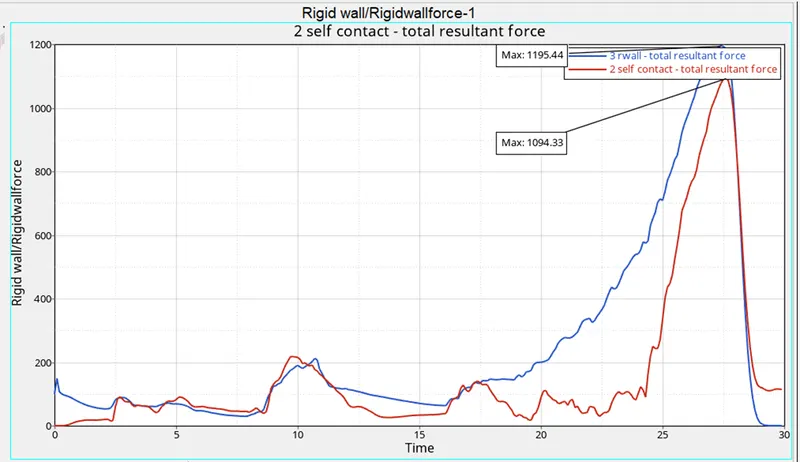
1195.44 |
1094.33 |
42048.7 |
44387.5 |
- Since no change in velocity was made Kinetic energy remains almost same. Due to change in mesh, there was slight change in mass of crash tube creating fluctuations in value of both Internal energy and Kinetic energy.
- Minimal energy is required to create contact interface by using Type 11 contact.
- For Case 4 with no notches contact energy required to create interface is much less compared to other cases with type 7 contact resulting in less rigid wall forces compared to other cases as well.
Case 01 – Original Model
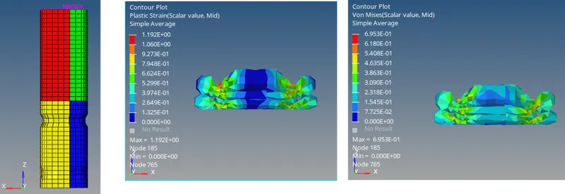

Case 02 – Inacti = 6
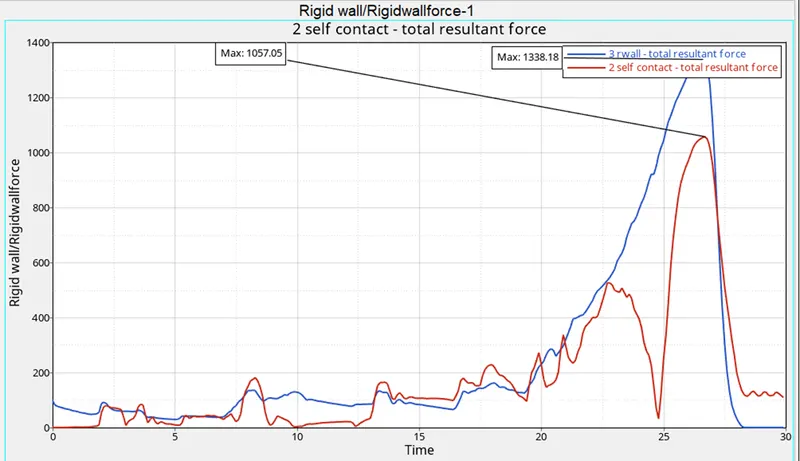
Case 03 – Type 11 Contact
Case 04 – Removed Both Notches
Case 05 – New Notch in Middle
Case 06– Notch with nodes from opposing faces