Assignment 6-Frontal Crash Simulation Challenge
Objective - To Perform Frontal Crash Simulation for Scaled Model and Extract Forces and Displacement at multiple locations.
Changes made to the model -
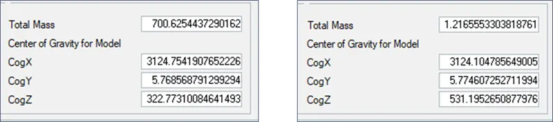
- Mass and COG Changes -
- Image 1 - Adjusted Mass and COG for simulation model as per 300K nodes ref model
- Image 2 - Original Model with 300K Nodes
- Unnecessary Interfaces were deleted and 1 Interface with Recommended Parameters was created to clear off Interferences and Penetrations.
- Initial Velocity was added to the system.
- Rigid wall with 0.1 frictional coefficient was created.
Mass and COG Changes -
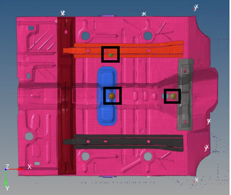
Mass Added to the Bottom Components (All Visible) = 39 Kgs
Mass added to the front (X Axis) = 446 Kgs
Mass added below Passenger seat compartment = 27.2 Kgs
Errors and Run Time -
|
Total No. of Cycles |
Energy Error (%) |
Mass Error (Kg) |
Simulation Time (s) |
|
80001 |
0.8% - -1.7% |
0.02984 |
4388.75 |
Units considered – Kg mm ms
Based on energy error – Ideally energy error should be close to 0%, but an error of 2% to -5% is acceptable.
Total mass of the system considered = 700.63 Kgs
Mass error %age = 0.004% which is in acceptable criteria
Hence, it could be concluded parameters considered for above cases could represent realistic conditions.
Important Interface Parameters -
- Igap = Determines how size of gap is calculated. Based on inputs provided. It could be selected as constant throughout the analysis. Or can be kept variable and could be determined using Gapmin if Gapmin is not kept 0.
- Gapmin = It is the minimum gap for activation of interface. Generally it should be kept less than or equal to 0.5. Or if left default it would calculate based on thickness of slave and master surface in case of shell elements or choose 1/10th value of shortest edge of a brick element for solid mesh.
- Inacti = This should be turned on only if there are any penetrations in the model. Options can be chosen to fix the penetration automatically or remove stiffness on nodes for master/slave selections but that affects accuracy and hence is not recommended. Instead options like reduced gap or reduced gap + scaling could be used to get better accuracy and less convergence issue.
- Istf = Affects how stiffness of the interface is calculated. It uses scale factor Stfac value to calculate stiffness values based on material properties.
- Iform = Friction formulation can be chosen and required frictional coefficient could be entered.
- Stmin = It would be the minimum stiffness value that would be used for analysis. If Istf value obtained is less than Stmin value of Stmin would be considered for that interface.
- Idel = It determines what to do next with slave and master segments if elements fails/gets deleted that they are attached to. Option can be chosen to either remove all contact between master and slave node if element gets deleted or only that specific link to deleted element would be removed.
Forces and Energies -
|
Max Rigid Wall Forces (KN) |
Max Contact Forces (KN) |
Max Internal Energy (J) |
Max Kinetic Energy (J) |
Hourglass Energy (J) |
|
141.299 |
1865.38 |
47365.5 |
87917.4 |
465.773 |
Total mass of the system considered = 700.6254437290162 Kgs
KE = 1/2 mv^2 = 1/2 "700.6254437290162" 〖(15.6464)〗^2 = 85,759.9989 J
Since we have seen positive energy error that means some energy was added to the system and hence there is slight increase in Kinetic Energy.
Kinetic and Internal Energy -
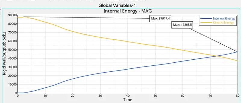
From the graph it could be seen that if model could be run for some more time we can see almost all of Kinetic Energy getting converted to Internal Energy.
Contact Forces and Hourglass Energy -
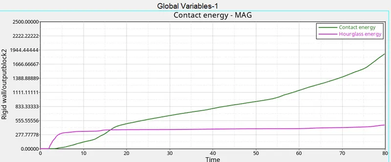
Hourglass energy remains almost contact throughout. That explains some energy is constantly provided throughout the run to maintain stability.
Interface Forces -
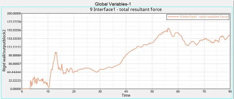
With recommended parameters it could be seen penetrations were taken care of (if any) and contact force kept on increasing post crash as most front components clustered.
Rigid Wall Forces -
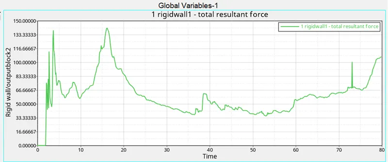
As Components approached wall spikes could be seen at contact b/w BIW and wall. Within first 30 ms all the front components(bumpers and cross sections) were already in contact with the wall. Due to center void in model not much wall force could be seen during 30 ms – 60 ms
Sectional Forces on rail -
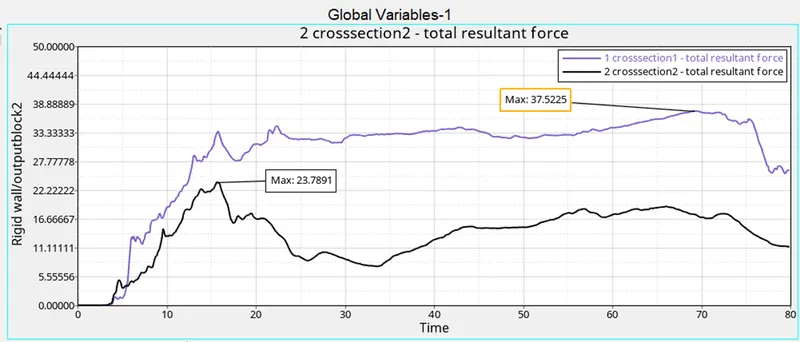
Maximum Resultant Sectional Force on rail at Driver’s end – 23.7891 KN
Maximum Resultant Sectional Force on rail at Passenger’s end – 37.5225 KN
Sectional Forces on Shotgun -
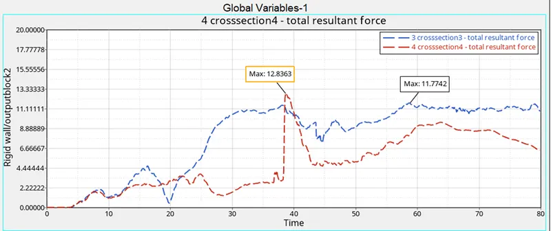
Maximum Resultant Sectional Force on Shotgun at Driver’s end – 12.8363 KN
Maximum Resultant Sectional Force on Shotgun at Passenger’s end – 11.7742 KN
Sectional Forces on Hinge Pillar -
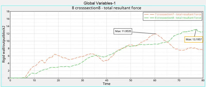
Maximum Resultant Sectional Force on Hinge Pillar at Driver’s end – 11.9535 KN
Maximum Resultant Sectional Force on Hinge Pillar at Passenger’s end – 13.1957 KN
Sectional Forces on A Pillar -
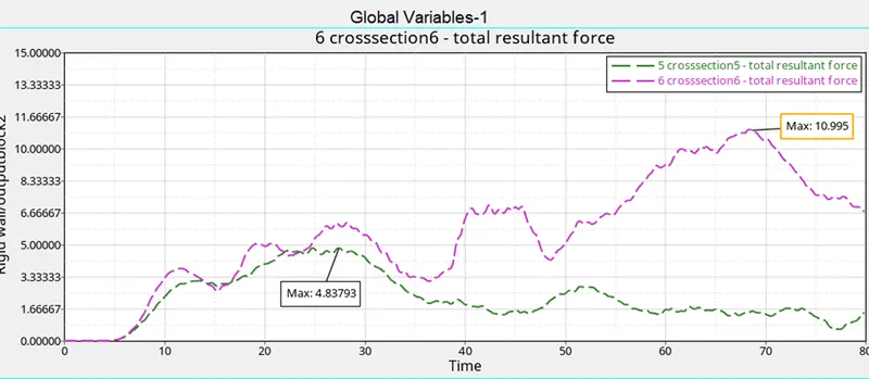
Maximum Resultant Sectional Force on A Pillar at Driver’s end – 10.995 KN
Maximum Resultant Sectional Force on A Pillar at Passenger’s end – 4.83793 KN
Acceleration at bottom of B-Pillar -
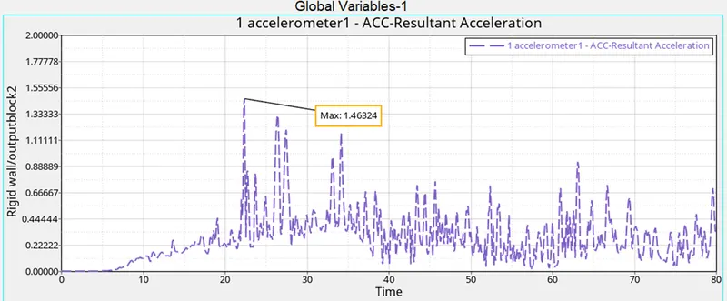
From the animation plots we could see there wasn’t much movement upto 20 ms so there is not much change in the graph also. Due to sudden change peak is observed just after 20 ms. Max Resultant acceleration observed is 1.46324 mm/ms2
Intrusion on Dash Wall on Node - 66695 -
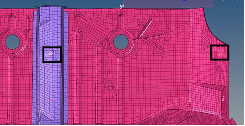
Before Crash distance b/w Dash wall node and Ref node – 799.252 mm
Post crash distance – 176.488 mm
Intrusion on Dash Wall on Node - 66244 -
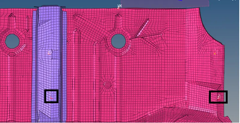
Before Crash distance b/w Dash wall node and Ref node – 806.115 mm
Post crash distance – 83.68 mm