Week - 4 - Crash Box Simulation
Objective - To perform simulation of a crash box moving horizontally with a speed of 50 Kmph and crashing against a wall and check its deformation behaviour and evaluate energy and forces.
Geometry Details -
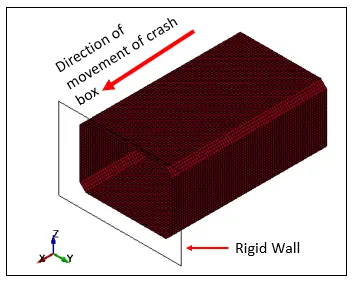
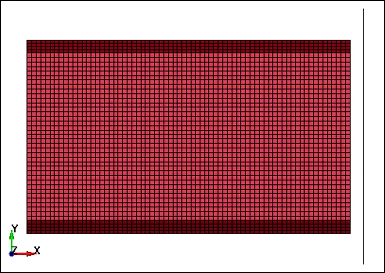
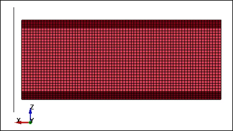
CASE – 1 Crash Box Thickness = 1.2 mm
Case Setup -
Units System considered – gm-mm-ms
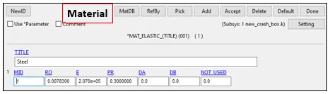
Elastic Steel material with properties –
RO = 0.007830 gm/mm3
E = 2.07E+05 gm/mm-ms2
PR = 0.3
Section –
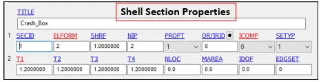
Shell Properties with ELFORM=2(default) and thickness = 1.2 mm
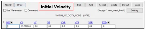
Initial velocity applied in +X direction = 13.8889 mm/ms (50 Kmph)
Output Requests -
Control termination – 1.5 ms
Output Requests –
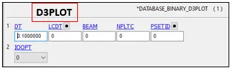
Database > Binary D3PLOT at DT 0.1 ms
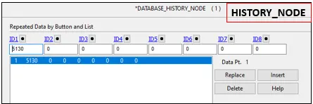
Database > HISTORY_NODE (Central node for accelerometer reading)
Database > ASCII_option – GLSTAT, NODOUT, RWFORC AT DT= 0.1 ms

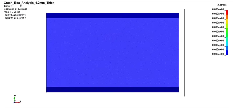
Animation - X Direction Stress Plolt (MPa)
Max stress = 204.531 MPa acting on the Crash Box which is less than yield limit of the material = 250 MPa, hence no Strain developed and the crash box bounces back after colliding with the wall.
Result Plots -
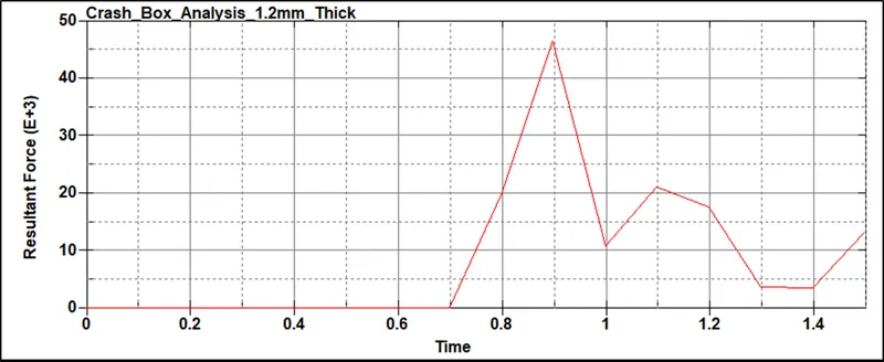
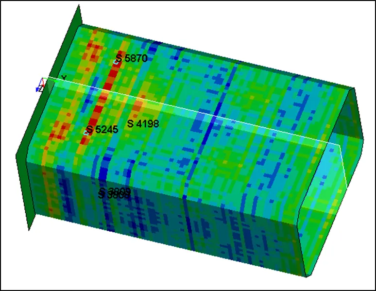
Section considered along the length.
Max Force = 46500 gm-mm/ms2 @ 0.9 ms
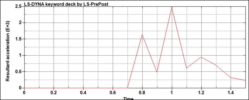
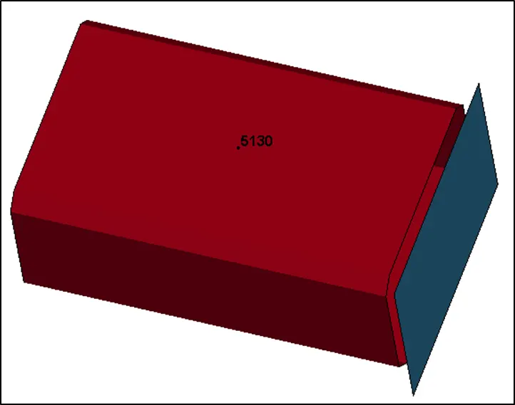
Acceleartion on Node at center of the crash Box along the length -
Node considered along the length.
Max Acceleration = 2470 mm/ms2 @ 1 ms
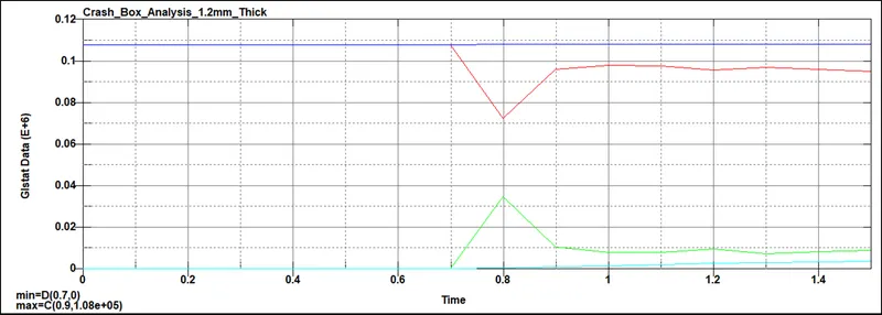
Energy Plots -
Mass = 1120 gm,
Velocity = 13.8889 mm/ms
Kinetic Energy = 0.5*m*v*v = 0.5*1120*13.8889*13.8889 = 1,08,024.8641976 gm-mm2/ms2
Kinetic Energy obtained via calculation is in the same range of what is obtained from analysis. Hence output obtained could depict real life scenario.
CASE – 2 Crash Box Thickness = 1.5 mm
Case Setup -
Units System considered – gm-mm-ms
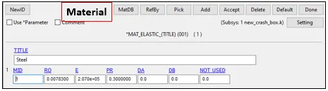
Elastic Steel material with properties –
RO = 0.007830 gm/mm3
E = 2.07E+05 gm/mm-ms2
PR = 0.3
Section –
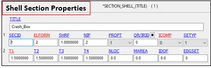
Shell Properties with ELFORM=2(default) and thickness = 1.2 mm
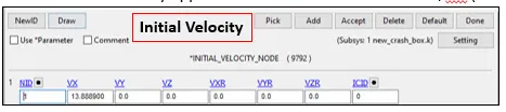
Initial velocity applied in +X direction = 13.8889 mm/ms (50 Kmph)
Output Requests -
Control termination – 1.5 ms
Output Requests –
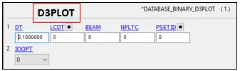
Database > Binary D3PLOT at DT 0.1 ms
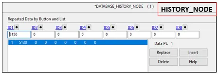
Database > HISTORY_NODE (Central node for accelerometer reading)
Database > ASCII_option – GLSTAT, NODOUT, RWFORC AT DT= 0.1 ms

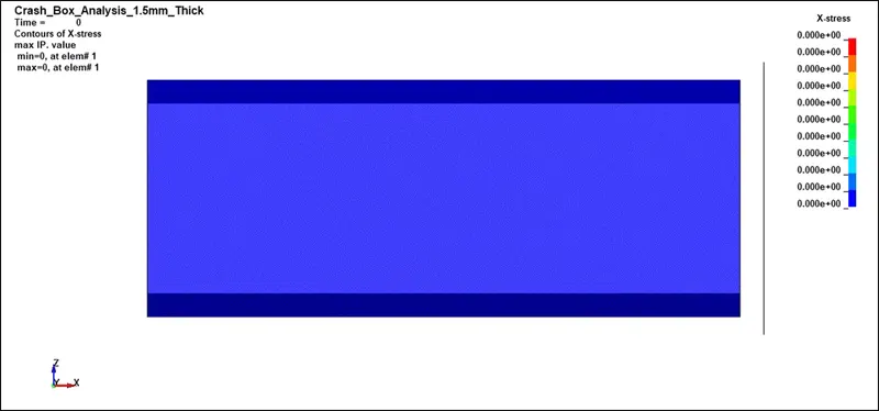
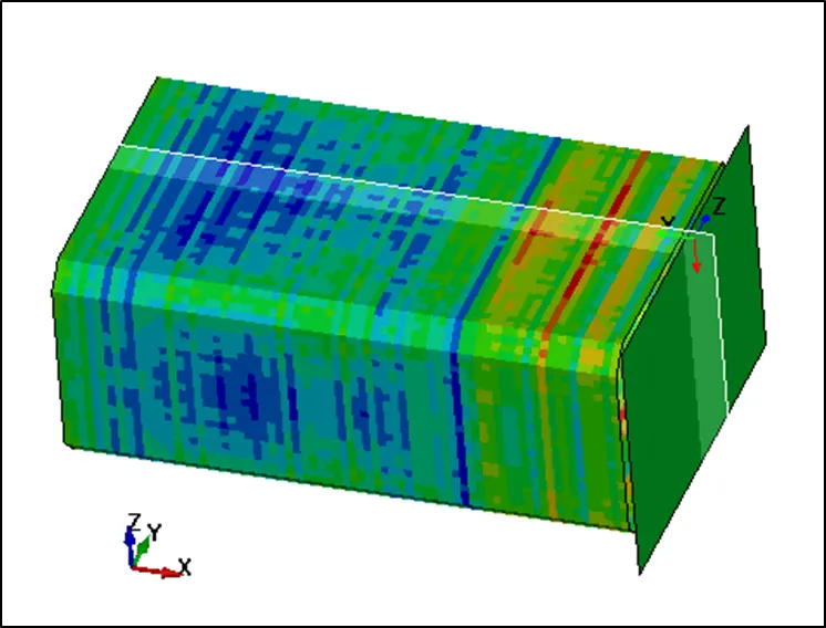
Animation - X Direction Stress Plot (MPa)
Max stress = 239.343 MPa acting on the Crash Box which is less than yield limit of the material = 250 MPa, hence
No Strain developed and the crash box bounces back after colliding with the wall.
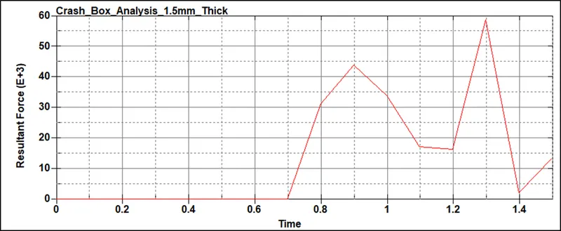
Sectional Force -
Section considered along the length.
Max Force = 58700 gm-mm/ms2 @ 1.3 ms
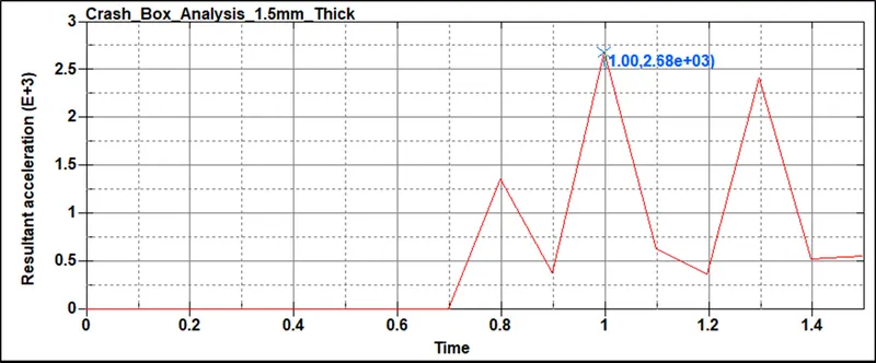
Acceleartion on Node at center of the crash Box along the length -
Node considered along the length.
Max Acceleration = 2580 mm/ms2 @ 1 ms
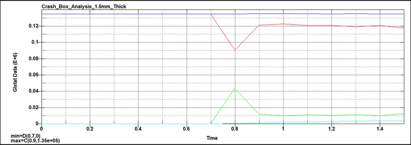
Energy Plots -
Mass = 1400 gm,
Velocity = 13.8889 mm/ms
Kinetic Energy = 0.5*m*v*v = 0.5*1400*13.8889*13.8889 = 1,35,031.080247 gm-mm2/ms2
Kinetic Energy obtained via calculation is in the same range of what is obtained from analysis. Hence output obtained could depict real life scenario.
Conclusion -
|
Case 1 – Crash Box Thickness = 1.2 mm |
Case 2 – Crash Box Thickness = 1.5 mm |
|
Mass = 1120 gm |
Mass = 1400 gm |
|
Velocity = 13.8889 mm/ms |
Velocity = 13.8889 mm/ms |
|
Kinetic Energy = 1,08,024.8641976 gm-mm2/ms2 |
Kinetic Energy = 1,35,031.080247 gm-mm2/ms2 |
|
Acceleration at Node 5130 = 2470 mm/ms2 |
Acceleration at Node 5130 = 2580 mm/ms2 |
|
Sectional Force = 58700 gm-mm/ms2 |
Sectional Force = 46500 gm-mm/ms2 |
|
X Direction Stress = 204.531 MPa |
X Direction Stress = 239.343 MPa |
From the above table it could be concluded that due to increase in thickness volume and mass increased,
Which resulted in increase of acceleration and forces.
Stress has also increased due to increase in force along the length.