Week - 3 Drop test Challenge
Objective - To perform a Drop Test of a phone and check how the impact effects the overall design and if stresses are within limits.
Changes made to the model -
- Unit system followed - tonne mm s
- Solid elements created for Ground deleted instead of shell elements to keep less node count.
- Shell and Solid sections with ELFORM=2 were created and assigned to respective bodies. Also a thickness of 2 mm was assigned to Ground shell elements.
- MAT20 (Rigid) is used for Ground with properties of Steel and was assigned to Part.
- MAT24(Piecewise Linear Plasticity) material is used for Phone with properties of steel and was assigned to Part.
- Contact Interface was created b/w Phone and Ground –Automatic Surface to Surface with friction coefficient as 0.2 and Slave nodes were selected for Phone and Master Nodes were selected for Ground.
- Initial Velocity is created and all nodes of phone is selected and value of gravity is given.
- SPC set is created to constrain boundary nodes of Ground in all DOFs.
- Control Termination card is created and an end time of 4 ms is given.
- Outputs requested – Binary_D3Plot, Under ASCII GLSTAT,MATSUM,NODOUT is requested at every 0.2 ms.
- Run results -
Total No. of Cycles
Simulation Time (s)
8311
10
Von-Mises Stress Plot (MPa) - 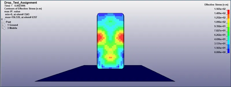
Max Von-Mises stress = 156.539 MPa observed at side edges of the Phone after impact.
Total, Internal & Kinetic Energy -
|
Max Total Energy (J) |
Max Internal Energy (J) |
Max Kinetic Energy (J) |
|
41.8 |
41.5 |
30.5 |
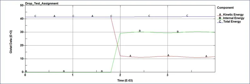
- Change in Kinetic Energy is observed as soon as the phone touches the ground. After impact there is a change in velocity and hence the curve shows a steep decline.
- If the analysis continues for some more time whole of Kinetic energy would convert to Internal Energy.
Conclusion -
- Since Yield limit of material considered is 250 MPa and max Von-Mises stress observed is lesser than that it could be concluded that the phone could survive such a fall for the given material.