Week - 5 - Modelling Spotwelds
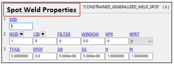
Objective - To perform a crash test b/w to components connected with 6 spot welds modeled as both beams and solid elements and check the differences in parameters w.r.t. change in modeling approach.
CASE – 1
Spot Welds modelled as Beams
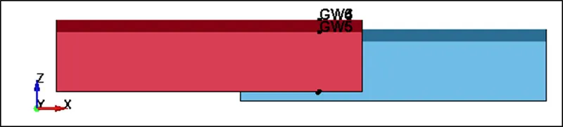
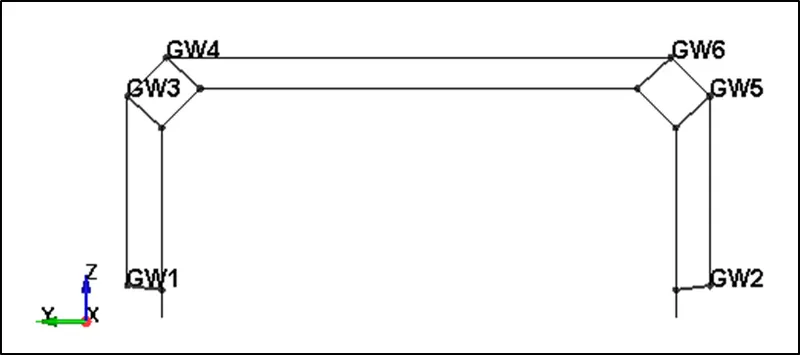
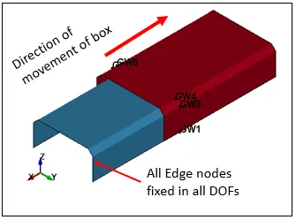
Model considered for analysis -
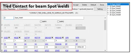
Shell elements for Crash Box and Beam elements for Spot Welds
Case Setup -
Units System considered – gm-mm-ms
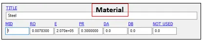
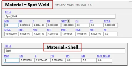
Elastic Steel material with properties –
RO = 0.007830 gm/mm3
E = 2.07E+05 gm/mm-ms2
PR = 0.3
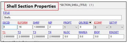
Section –
Shell Properties with ELFORM=16(Fully Integrated)
and thickness = 2 mm
Boundary Conditions -
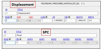
Units System considered – gm-mm-ms
Displacement applied in -X
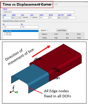
Output Requests -
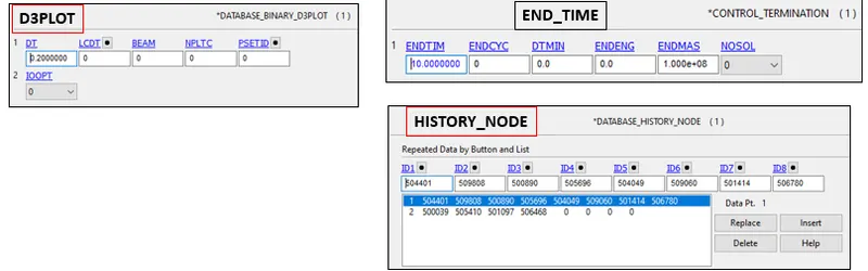
Control termination – 10 ms
Output Requests –
Database > Binary D3PLOT at DT 0.2 ms
Database > HISTORY_NODE (Spot Weld Nodes)
Database > ASCII option – GLSTAT, SWFORC AT DT= 0.2 ms
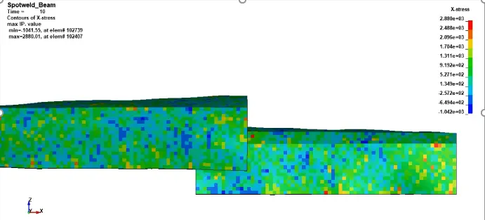
X Direction Stress Plots (MPa) -
Max stress = 24165.7 MPa acting on the Crash Box.
There is a steep increment in stresses as soon as spot weld elements gets deleted
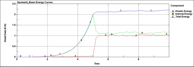
Energy Plots -
From the above graph it could be seen that all of the Internal Energy is getting converted into Kinetic Energy and if the simulation would have run for a longer time period both points would meet and continue as a straight line.
Max Kinetic Energy = 1100000 N-mm
Result Plots -
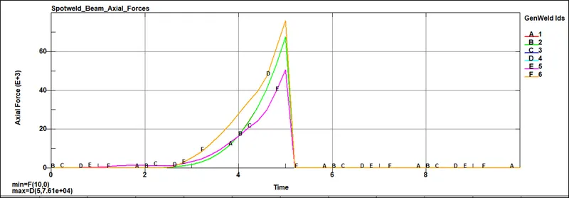
Since welds are created symmetrically Axial forces are same for welds on similar locations.
Max Axial Force = 76100 N
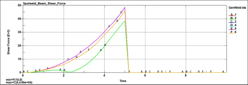
Since welds are created symmetrically Shear forces are same for welds on similar locations.
Max Shear Force = 48600 N
CASE – 2
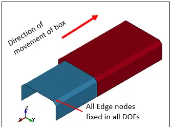
Spot Welds modelled as Solid Elements
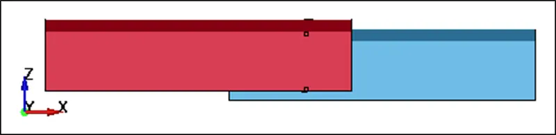
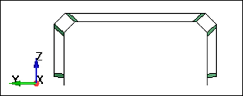
Model considered for analysis -
Shell elements for Crash Box and
Solid elements for Spot Welds
Case Setup -
Units System considered – gm-mm-ms
Elastic Steel material with properties –
RO = 0.007830 gm/mm3
E = 2.07E+05 gm/mm-ms2
PR = 0.3
Section –
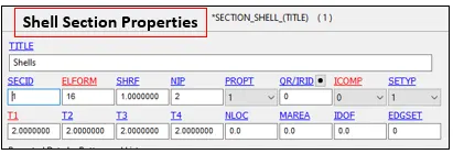
Shell Properties with ELFORM=16(Fully Integrated) and
thickness = 2 mm
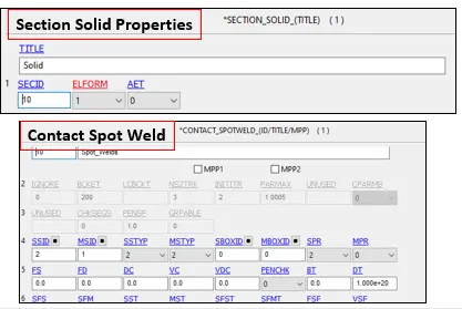
Section Solid with ELFORM = 1 for Spot Welds
Boundary Conditions -
Units System considered – gm-mm-ms
Displacement applied in -X
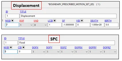
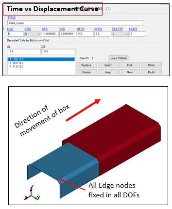
Output Requests -
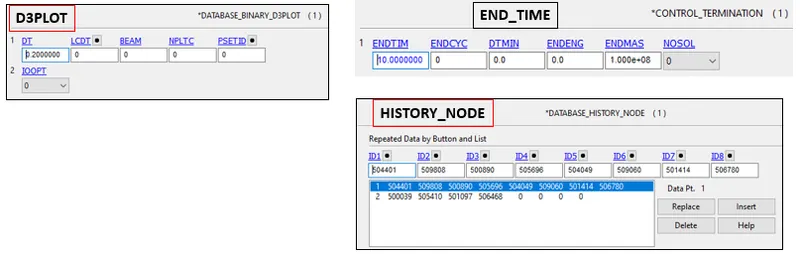
Control termination – 10 ms
Output Requests –
Database > Binary D3PLOT at DT 0.2 ms
Database > HISTORY_NODE (Spot Weld Nodes)
Database > ASCII option – GLSTAT, SWFORC AT DT= 0.2 ms
X Direction Stress Plots (MPa) -
Max stress = 2342.11 MPa acting on the Crash Box
There is a steep increment in stresses as soon as spot weld elements gets deleted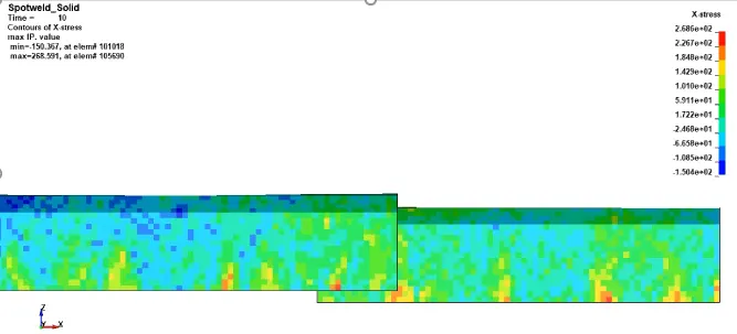
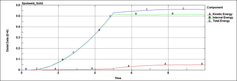
Energy Plots -
From the above graph it could be seen that all of the Internal Energy is getting converted into Kinetic Energy and if the simulation would have run for a longer time period both points would meet and continue as a straight line.
Max Kinetic Energy = 48600 N-mm
Result Plots -
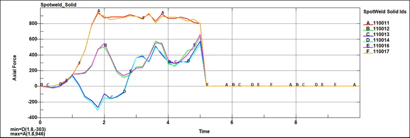
Since welds are created symmetrically Axial forces are similar for welds on similar locations.
Max Axial Force = 946 N
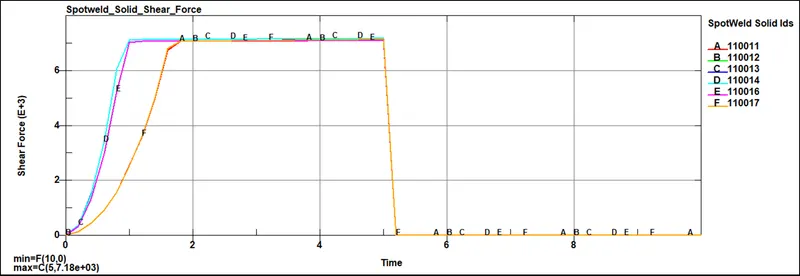
Since welds are created symmetrically Shear forces are same for welds on similar locations.
Max Shear Force = 7180 N
Conclusion -
|
Case 1 – Beam Elements Spot Weld |
Case 2 – Solid Elements Spot Welds |
|
Spot Weld Element Deletion Time = 5 ms |
Spot Weld Element Deletion Time = 5 ms |
|
Kinetic Energy = 1100000 N-mm |
Kinetic Energy = 48600 N-mm |
|
X Direction Stress = 24165.7 MPa |
X Direction Stress = 2342.11 MPa |
|
Max Axial Force = 76100 N |
Max Axial Force = 946 N |
|
Max Shear Force =48600 N |
Max Shear Force = 7180 N |
From the above table it could be concluded that Axial and Shear forces required for failure of beam element spot welds is much higher compared to solid elements it could withstand high impacts but at the same time could also transfer load and high stresses to the parent components which ideally wouldn’t be acceptable.