Week 6 Challenge
AIM: The Aim of this challenge is to understand about the bridges which carry pipes alone. This type of bridges are mainly constructed as part of wate supply system, be it a part of irrigation project or water treatment plan or sewage treatment plants.
Here, in the challenge it is particularly memtioned about DI pipes- ductile Iron pipes, these are specialized pipes used in supplying water. There are different class in the material used in the manufacturing of these pipes. In DI partcularly has class K7, k9 are mentioned.
Introduction: The challenge is to calculate the load due to the pipe material and the water load. Then apply these loads in the staddd model and analyse the super structure for these loads alone.
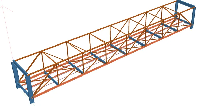
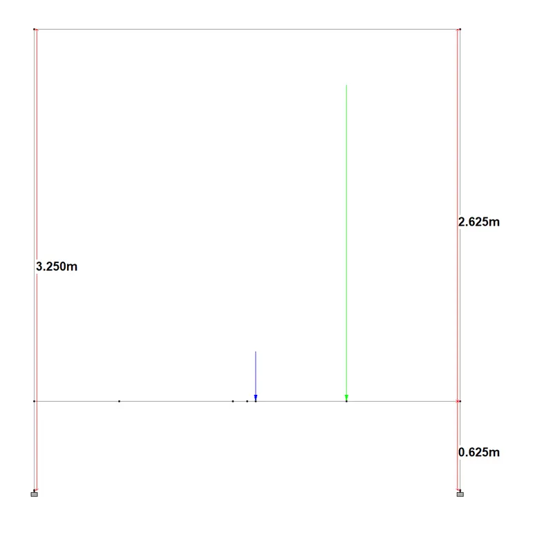
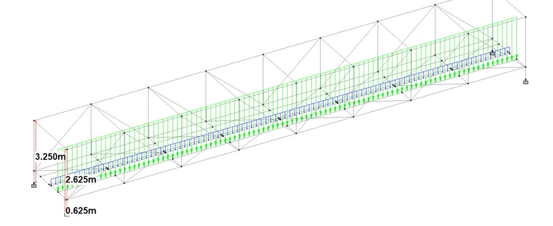
THe bridge super structure is build with steel structures. The sub structure is concrete. Here since only the super structure is modelled and loads are applied on the super structure by running a dummy member through the span. Since there are two pipes two dummy members are run through the span. A very light weight tube member is considered as the dummy member.
The pipe loads are divided into two categories- self weightof pipe + water load in the pipe.
Procedure:
Calculations of loads on the super structure due to pipie weight and water load in the pipe:
From the web page
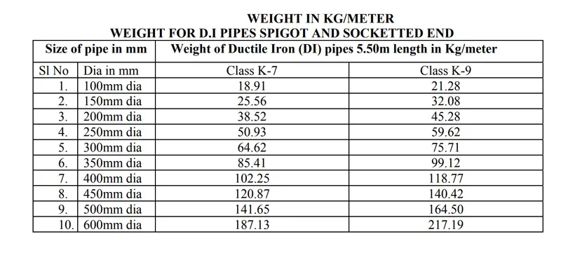
Assuming Class-K7
Pipe Dia -1- 700 dia NB DI pipe taking for 700 mm dia unit weight as 245 kg/m
Pipe Dia-2- 200 dia NB DI pipe - for 200 dia fom the above table- 38.52kg/m
Span length: 24-m
Self weight calculations
The total weight of the 200 dia pipe = 38.52x 24=924.49kg
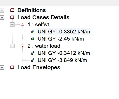
The UDL will be the same =924.49/24= 38.52 kg/m= 385.2 N/m = 0.3852kN/m
The total weight of the 700mm dia = 245 kg/m = 2450N/m= 2.45kN/m
Water load calculations
C/S Area of the pipe multiplied by unit weight of water
Pi/4 x dia^2 x 10
for 200 mm dia- (3.142/4) x 0.2^2 x 10 = 0.03412 x 10 = 0.3412kN/m
for 700 mm dia - (3.142/4) x 0.7^2 x 10 =0.3849 x 10 = 3.849 kN/m
Stadd model
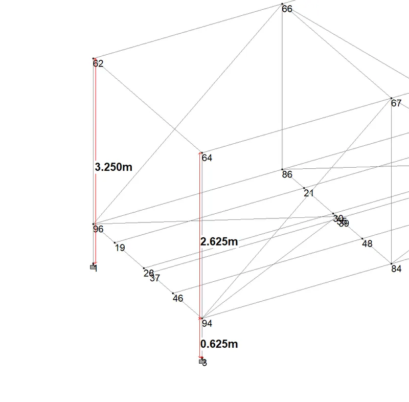
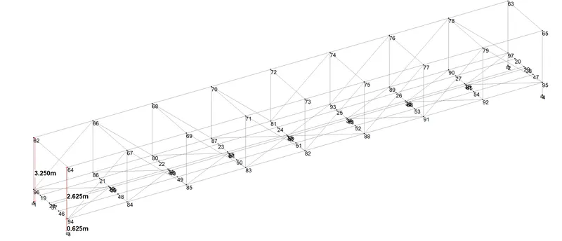
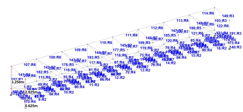
Beam Lable
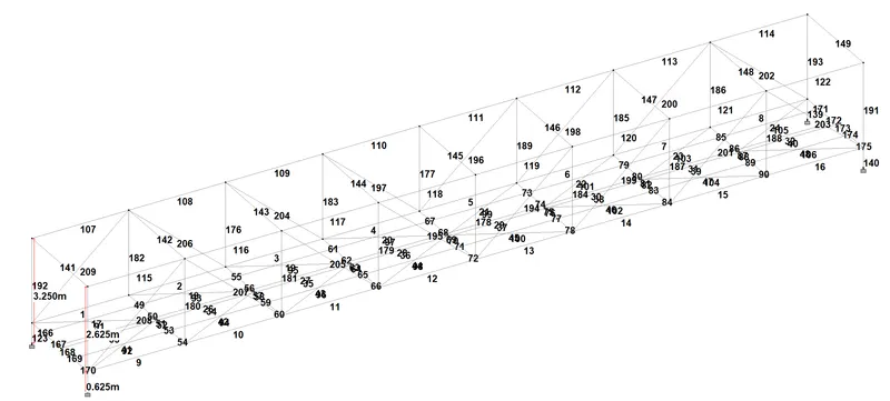
Supports
Fixed supports are given at four nodes.
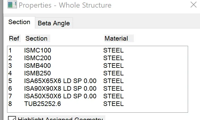
Properties of the members
Loading ( The model dimensions are also shown)
Results
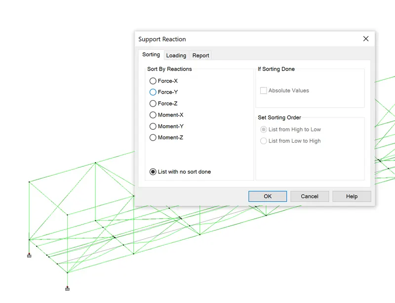
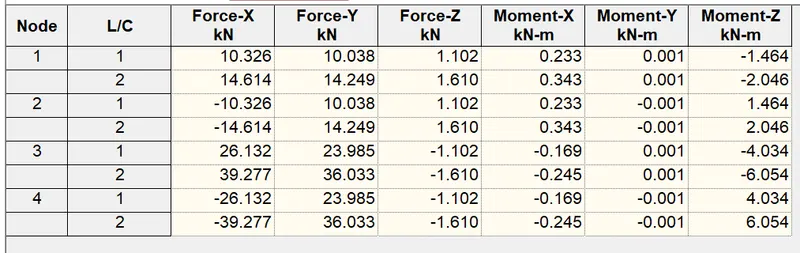
Reactions
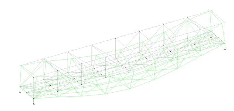
Deflection Pattern due to selfweight of the water pipe.
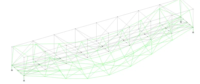
Deflection Pattern due to water in the water pipe.
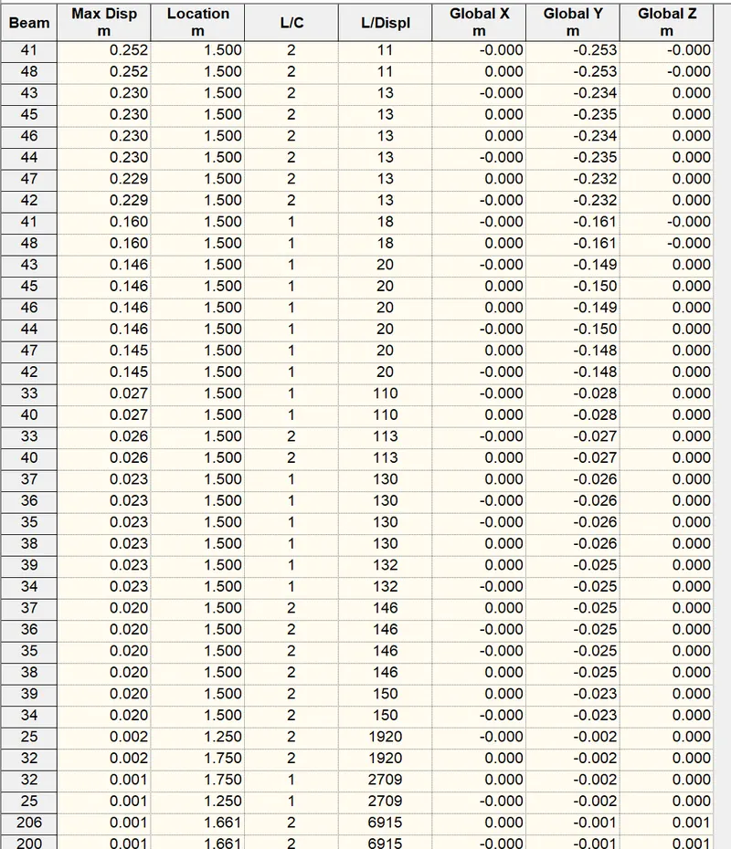
Section displacements (few examples are shown)
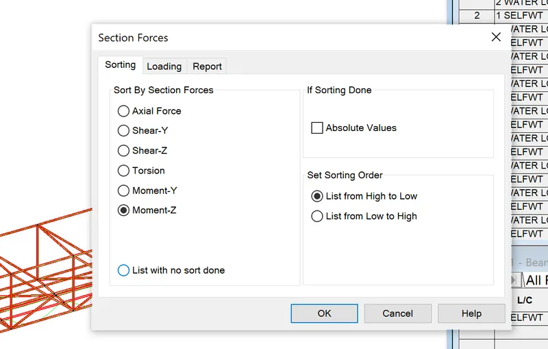
Moment - MZ (few members with both the load case are shown)
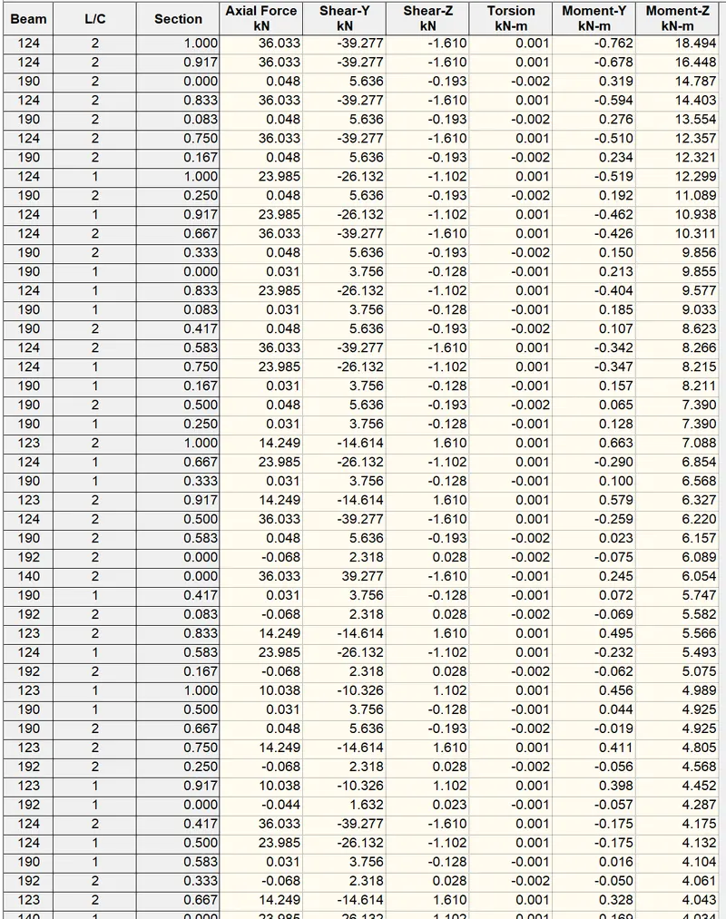
Like wise MY values can also be obtained
Shear force Fy
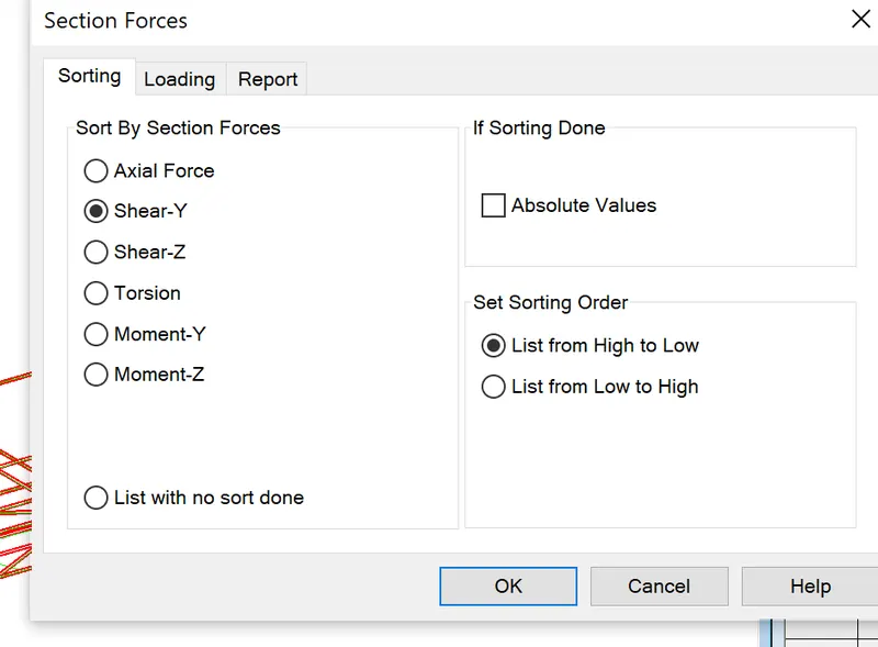
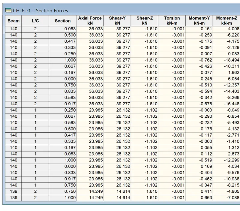
Beam 140 has more shear from the results and the values are tabulted.
The beam 140 is the vertical member right above the support.
The following is the bending moment diagram due to water load alone
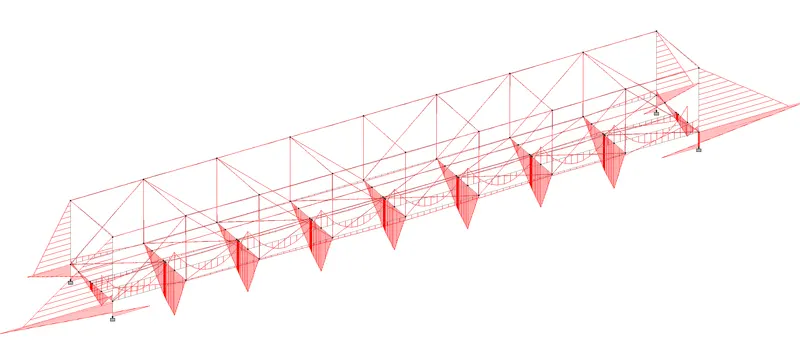
The following is the bending moment due to self weight of the water pipe alone
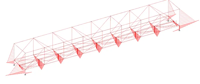
The bending moment diagram at the end and immediate frame
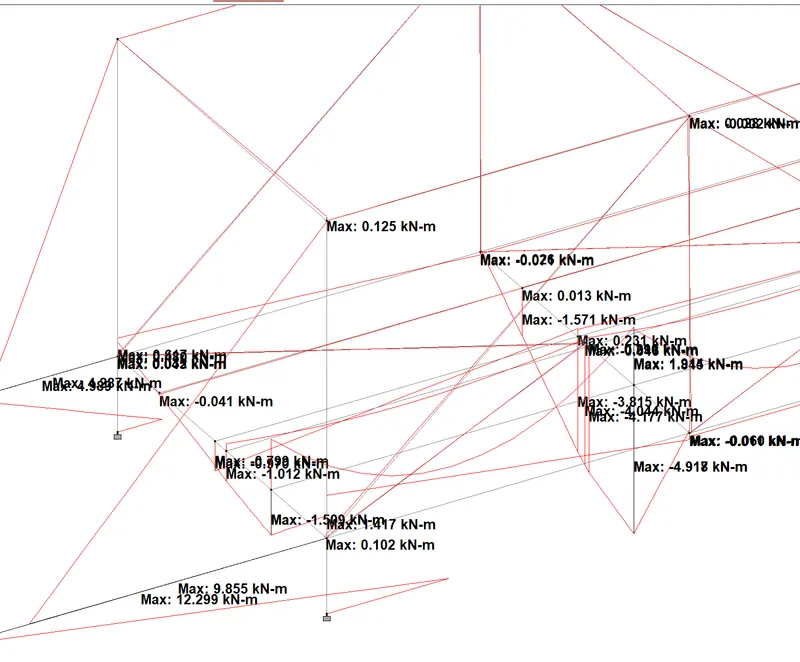
Similarly shear values in FY, Fx etc can be obtained.
Conclusion: The above analysis shows the right behaviour of the structure due to applied loads hence structure can be further checked for the design and also the steel bridge needs the joint design. which can also be carried with the help of axial forces and the bending moments in the members.