Creating Kitchen layout, Hatching of Architectural elements and sectional view of an Industrial Building in AutoCad
AIM: The aim of this challenge is to learn about different hatch patterns, their scaling to suit the appearence.
The aim of this particular question is to choose the kitchen architectural drawing and show the differnt hatch patterns on it.
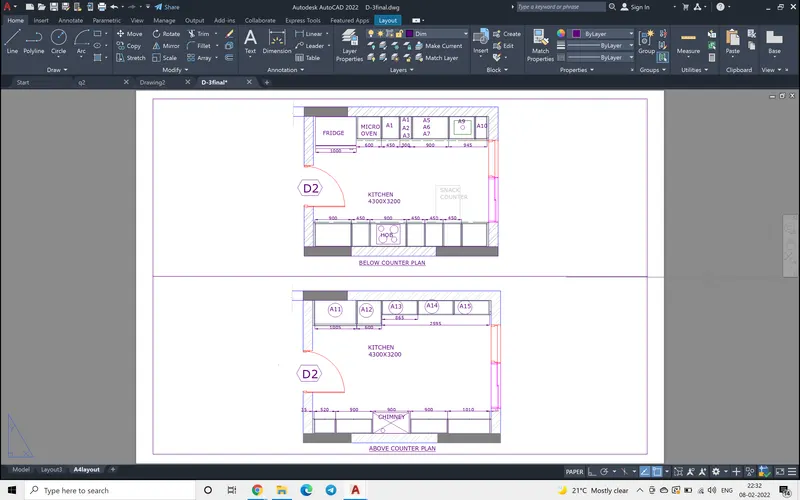
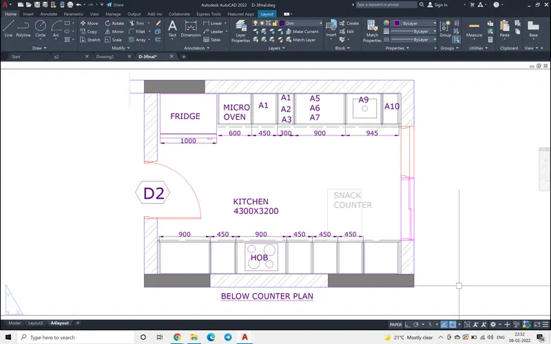
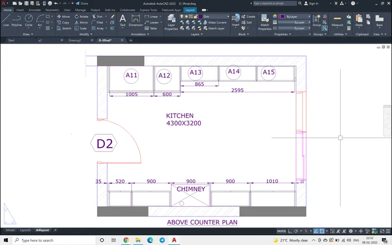
INTRODUCTION: The hatch pattern gives the information like, whether the drawing is section or elevation. the following drawing id the sectional plan of kitchen below the counter and above the counter.
PROCEDURE:
Step-1
At the command prompt layer command is used,
a new layer named hatch with grey colour is selected.
keeping hatch as current layer,
Step-2
At command line choosing the command Hatch,
and the command ribbon appears, in that we can choose any of the patterns, which are predefined.
here for example we used solid fill, then the option select the object or pick a point comes, by default it will be pick a point.
Step-3
When we pick a point, if the area we picked is not closed boundary, then the hatch cannot happen, the information pops like the area is not a closed figure. we can check and select a closed area.
Even after we select some times the hatch will be so closely placed that the pattern we chose other than solid fill also look like solid fill therefore we have to change the scale of the hatch.
At the command prompt select the objects and use propeties command CH, there we can change the scale of the hatch, or in the hatch ribbon we can change. higher the number of the scale the visibility of the pattern will be clear, if the number is put in excess then the hatch will not appear on the drawing.
Sometimes , for example for concrete hatching if the area to be filled is very small and slender the scale need to be given in fractions. the hatch pattern and its scale depends on the size of the are to be filled.
keeping in view all the above tips, the following hatch patten is achieved.
****************************************************************************************************************
AIM:The aim here is to show the hatch patterns of the elevation drawings.
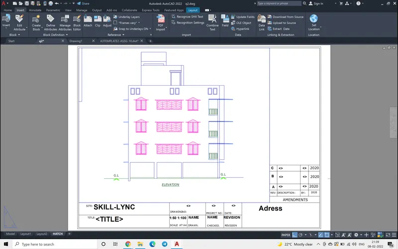
INTRODUCTION: The following elevation wa chosen, the glass is predefined in the hatch patterns of autocad.
PROCEDURE:
Step-1
at command prompt Layer was used and a separate layer was created for window and itss hatch pattern.
Step-2
The window glass panes were selected and hatch patterns was entered.
the hatch pattern was so close that it looked like solid fill,
Step-3
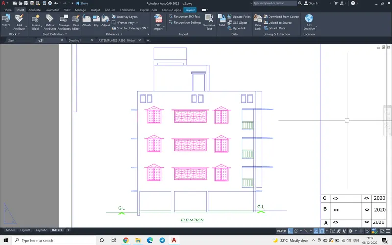
The hatch pattern was selected and properties command CH or Ctrl 1 was chose and the scale was changed to 10.
Step-4
After changing the scale the hatch would like the image below..
Step-5
One of the window has different pattern,
The window was first divided as show in given image by giving divide command, and small rctangular blocks inside the window were created and the ziz zag lines were drawn.
Step-6
at the command prompt line command was used to draw the pattern.
The following drawing is achieved
****************************************************************************************************************
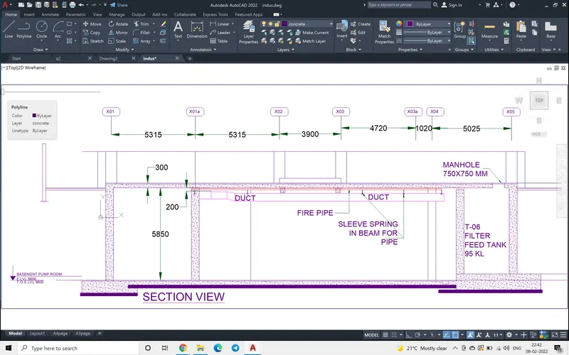
AIM: To draw the industrial basement as shown below and giving the concrete hatch and soli fil hatch. Here the area to be filled is very slender, the hatch pattern scaling has to be given proportionatly
INTRODUCTION: Any drawing, there are many interesting entities are drawn to high light the details. Hatch is one of the entity, which shows whether the drawing is a plan or elevation. An elevation hatch always has a peculiar patterns. For example when a concret wall is cut the appearence of concrete can be clearly seen so is the hatch pattern on the drawing indicates.
Even when a brick masonry is cut the particaluar hatch pattern is predefined in engineering drawing and the same is followed here in autocad also.
PROCEDURE
Step -1:
At the command prompt, using command layer
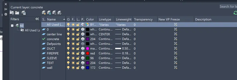
different new layers were created. The following image show the number of layer used.
Step-2
at th command prompt keeping center line as curernt layer, the centre line were drawn first.
Step-3
at the command prompt keeping wall as current layer, the above groung drawing was finsihed first.
Step-4
keeping the concrete as current layer below the groung structure was drawn
Step-5
Keeping the duct as current layer the duct is drawn
Step-6
keeping the current layer as sleeve, the sleeve was drawn
Step-7
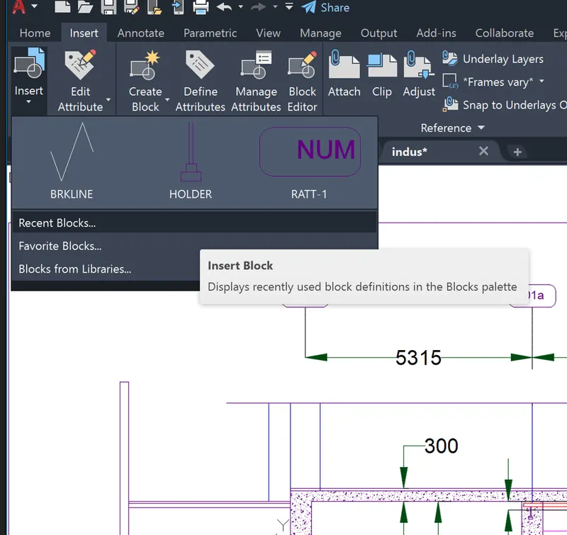
at the command prompt block command was used and the sleeve was conveted to block, the block name was given as holder.
Step-8
using insert command this bock was pasted wereever required as shown in the drawing.
Step -9:Hatch command was used
the catch pattern concrete was selected.
Then the area was picked, the hatch appeared to be like solid fill then
Step -10
the hatch pattern was selected CH command was given
then the scale was changed to 10, the patten was neatly appering at this scale.
Step -11
Dimlinear command was used to annototate the dimension.
dimstyle was used to change the arrow size and text height to suit the drawing.
Step -12
Mtext command was used to write the text
Step -13
where ever arrow to be used, command QL was used.
The following drawing was achieved.