Creating various 3D Models like Furniture, Footing, Girder, Column drop with panel and Gable Wall in AutoCad
AIM: The aim of this assignement is mainly to understand the basics of the 3D MODELLING in auto cad. Working with 3D drawing has certain specials commands to be used.
In the AutoCad 2022, there are lots of ways to get in to the 3D modelling, in the drawing aids you can activate the 3D drawing. In the quick access tool bar, when we select workspace, the following list will apprear from this we can select 3D modelling.
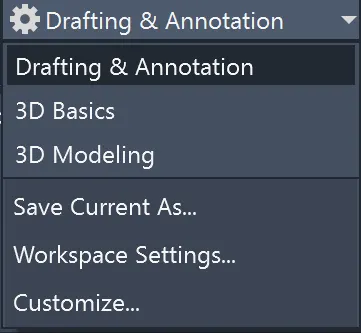
when we choose 3d modelling the following ribbon as shown in the following images occur.
Ther are many such basic things to be followed, By drawing the following drawing how to start a 3D modelling drawing is learnt.
example,any surface can only be projected along Z-axis, to achieve a solid 3-D model the object must be drawn using poly line or the plain figure need to be joined using join command.
INTRODUCTION: Any drawing when converted in to a 3D model, it is easy to undestand its phisical appearence and many other features for example in civil engineering various opening like doors and windows, and when reinforcemnt is drawn in 3D, the cranked bars, the lap length, the bend shapes etc can be easily understood. It is very important to change the UCS when working in 3D. Always the drawing in drwn in the X-Y plane and projected in Z axis. FOr this either you can use extrude command or press pull , when an uniform cross section has to be obtained after exrution.
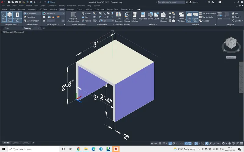
The following drawing is just a table, the following procedure was followed to draw it.
PROCEDURE:
Step 1:
at command prompt, units command was used and the units were set to engineering.
Limmax was used and the highest point of limit was set to 10',10'
Step2:
From the 3D modelling ribbon, from the view ribbon, from the view manager the view wass selected as s-w isometric.
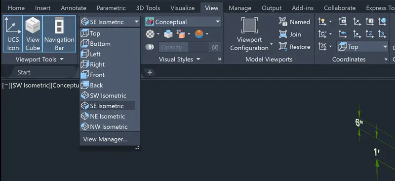
Then the UCS will show all the three coordinate axes.
Step 3:
Again from the same view manager the ucs is selected as left so that the X-Y plane appears to the left and the drawing can be done only in this plane, the following image shows the same, the plane parallel to xy plane on this only plain drawing was drawn and the crass section will be looking as shon in the image.
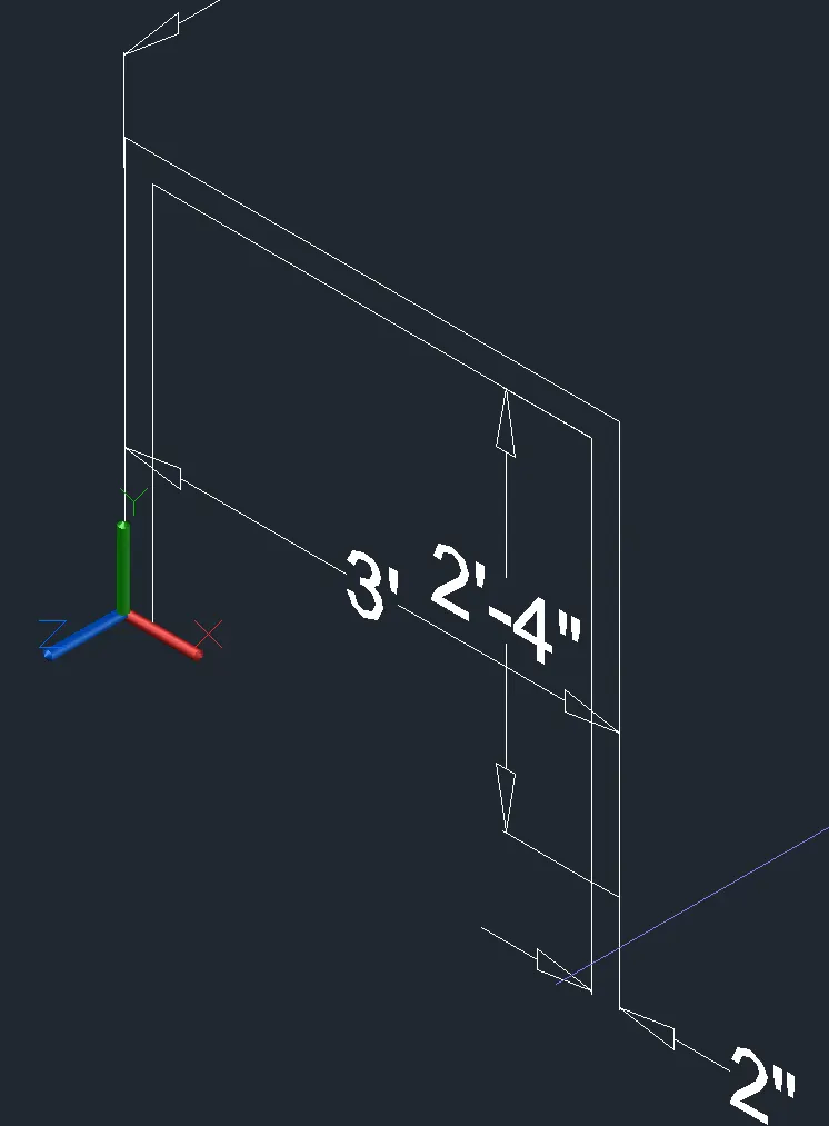
Step 4:
After that extrude command was given and the length of excrusion was given, the excrusion only takes along the z axis.
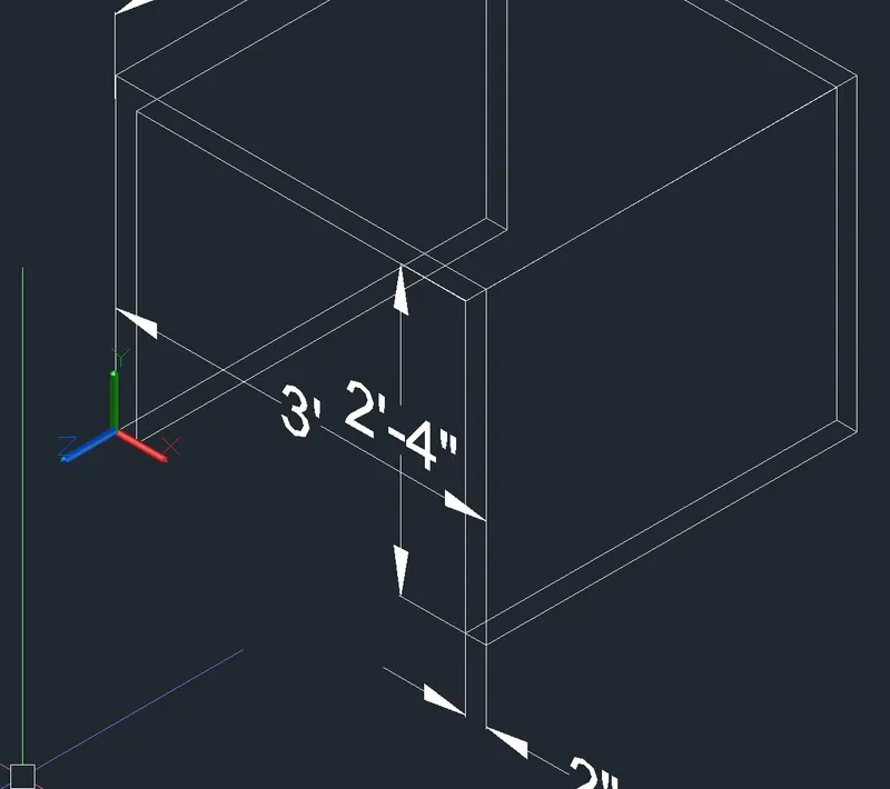
Step 5:
In the view option we can choose the shades of gray then the image looks as follows.
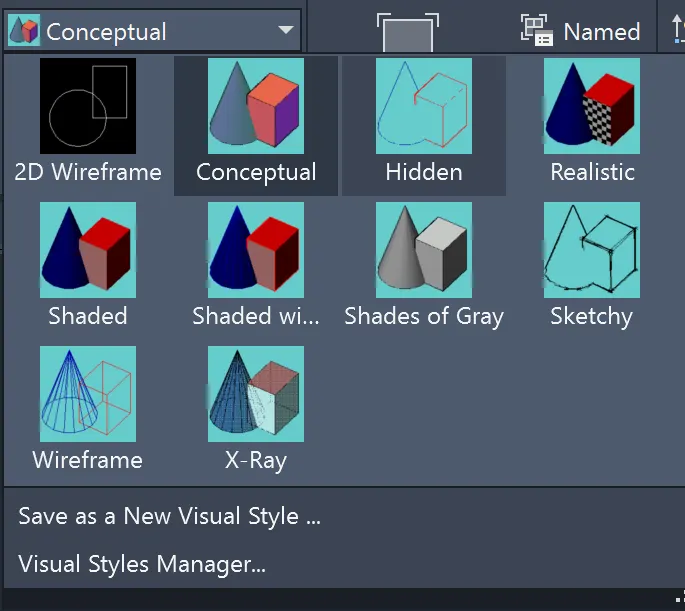
Step 6:
at command prompt D command was used and the arrow size, the units precision and the text sizes were chose to suit the drawing.
Here also the dimensioning can be done in only along X, Y axis and to annototate the Z axis, we have to keep X-Y plane parallet to the direction of annotation.
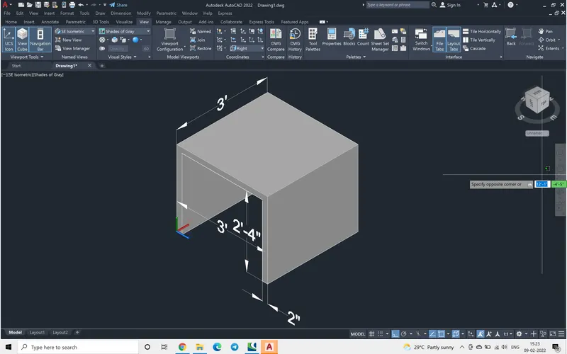
This image is wireframe image
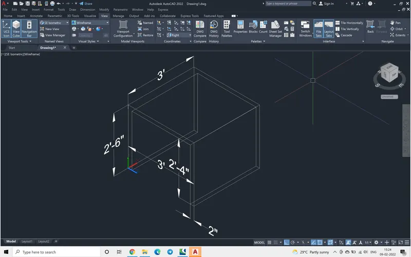
This is a conceptual image.
*****************************************************************************************************
AIM: The aim of this question is to understand various 3D modelling commands in Auto cad, her extrude and loft commands are used basically.
INTRODUCTION: Any complex shape which has different sizes of same shape or different sizes od different shapes can be made in to a solid object by using command loft.
PROCEDURE:
Step 1:
at command prompt S-E isometric view was selected,
then a recatngle of 2x2 dimension was drawn,
Step 2:
Using offset command , 6" as offset another rectngle was drawn.
Step 3:
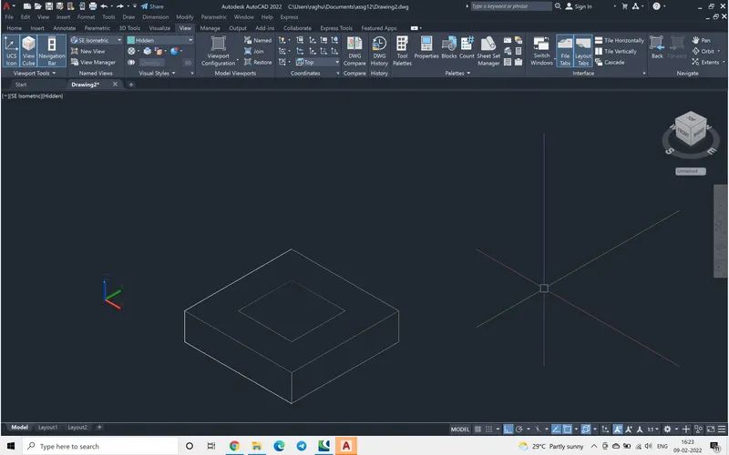
Extrude command was given, then the extrusion height was mentioned, the following figure is obtained after extrsion.
Step 4:
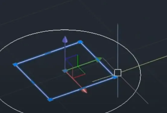
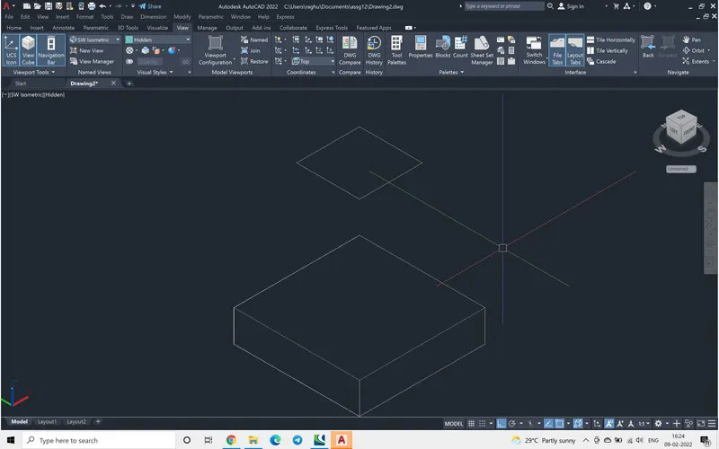
When the smaller square was selected the cursor highlights a shown in the figure they are called gismo, it will allow the this square to move in any direction either Z, Y or X, here we will move in the Z direction and hte following image will show that the small rectangle is moved away.
Step 5:
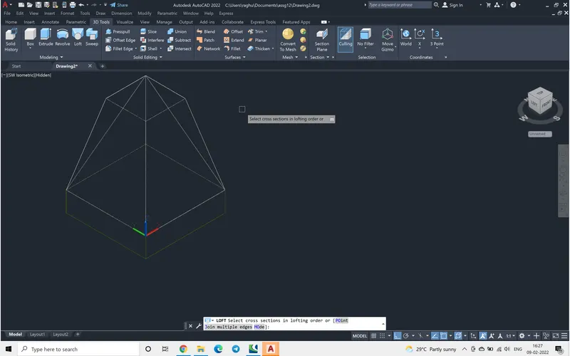
command loft is used, first the bigger square then the smaller square is selected, then the figure would look like this.
Step 6:
at command prompt D command was used and the arrow size, the units precision and the text sizes were chose to suit the drawing.
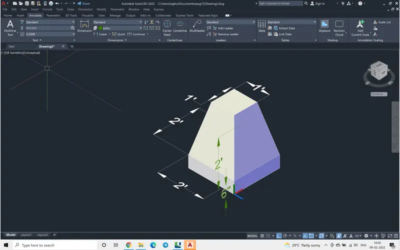
Command Dimlinear was used and can be annotated in the plane parallel to X-Y plane. to give it in the z direction, again UCS needs to be made parallel to that z plane.
**********************************************************************************************************
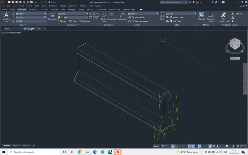
AIM: The aim of this task was to understand the 3D profile of an I section girder.
INTODUCTION: Here initially the cross section was drawn, keeping again the X-Y plane parallel to the cross section of the I girder. the UCS shown in the image shows the sme.
PROCEDURE.
Step 1:
at command prompt S-E isometric view was selected, then the left view was selected so that X-Y plane is made parallel to crass section of the I girde.
Step -2
Using l and offset command keeping the dimensions given as offset, the following cross section is achieved.
Step 3:
Using the extrude command and giving the extrusion lengtnas 10' the following image can be obtained.
Step 4:
at command prompt D command was used and the arrow size, the units precision and the text sizes were chose to suit the drawing.
Command Dimlinear was used and can be annotated in the plane parallel to X-Y plane. to give it in the z direction, again UCS needs to be made parallel to that z plane.
The following image is a conceptutal image.
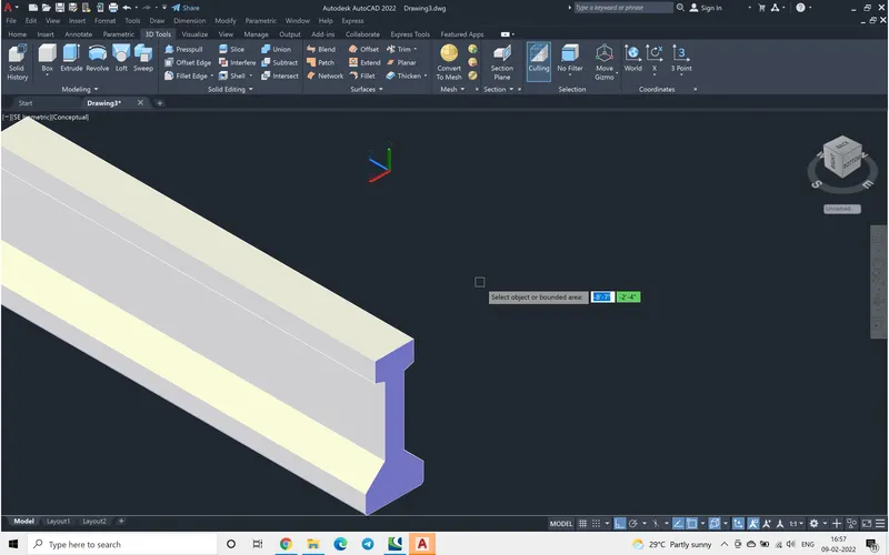
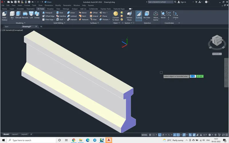
The folowing is Hidden image
******************************************************************************************************************88
AIM: The following task has little extra degree of toughness, the aim was to draw the column with drop panel and column head , has to be shown in 3D model.
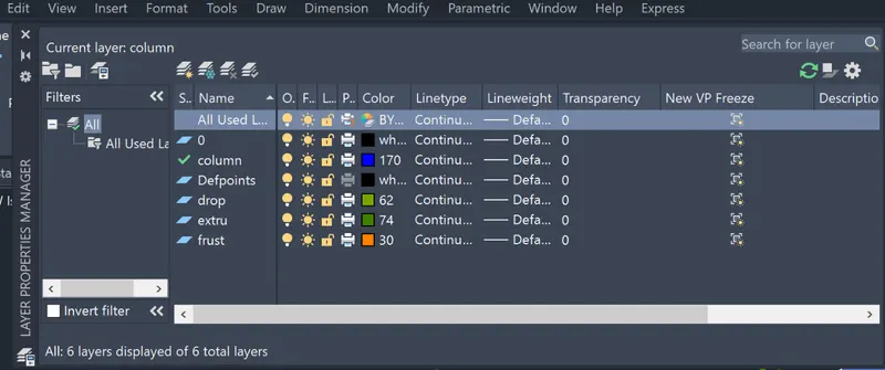
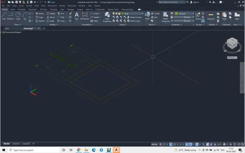
INTRODUCTION: In this the drawing was done from the top to bottom. The three different layers were created for each feature, column, frustum and drop. when the drop panel was drawn the other layers were kept off, when column head ws to be drawn thr drop panel was put off and frozen and then column were drawn keeping the other layers off and frozen and then union command was used to join them.
PROCEDURE:
Step 1:
Units commad
Engineering command with 0'-0" precision
Step 2:
Limmax, 15', 15' was chose
Step 3:
Layers command
three new layer column, frustum and drop were created.
Step 4:
S-E isometric view was chose.
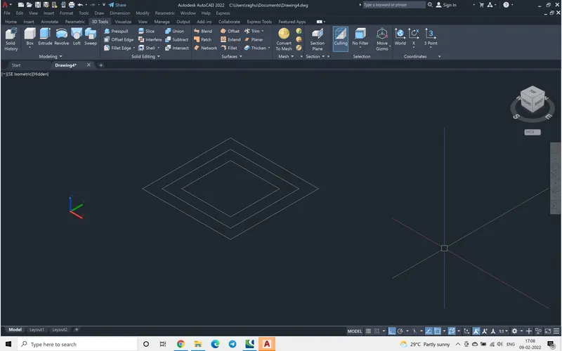
Step 5:
then three squares were drawn , and dimensional annotation was done as shown below
Step 6:
The top drop panel was extruded and layer was put off so it is not seen in the following image
Step 7:
The frustum can be obtained by using the command loft by keeping current layer as frustum, gismo was used to move the small square down by 1'.
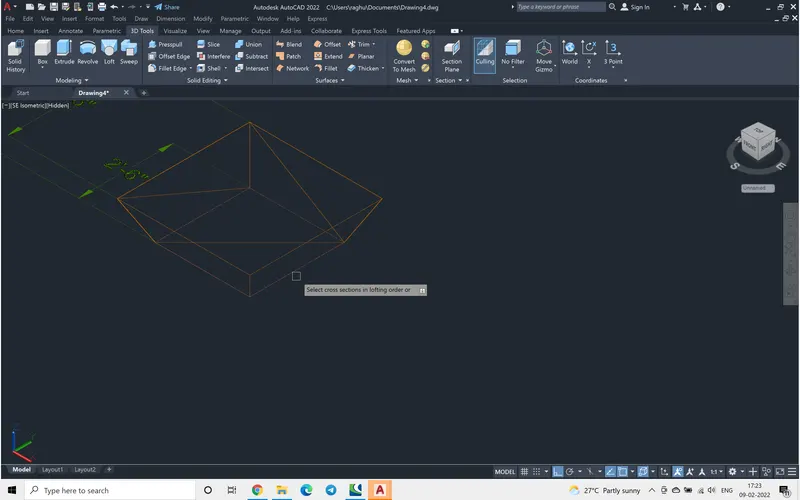
Step 8:THe conceptual image will look like this.
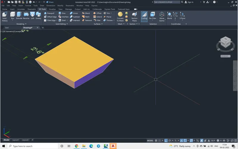
Step 9:
Then the frustum layer was put off.
Step 10:
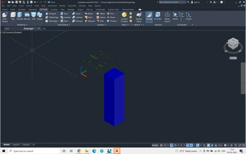
Noe the command extrude was applied to layer column and to smaller square to an extrusion length of 10'
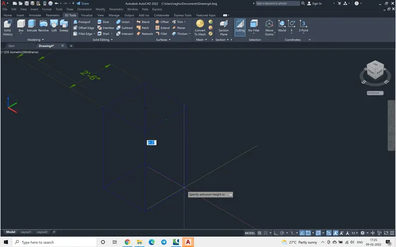
The following is the shade image
Step 10:
Now one by one the frustum layer is on here
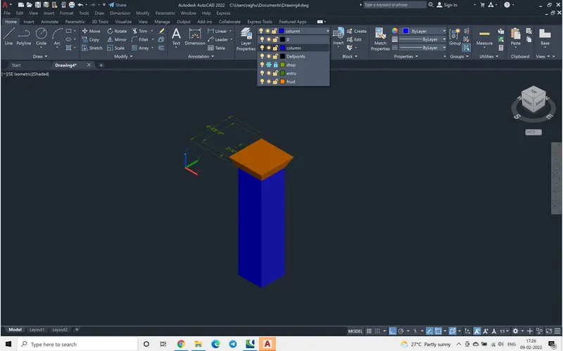
The drop layer if on here.
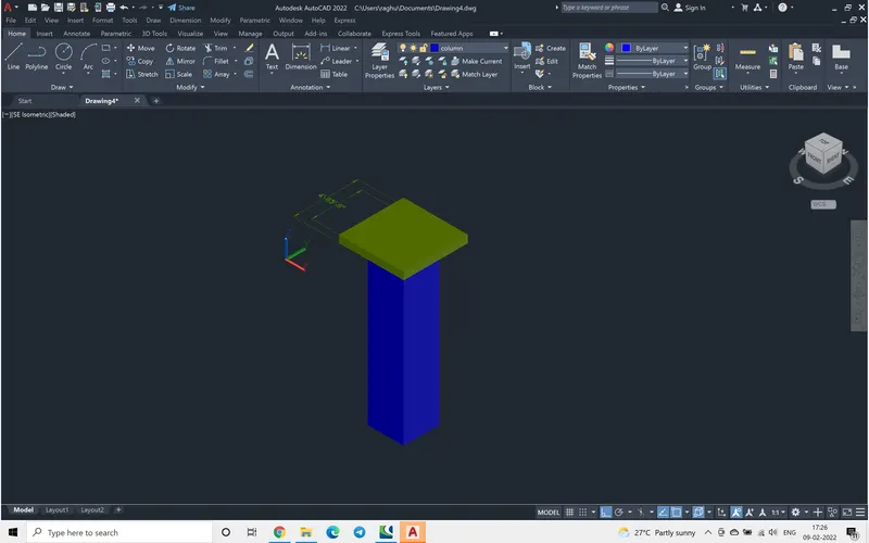
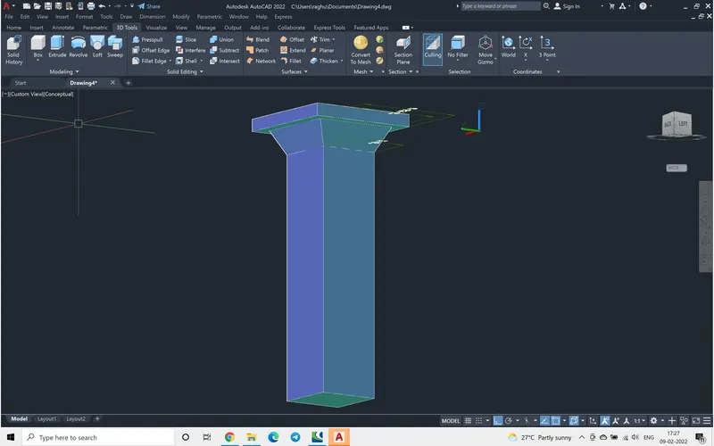
The image would look like this when all the three layers were on.
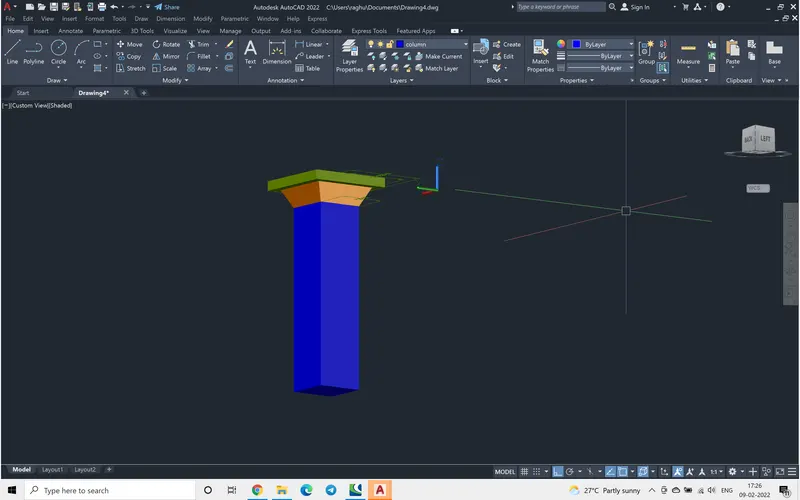
Step 11:
Keeping column layer as current layer, using Union command the column would finally look like this.
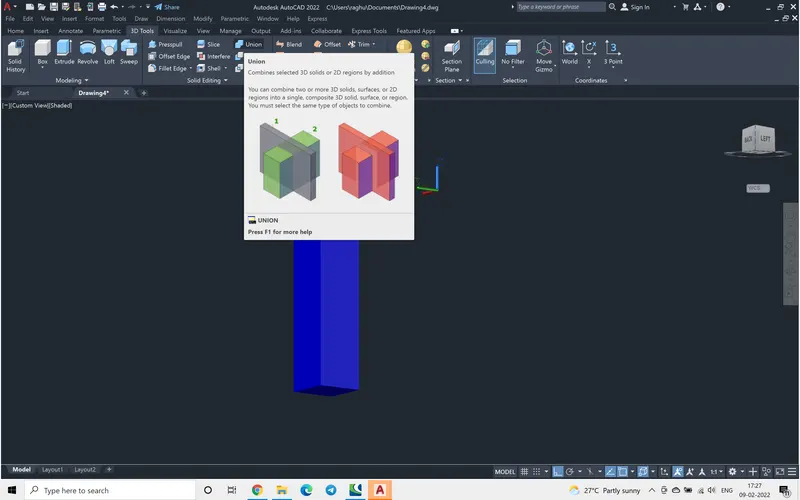
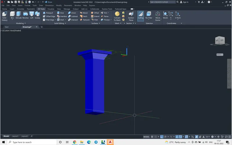
Step 12:
at command prompt D command was used and the arrow size, the units precision and the text sizes were chose to suit the drawing.
Command Dimlinear was used and can be annotated in the plane parallel to X-Y plane. to give it in the z direction, again UCS needs to be made parallel to that z plane.
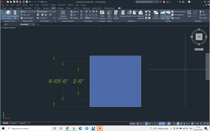
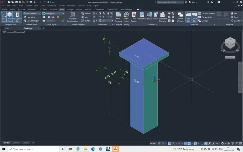
USing Dimlinear the column is annotated.
The top view of the dimension.
The isometric view witht he dimensions.
*************************************************************************************************
AIM: The aim of the task is to draw the gabled end of an instructial building.
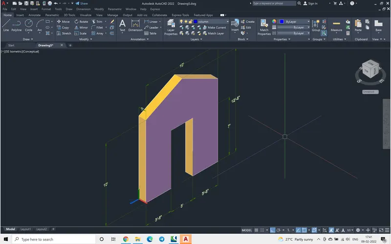
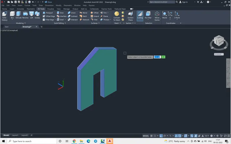
INTRODUCTION: Here the UCS was set parallel to the elevation of the gabled wall. the following image show that, in 3D it is very important to definr the plane on wich we are drawing our plane figure and what is the direction of projection and set the Z axis to that direction. Here the thickness of the gabled end is parallel to Z axis.
PROCEDURE
The following procedure followed
Step 1:
Units commad
Engineering command with 0'-0" precision
Step 2:
at command prompt S-E isometric view was selected, then the left view was selected so that X-Y plane is made parallel to crass section of the I girde.
Step 3:
using line command a line of 12'-6" was drawn
then offset command was used with offset distance 1.5" so that the opening is done
then again offset command this time offset dist with 3.5' then the end of the gabled wall is schieved, draw the horizontal lines a bottom
now again offst command 7' as offset dist, the opening is completed.
the gabled edges height was given 10' then the inclined lines were drawn, meeting 12'-5" and 10' on either side.
Step 4:
Join command was used
Step 5:
extrude extrusion length 1' was given
Step 6:
at command prompt D command was used and the arrow size, the units precision and the text sizes were chose to suit the drawing.
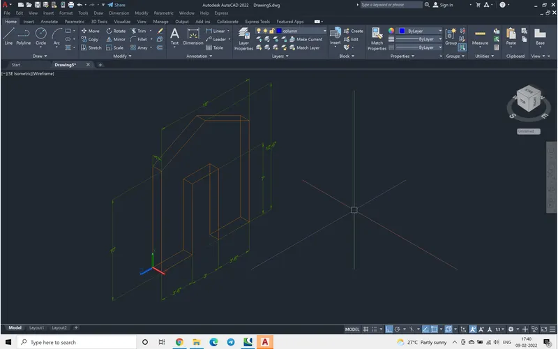
Command Dimlinear was used and can be annotated in the plane parallel to X-Y plane. to give it in the z direction, again UCS needs to be made parallel to that z plane.
USing Dimlinear the column is annotated.
The following is aconcetual image
The following is wireframe image
The following is a conceptual image with dimensions