Week 3 Challenge
Aim: The Aim of this challenge is to understand the IRS codes and apply the different IRS specified car loads ( live loads) on the super structure and analize the super structure using Stadd Select.
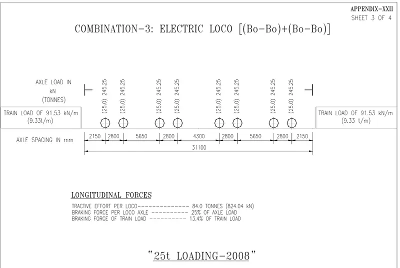
Introduction: IRS means Indian Railway standards, when compared to IRC loads the railway loads ( live loads) are heavy but distributed over a very longer lengths. The following picture shows the various moving loads defined.
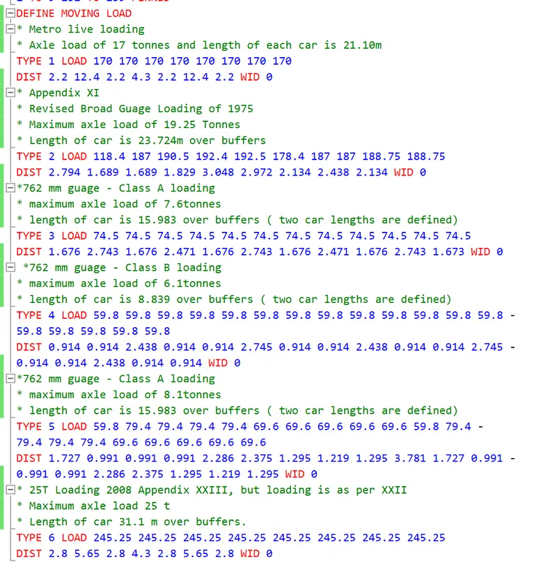
here type 1- 2 cars are defined this metro cars are not defined in the IRS bridge rules, but this cars are specified by Indian Railway standards specially for Metro design.
Type -2 - single car (23.724 - 1.6= 22.124m)
Type 3- 2 car lengths are defined
Type 4- 2 car lengths
Type - 5 2 car lengths
Type- 6 2 car lengths
Type -2
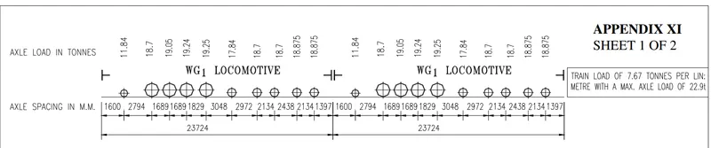
Type-4

Type -3

Type-5

Type-6
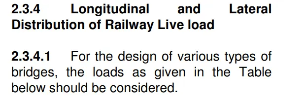
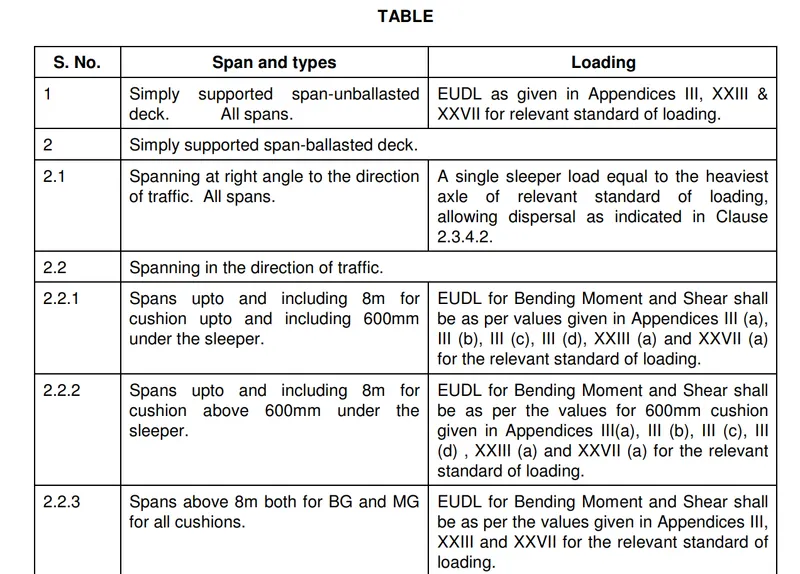
According to Bridge rules provisions page 6 gives the loads to be considered according to the span and types. Since ours is unballasted deck No.1 condition is considered.
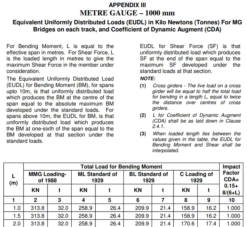
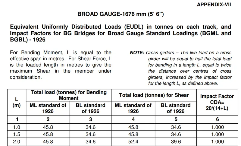
In IRS the term EUDL is often mentioned, it is Equivalent uniformly distributed loads and its expanation is that what ever the length of axle loads which the span can accommodate are converted to uniformly distributed loads and are tabulated.
Appendix III shows for meter guage
Appendix VII shows for Broad Guage.
ML stands for Main Line, simply supported spans
BL stands for Branch line, simply supported spans
C stands for continuous super structure


Description on super structure.
The span of the super structure is 25m, the deck width is 26m.
Two carriage way widths with a barrier inbetween is given.
The deck has a footpath on side of deck.
The deck is not divided equally for the carriageways.
The super structure is a I girder bridge. Total eight number of I girders are placed.
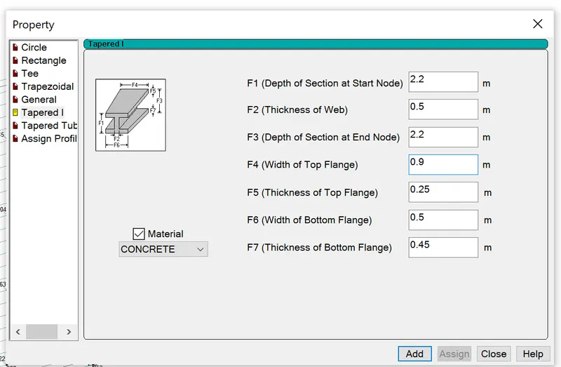
The depth of I gider assumed is 2.2 m, they are spaced at 3.5m center to center and an over hang of 0.75m on either side. The top flange width is assumed as 0.9m and bottom as 0.5m.
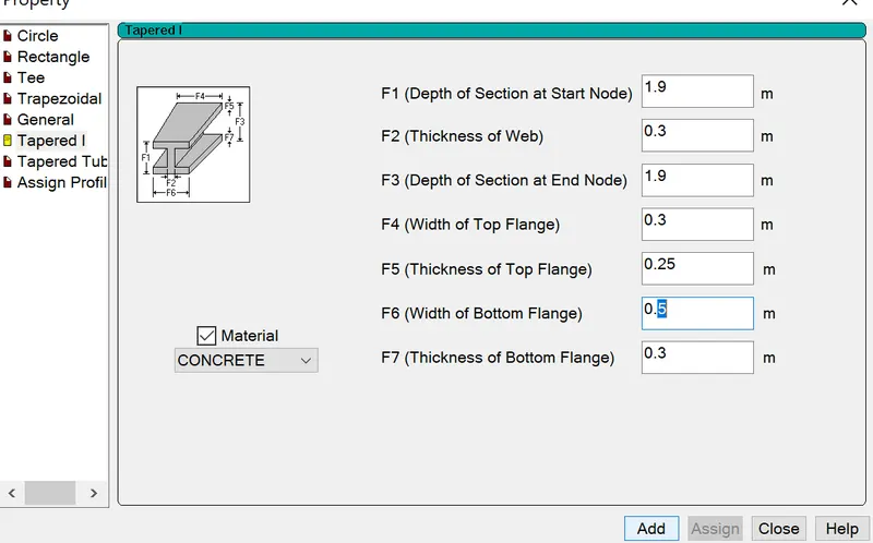
The depth of cross girder assumed is 1.9 m
The Deck width is 26m
The span of the deck is 25 m.
The deck is divided in to two carriage way lines, having a barrier in the middle. The deck is having a foot path on the left end. The deck is not divided into equal halves as one end is occupied with footpath.
The thickness of the slab is considered as 0.3m
*******************************************************************************************************
****************************************************************************************************
****************************************************************************************************
Procedure:
The analysis of the IRS live loads on the super structure is carried out using Stadd.
The entire structure is modelled as grillage model.
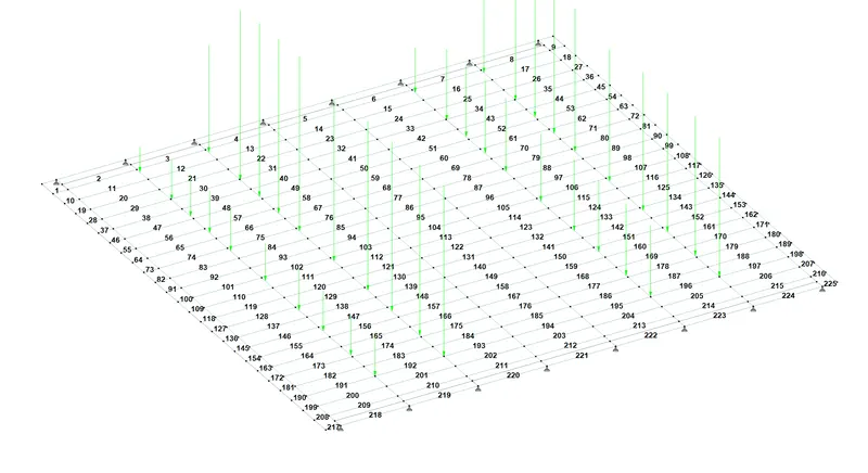
The following picture shows the nodes defined. The supports are also seen.
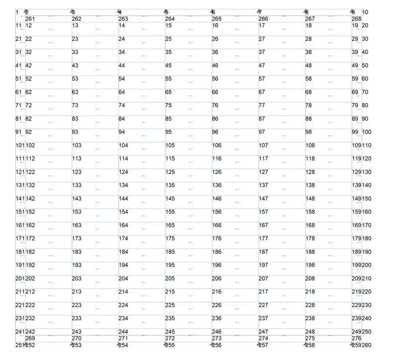
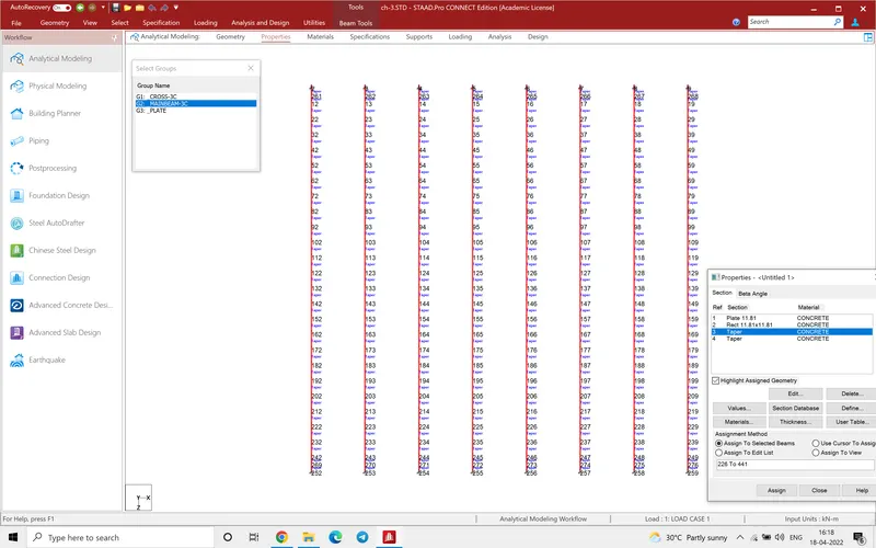
The following Image shows the main girders of the model.
The same image shows the groups here created are plate group and cross girder group.
After defining the members the specifications like member properties the material type and the supports are defined.
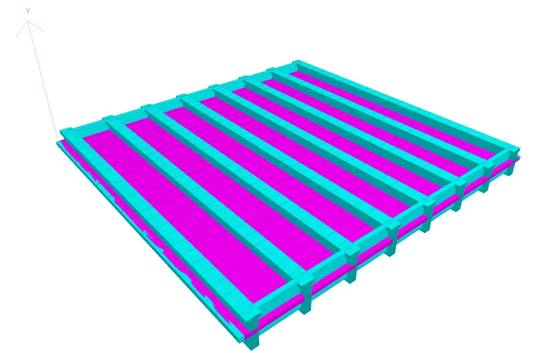
The following Image shows the 3D image
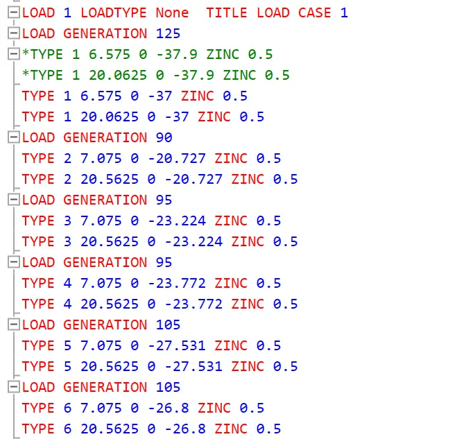
The following load generations are defined
The following figure shows the type 1 to type-5 car loads, which is earlier explained in the introduction it is metro car and other types of cars, the car is place at X coordinate 6.575 m, Y coordinate 0, Z coordinate -37m ( Z axis defines the length of the span and the vehicle length) which is the vehicle staarts at one end and with 0.5m increment it moves for every genaration.
The number of load generations are calculated as-the length of the total car length defined here two cars are defined plus the span length of the bridge. here it is 25m.
It is 65 meter approximated and since each generation it moves 0.5 m therefore 65/0.5 =130 but here it is given as 125 number of generations.
Similarly for other load type or other train cars also the procedure is followed the same.
125+95+95+105+105 generations are generated.
Here there are two spans, so the same vehicle type on either of the spans placed and generated parallelly in the same direction. The following figure shows the two train of same loads on either of the carriage ways.
*************************************************************************************************************
*************************************************************************************************************
*****************************************************************************************************************
Results
The following results are obtained
THe maximum bending moment for main girders.
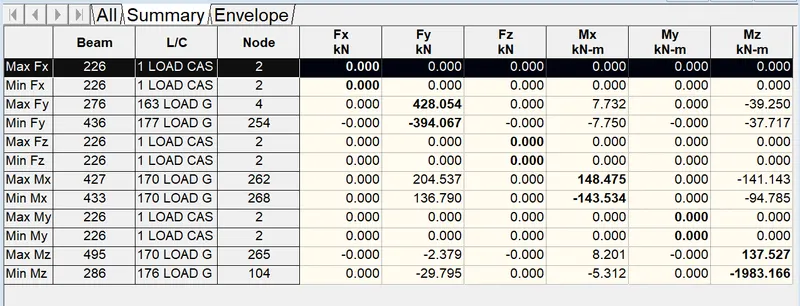
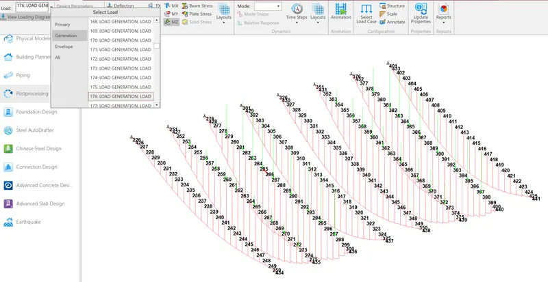
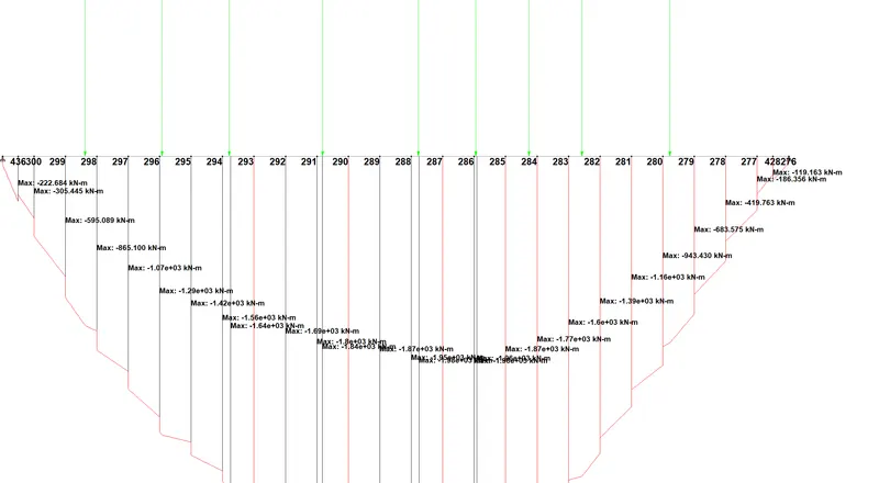
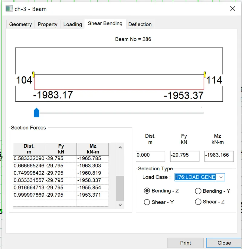
The 286 bem number is getting maximum bending moment. The load case is 176, the following diagram shows the results.
****************************************************************************************************************
*****************************************************************************************************************
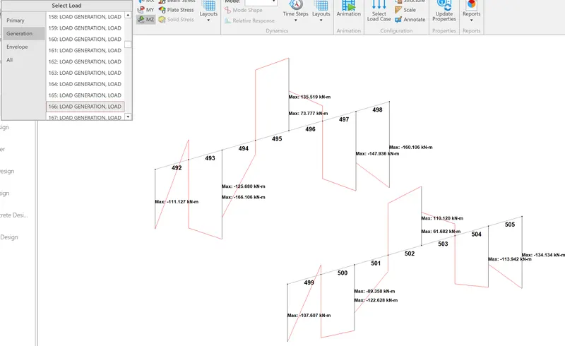
Cross girder bending moments
The maximum bendinf moment for cross girder is given in the following diagram
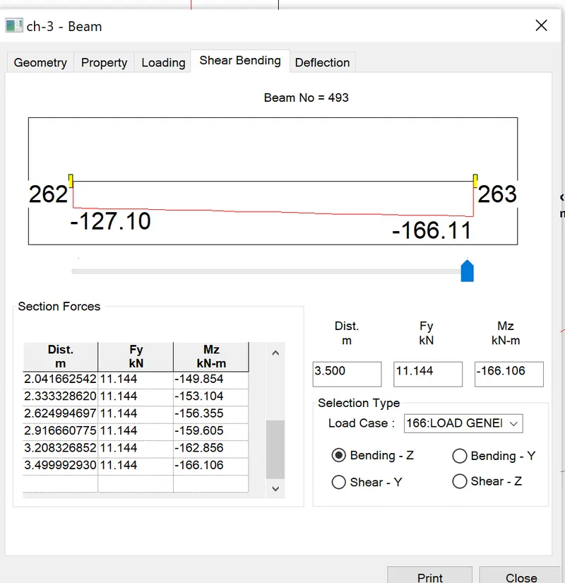
The 493 beam had maximum bending moment of 166.06kN-m
and the corresponding shear force can also be seen.
***************************************************************************************************
****************************************************************************************************
The plate stresses.
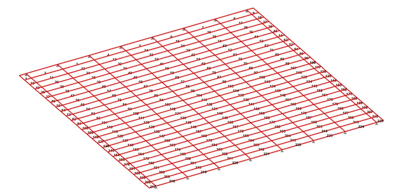
The slab above the main girders is modelled as above, as plate element. The numbering of the plates are given in the figure.
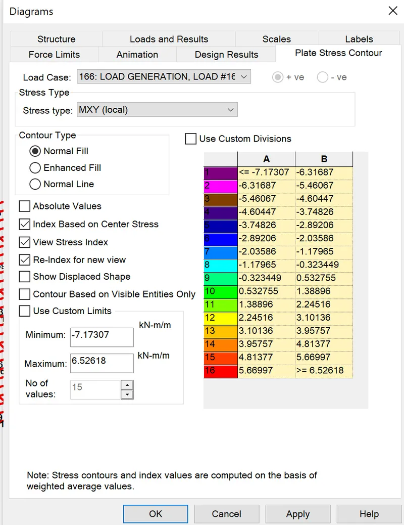
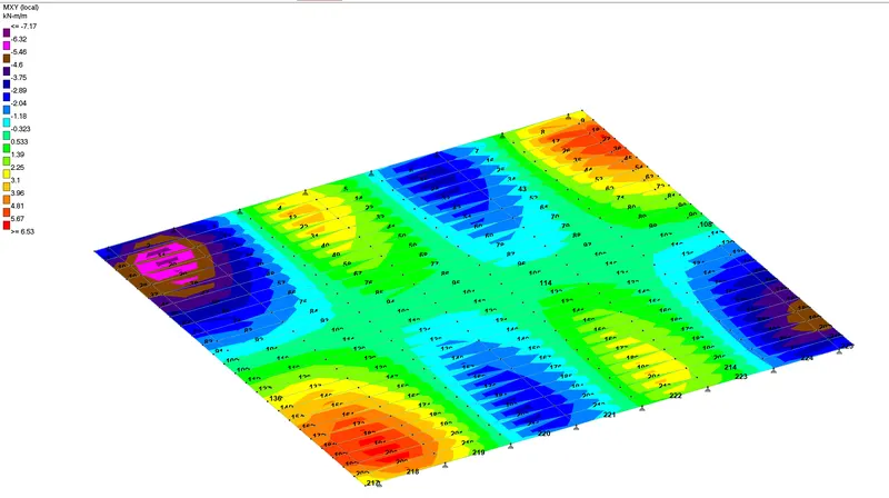
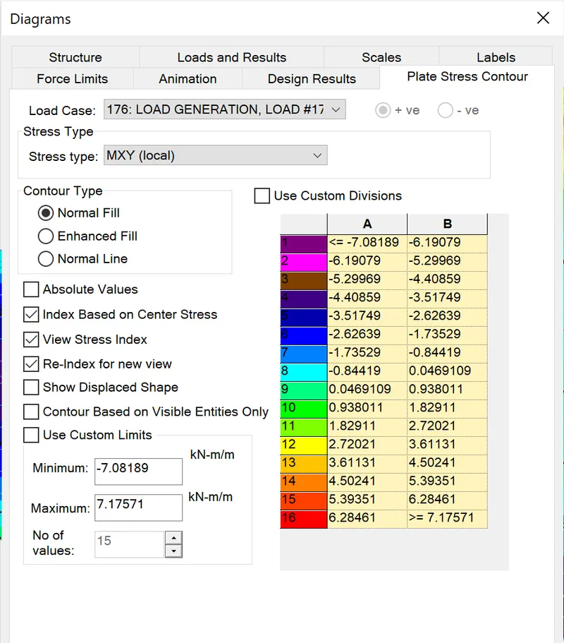
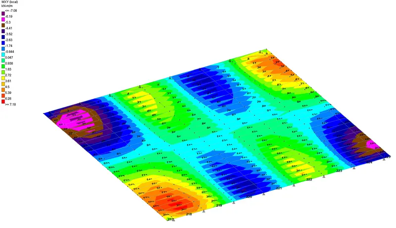
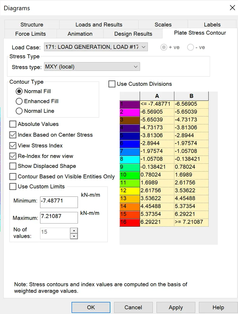
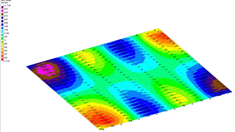
Here for the slb the mximum stresses Mxy local, occur in load case 171, the sam eis shown in the above figure. Similarly for SQx, SQy ca also be obtained.
****************************************************************************************************
*************************************************************************************************
Reactions on the supports.
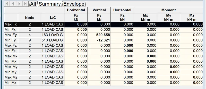
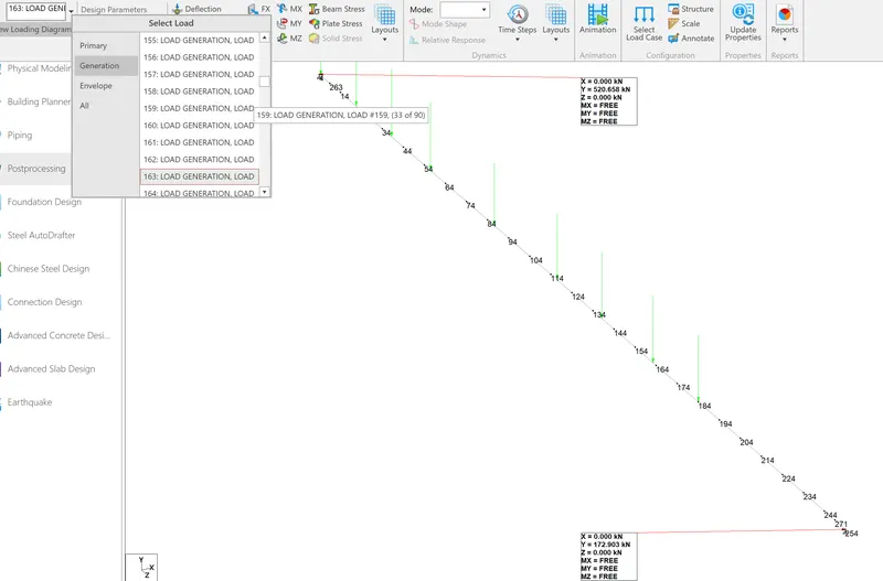
For the load case 163 and the support 4 is recieving maximum reaction.