Creating a Wardrobe detailed drawing, Floor Plan, Kitchen Layout and Column Detail using AutoCad
AIM: TO DRAW THE PLAN, ELEVATION AND SECTION OF WARDROBE.
INTRODUCTION: It is very imporatant to give the correct details on the furniture for reducing the wastage and proper planning for the materials.
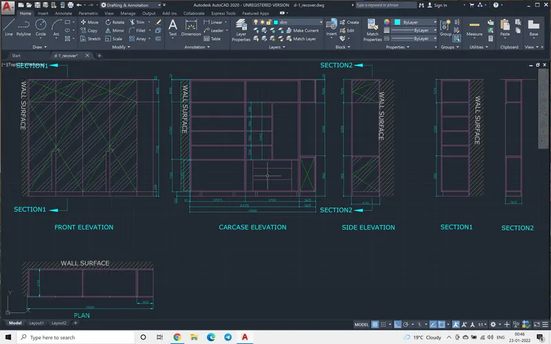
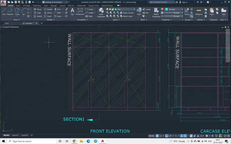
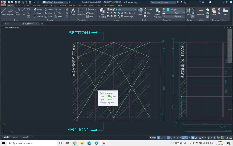
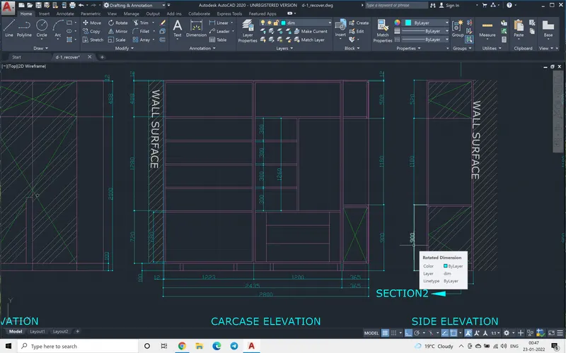
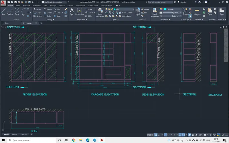
The following drawing shows the various sections of the wardrobe, its elevation and partitions inside the wardrobe. The thickness of board is given 20mm and 12mm thin sheet at the back which flushes will wall surface. The following commands were used to draw, Units, Limits, layers, polyline, offset, fillet, trim, dimensionstyle,Mtext, hatch,copy and other like divide scale mirror etc were used.
PROCEDURE:
Step 1:
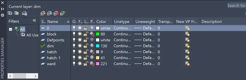
Various required layers were formed initially,
at command prompt layers, the following shown layers were used.
Step 2:
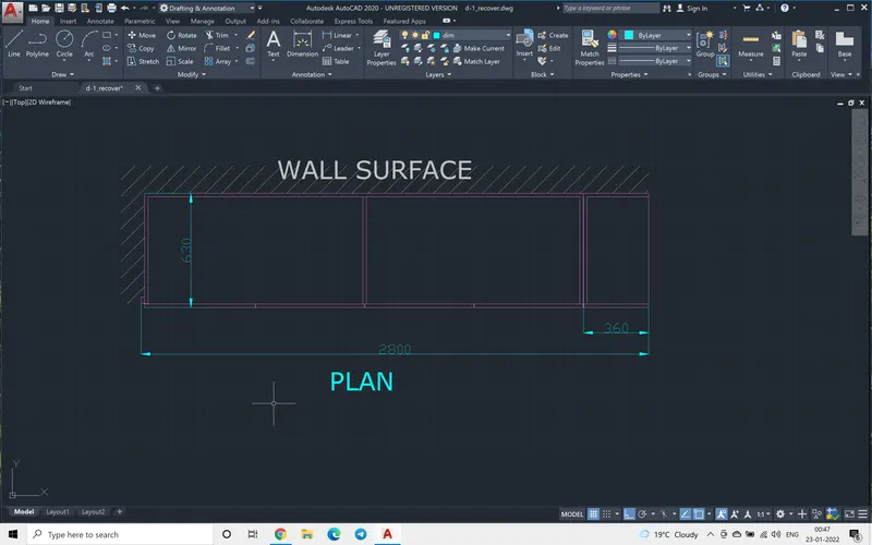
At the command prompt, by using the command polyline, offset, divide, the given figure was drawn.
Step 3:
once the plan and front elevation were done the carcase , side elevations were drawn
Step 4:
Next the section1, section2 were drawn.
Step 5:
After entire drawing was done, the dimensioning was done keeping dim layer active.
****************************************************************
***************************************************************
**********************************************************************
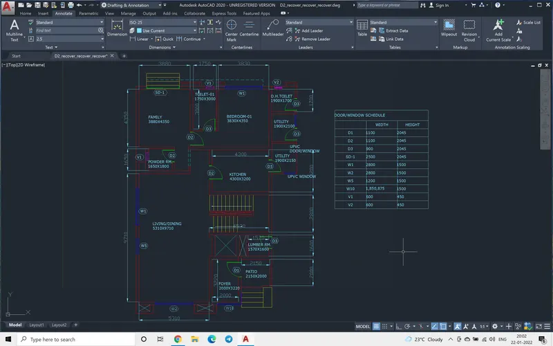
AIM: TO DRAW THE PLAN of a house.
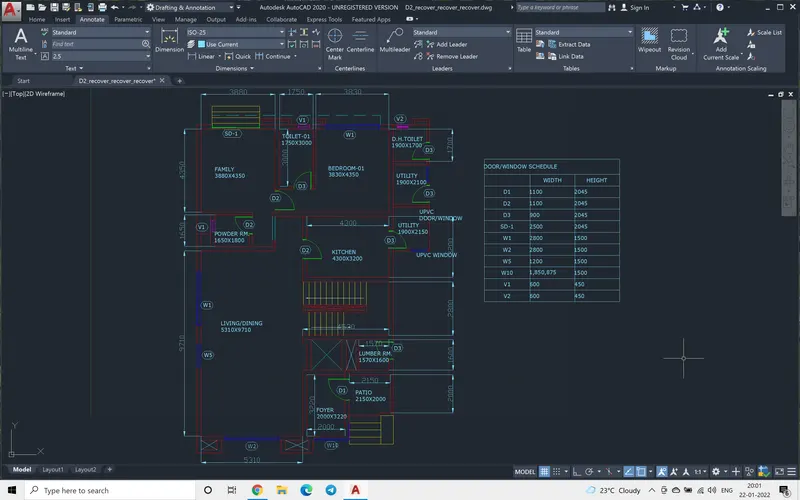
INTRODUCTION: The following house plan is drawn with according to the dimensions mentioned in the plan. The layers play a very important role in highlighting the features of the plan. The following commands were used to draw,Units, Limits, xline,layers, polyline, offset, fillet, trim, dimensionstyle,Mtext, hatch,copy and other like divide scale mirror etc were used.
PROCEDURE:
Step 1:
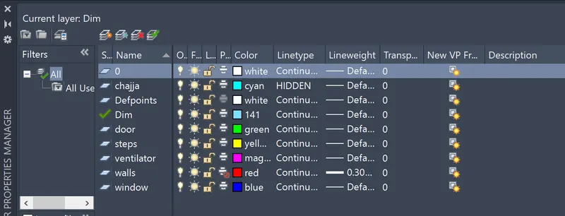
The following table shows the number of layers used in the drawing.
each layer was given separate color .the line thickness was kept the same zero for all and onlt one hidden line was used.
Step 2:The drawing was started by xline command and it was drawn by giving a start at the top and slowly moved to the bottom. few of the dimensions were assumed like at the main entrance the step length was not given and the plant box dimensions were not mentioned.
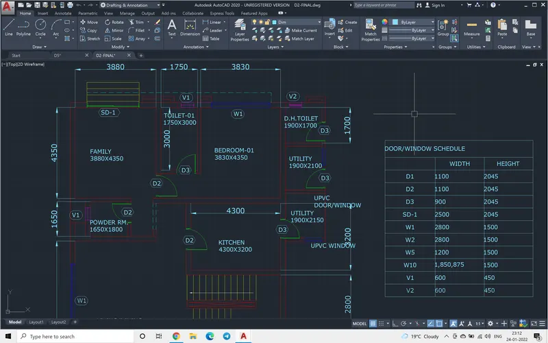
Step 3: Once all the walls were done the doors were assumed and placed at the position. The door schedule is shown on the drawing.
Step 4: Once the doors are located then the windows and ventilators were done, the window and ventilator schedule is also mentioned.
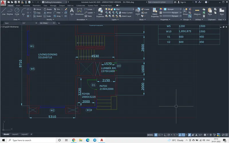
Step 5: then the dimsty was set and keeping the layer dim active all the dimensioning was done.
THe following drawing is achieved as shown.
^^^^^^&&&&&&^^^^^^^^^^^^**&&&&&&&&&&&&^^^^^^^^^&&&&&&&&&&&^^^^^^^^^^^^^^^^
$$$$$%%$$$$$$$%%%%%$$$$$$%%%%%%$$$$$$$%%%%$$$%%%$$$$$$%%%%%%$$%%%$%$
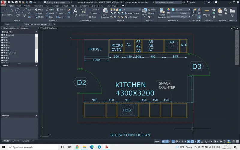
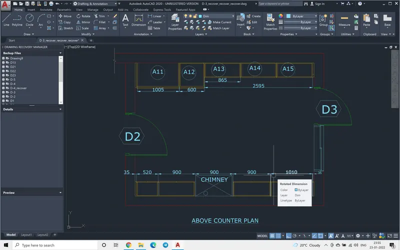
AIM: TO DRAW THE kitchen details.
INTRODUCTION: The following kitchen plan is drawn with according to the dimensions mentioned in the plan. It is very important to properly designing the location of various accessories in the kitchen mainly like hob, over head cuboards, below storage cubboards, location of fridge and oven etc. This represents the design of modular kitchen. The layers play a very important role in highlighting the features of the plan. The following commands were used to draw, Units, Limits, xline,layers, polyline, offset, fillet, trim, dimensionstyle,Mtext, hatch,copy and other like divide scale mirror etc were used. This is also a part plan of the above house plan and wardobe details are present in this drawing.
PROCEDURE:
Step 1:
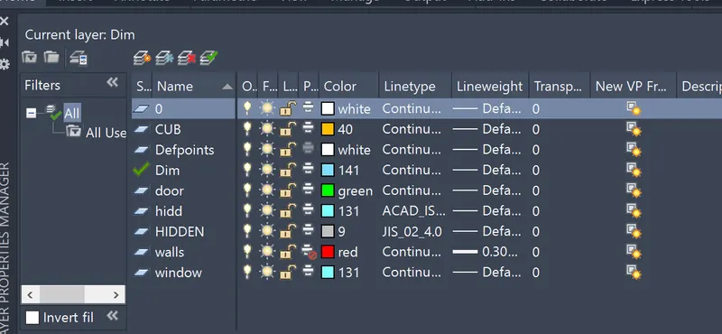
The following table shows the number of layers used in the drawing.
each layer was given separate color .the line thickness was kept the same zero for all and only one hidden line was used.
Step 2:The drawing was copied from the above question house plan.
Step 3:Intially the below counter plan was drawn using layers, polyline, offset, fillet, trim, dimensionstyle,Mtext, hatch,copy and other like divide scale mirror etc were used. Then later the above counter plan was done.
Step 4: Once the doors are located then the window was drawn.
Step 5: then the dimsty was set and keeping the layer dim active all the dimensioning was done.
THe following drawing is achieved as shown.
@@@@@@@@@@@@@@@@@@@@@@@@@@@@@@@@@@@@@@@@@@@@@@@@@@@@@@@@@@@@@@@@@@@@@@@@@@@
@@@@@@@@@@@@@@@@@@@@@@@@@@@@@@@@@@@@@@@@@@@@@@@@@@@@@@@@@@@@@@@@@@@@@@@@@@@@
@@@@@@@@@@@@@@@@@@@@@@@@@@@@@@@@@@@@@@@@@@@@@@@@@@@@@@@@@@@@@@@@@@@@@@@@@@@@@@@@@@@@@@@@@@@@@@@@@@@@@@@@@@@@@@@@@@@@@@@@@@@@@@@@@@@@@@@@@@@@@@@@@@@@@@@
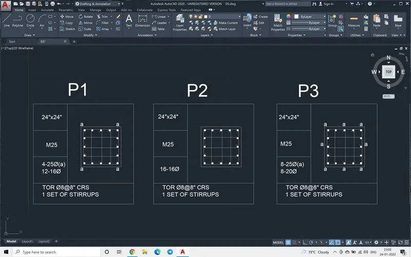
AIM: TO DRAW THE Column reinforcement details.
INTRODUCTION: The following drawing shows the reinforcement deatails of different columns.
PROCEDURE:
Step 1:
Units, Limits were used to set the limits and units for the drawing
Step 2:
The column section was drawn using polyline, then offset, circle , hatch, mirror then line commands were used in order to finish as shown in the figure.
The column dimension was 2'x2' and offset of 1.5" was given with a circle of 8mm dia was drawn.
Step 3: A table was drawn for each separate column and the details were filled next to each column.
Step 4: Mtext command was used to write the details on the reinforcement, %%C for dia symbol was used.
The following drawing is achieved.
@@@@@@@@@@@@@@@@@@@@@@@@@@@@@@@@@@@@@@@@@@@@@@@@@@@@@@@@@@@@@@@@@@@@@@@@@@@@@@@@@@@@@@@@@@@@@@@@@@@@@@@@@@@@@@@@@@@@@@@@@@@@@@@@@@@@@@@@@@@@@@@@@@@@@@@@@@@@@@@@@@@@@@@@@@@@@@@@@@@@@@@@@@@@@@@@@@@@@@@@@@@@@@@@@@@@@@@@@@@@@@@@@@@@@@@
AIM: TO DRAW THE RAFT PLAN
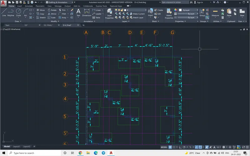
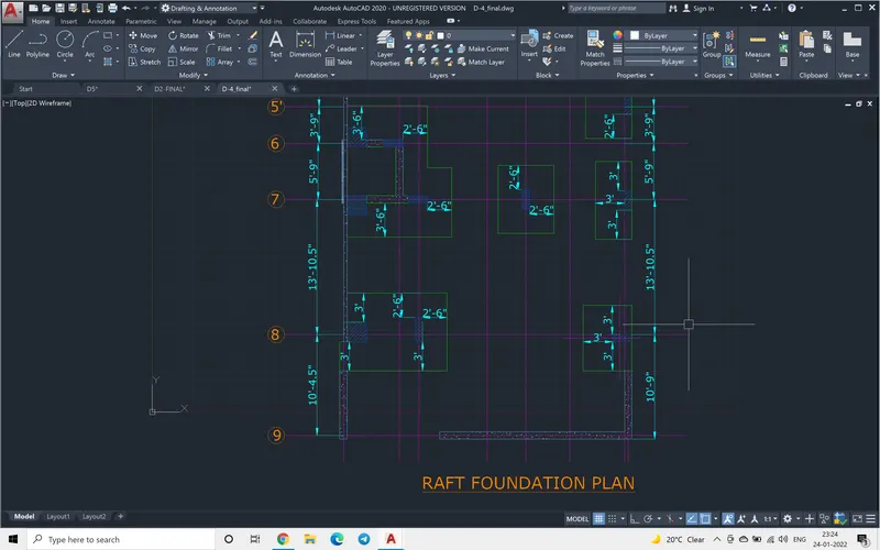
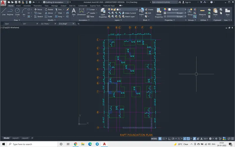
INTRODUCTION: The following raftplan is drawn with according to the dimensions mentioned in the plan. It is very important to properly locate the center lines of the various rafts and location of column for the execution at the site. The layers play a very important role in highlighting the features of the plan. The following commands were used to draw, Units, Limits, xline,layers, polyline, offset, fillet, trim, dimensionstyle,Mtext, hatch,copy etc were used.
PROCEDURE:
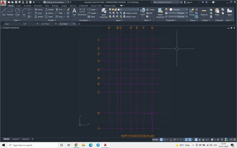
Step 1: at command prompt the layer was typed and the following layers were set
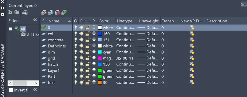
Step 1: Using xline command, the entire grid lines were drawn along with the offset command.
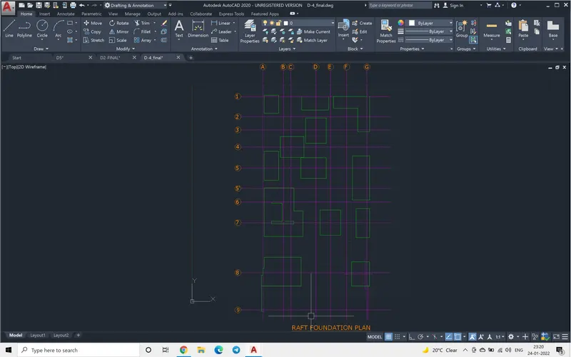
Step 1: The column location and the raft around them was drawn by highlighting the matching layer.
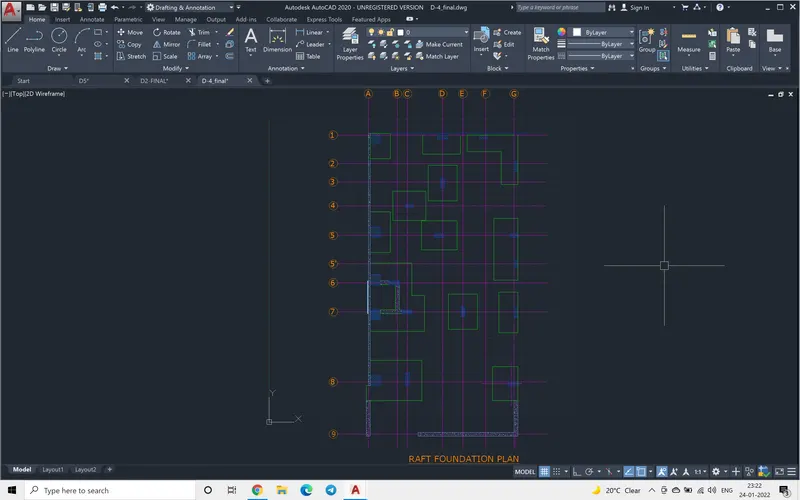
Step 3. There is a 9" thick concrete wall and also 4.5" concret was given , which was drawn and hatched.
It is very important to understand about the hatch scale, here the scale used was 0.05 to 0.005 according the side of the loacation of the hatch, for column the hatch pattern was different and the hatch scale was 1. The column sizes were mentioned in the question itself.
Step 4: the dimstyle was set and layer dim was active, entire grid lines and the sizes of the columna and the rafts were annotated.
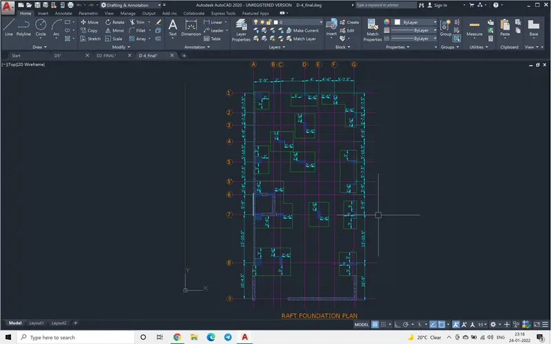
The following drawing was achieved.