Creation of Multiple viewports, Scaling the drawing and setting in Template in AutoCad
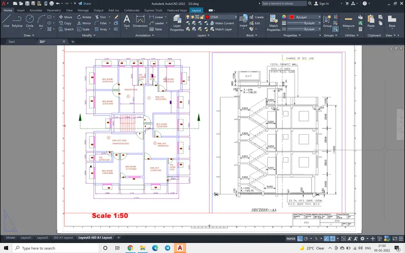
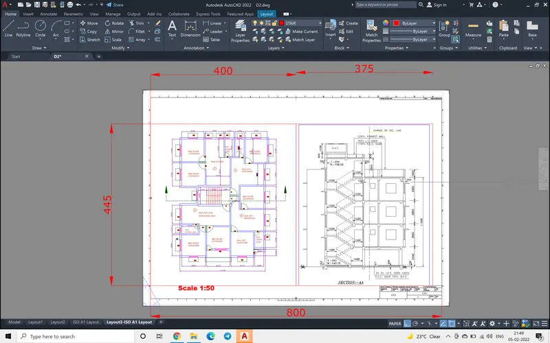
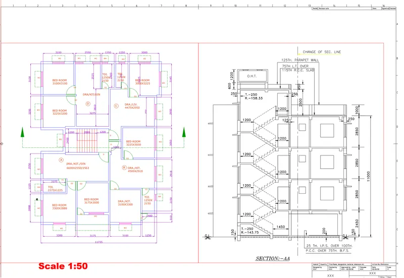
AIM: The aim of this project is to display the sectional elevation and plan from challenge 7 in the layout using template -Tutorial-marc.dwt. And the page size is A1.
INTRODUCTION: From the challenge the drawing for chosen and both the plan and the sectional elevatio-A are shown in the layout.
Two different view ports were choosen vertially in the layout. in the 800 xaxis direction, 400x445 one view port and 375x445 another view port were used. the scale chosen was 1:50
PROCEDURE:
Step:1
In the challenge the page setup of the layout was done to the A1 paper size( 841x597).
For this on the layout in status bar, right click, rename it as D2-Layout3-ISO A1 Layout.
Rightclick on the model in the status bar, then choose from templates, a dropdown list of templates appears, we can now chose tutorial-marc.dwt.
paste the drawing on the layout.
Step :2
Command viewports was used
Choose the single view port and selected a rectangular space on the D2-Layout3-ISO A1 Layout.
Double clicking the viewport we can get in to the model space or use MS command to get in to the model.
Then choose command Zoom and Window, select the drawing , to be shown in the view port.
Now get out of the model space using ps command.
Step 3:
selecting the view port, checking on the drawing aids, scale of the selected view port and chosing 1:50 or what ever the scale we would like to print.
Step : 4
command prompt field command
selecting the object from the list, then the view port, in the viewport the scale of the viewport is choosen. In this only the height of the text to be appeared can also be modified.
initiall it appears like only number 1:50 what ever we have chose. double clicking on the 1:50 we can add text, "scale" to 1:100.
Step :5
In the properties command, or from tab click layout and in layout ribbon tools, clicking lock the viewport, so that there wont be any distrotions in the viewports by accidental selections.
Step 6:
after setting out the viewport, a plot is taken.
an attachment is provided along the procedure in the attachments, please check them.
********************************************************************************
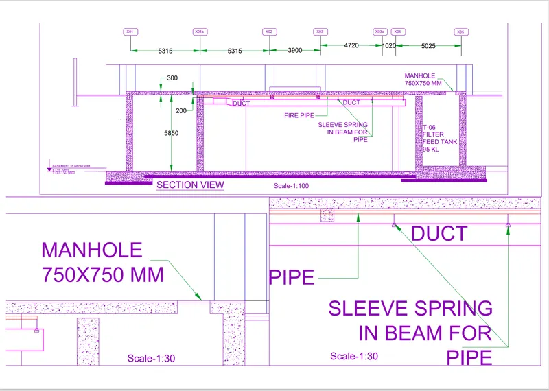
AIM: The aim of this project is to display the sectional elevation industrial basement in the auto cad layout.
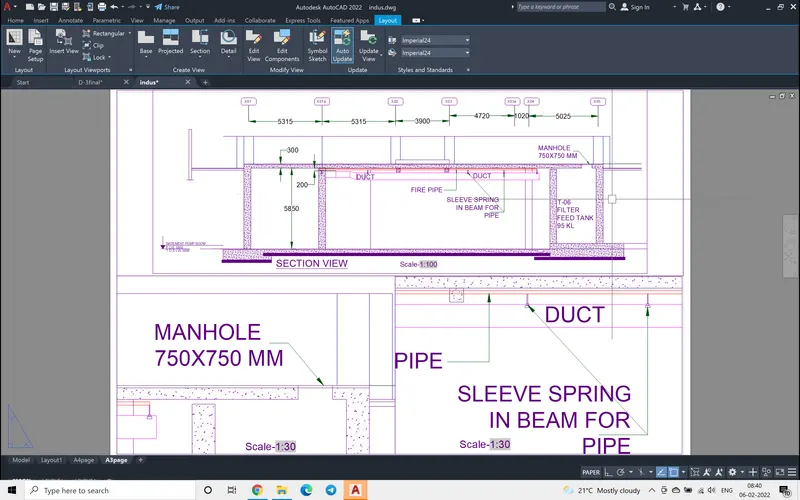
INTRODUCTION: The Induatrial sectional elevational details are shown in 3 different view ports. The Induatrial sectional elevation (1:100)shown as a whole in one view port and two blowup details of the same elevation are shown to the scale 1:30.
PROCEDURE:
Step:1
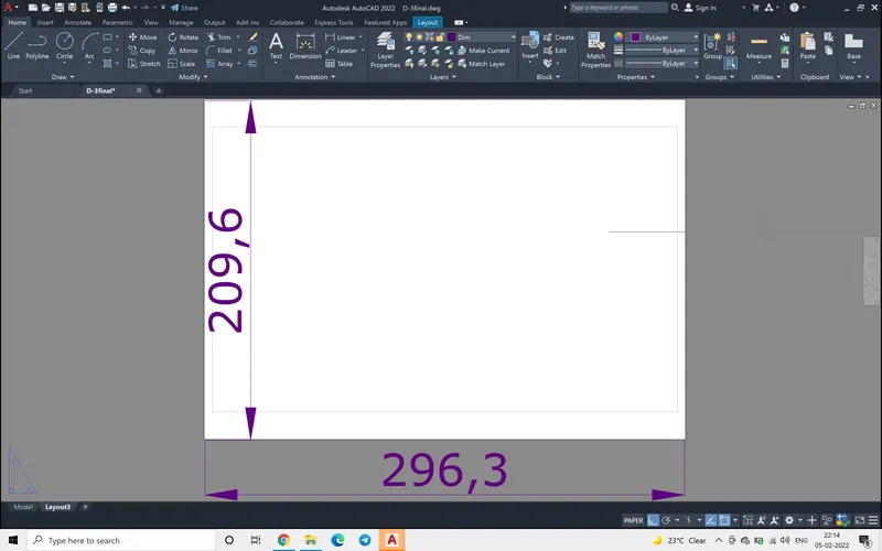
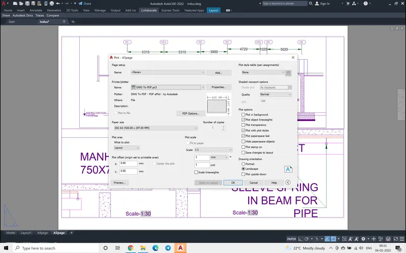
In the challenge the page setup of the layout was done to the A3 paper size( 420x297).
For this on the model space title, right click, rename it as A3page
Step:2
On the A3page layout right click and select page set up manager.
Step:3
In the page set up manager select plotter as DWt to PDF
then here I have choosen scale on the plot 1:1 units.
Step :4
Command viewports was used
Choose the single view port and selected a rectangular space on the A3page.
Double clicking the viewport we can get in to the model space or use MS command to get in to the model.
Then choose command Zoom and Window, select the drawing part with the window, to be shown in the view port.
Now get out of the model space using ps command.
Step 5:
selecting the view port, checking on the drawing aids, scale of the selected view port and chosing 1:100 or what ever the scale we would like to print.
Step : 6
command prompt field command
selecting the object from the list, then the view port, in the viewport the scale of the viewport is choosen. In this only the height of the text to be appeared can also be modified.
initiall it appears like only number 1:100, or 1:30 what ever we have chose. double clicking on the 1:100 we can add text, "scale" to 1:100.
Step :7
In the properties command, or from tab click layout and in layout ribbon tools, clicking lock the viewport, so that there wont be any distrotions in the viewports by accidental selections.
Step 9:
after setting out the viewport, a plot is taken.
an attachment is provided along the procedure in the attachments, please check them.
*******************************************************************************
****************************************************************************
*******************************************************************************
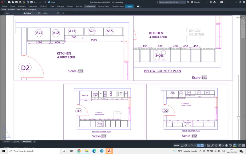
AIM: The aim of this project is to display the kitchen plan in the auto cad layout.
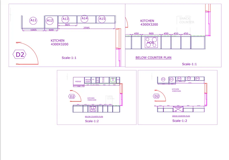
INTRODUCTION: The Kitchen architectural plan details are shown in four different view ports. The kitchen architectural plans above counter and below counter plan are shown in the two different layout plans with 1:2 scale.
The details of the above counter plan and below counter plan are blown up and shown in other two different views ports with scale 1:1.
PROCEDURE:
Step:1
As asked in the challenge the page setup of the layout was done to the A4 paper size( 210x297).
For this on the model space title, right click, rename it as A4setup
Step:2
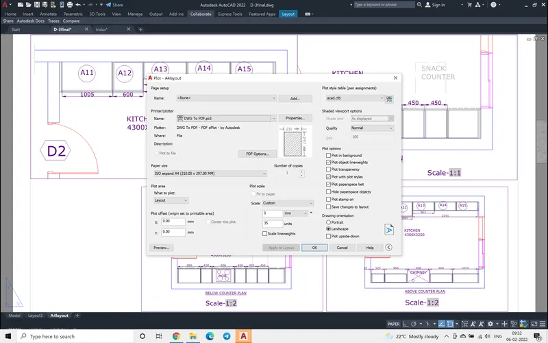
On the A4setup layout right click and select page set up manager.
Step:3
In the page set up manager select plotter as DWt to PDF
then here I have choosen scale on the plot 1:35 units.
Usally it is kept as 1:1. I have tried arranging in 1:1 but it didn't fit.
So tried with many scales from 1:20 to 1:50, but the scale below 1:35 nd 1:30 were good enough.
Wheather this procedure is corect ? I am not sure.
Step :4
Command viewports was used
Choose the single view port and selected a rectangular space on the A4setup.
Double clicking the viewport we can get in to the model space or use MS command to get in to the model.
Then choose command Zoom and Window, select the drawing part with the window, to be shown in the view port.
Now get out of the model space using ps command.
Step 5:
selecting the view port, checking on the drawing aids, scale of the selected view port and chosing 1:2 or what ever the scale we would like to print.
Step : 6
command prompt field command
selecting the object from the list, then the view port, in the viewport the scale of the viewport is choosen. In this only the height of the text to be appeared can also be modified.
initiall it appears like only number 1:2, or 1:1 what ever we have chose. double clicking on the we can add text, "scale" to 1:1.
Step :7
In the properties command, or from tab click layout and in layout ribbon tools, clicking lock the viewport, so that there wont be any distrotions in the viewports by accidental selections.
Step 9:
after setting out the viewport, a plot is taken.
an attachment is provided along the procedure in the attachments, please check them.