Creating a Floor plan, Footing detail and Isometric view using AutoCad
Aim: To draw the following using Autocad.
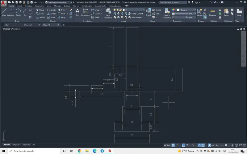
1. To draw section of footing, basement masonry and stairs.
Step:1
* In the command prompt type units and select decimal unit.
Step 2: In the command prompt "Limits" is used and lower limits as 0,0 and upper right corner limit as 10,10 is set
Step 3: Using Grid command, the appearence of grid is restricted to the limits set.the options chosen are "Limits" and "No" to apply the grid only to the limits set.
Step 4:
* In the command prompt type poly line(alias PL)
* In the command prompt specifying the start point, here i just clicked on thee screen.
* In the command prompt type 0.9 by just moving the cursor in that direction.
* In the command prompt typing thickness 0.25 by keeping Ortho on and by moving cursor parallel to Y axis.
* In the command prompt giving the offset dimension ((0.9-0.5/2)=0.2), repeating the one side of the footing till the basement level.
*Once the half of the footing is done(I finished the left half first), in the command prompt using the command Mirror, and the typing No, to not to erase the original, entire footing is drawn.
* Dimensions are annotated using command DIMLIN.
* Dimension style is edited to choose the drawing, using the command DIMSTY.
***************************************************************************************************
Aim: To draw the following using Autocad.
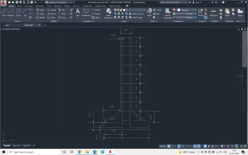
1. To draw section of sloped footing and reinforcement details.
Step:1
* In the command prompt type units and select decimal unit.
Step 2: In the command prompt "Limits" is used and lower limits as 0,0 and upper right corner limit as 10,10 is set
Step 3: Using Grid command, the appearence of grid is restricted to the limits set.the options chosen are "Limits" and "No" to apply the grid only to the limits set.
Step 4:
* In the command prompt type poly line(alias PL)
* In the command prompt specifying the start point, here I just clicked on thee screen.
* In the command prompt type 1 by just moving the cursor in that direction.
* In the command prompt typing thickness 0.15 by keeping Ortho on by moving cursor parallel to Y axis.
* In the command prompt giving next point as 0.38,0.25 to get a sloped line.
*Once the half of the footing is done, in the command prompt using the command Mirror, and the typing No, to not to erase the original, entire footing is drawn.
* Command PL is used to draw the steel reinforcement and stirrups are drawing by using command 'copy' and 'multiple' at spacing 0.2.
* Dimensions are annotated using command DIMLIN.
* Dimension style is edited to choose the drawing, using the command DIMSTY.
************************************************************************************************
Aim: To draw the following using Autocad.
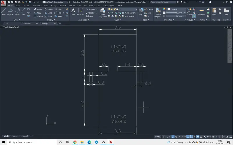
2. To draw plan of house.
Step:1
* In the command prompt type units and select decimal unit.
Step 2: In the command prompt "Limits" is used and lower limits as 0,0 and upper right corner limit as 10,10 is set
Step 3: Using Grid command, the appearence of grid is restricted to the limits set.the options chosen are "Limits" and "No" to apply the grid only to the limits set.
Step 4: The dimensions of the plan which are shown in the following figure are drawn using command PL.
* The coordinate system adopted is, by moving the cursor in the direction required and giving the magnitude in the command prompt. Here ORTHO ON is used so that the movement of cursor is restricted to only 90 degrees.
* Dimensions are annotated using command DIMLIN.
* Dimension style is edited to choose the drawing, using the command DIMSTY.
*********************************************************************************************
Aim: To draw the following using Autocad.
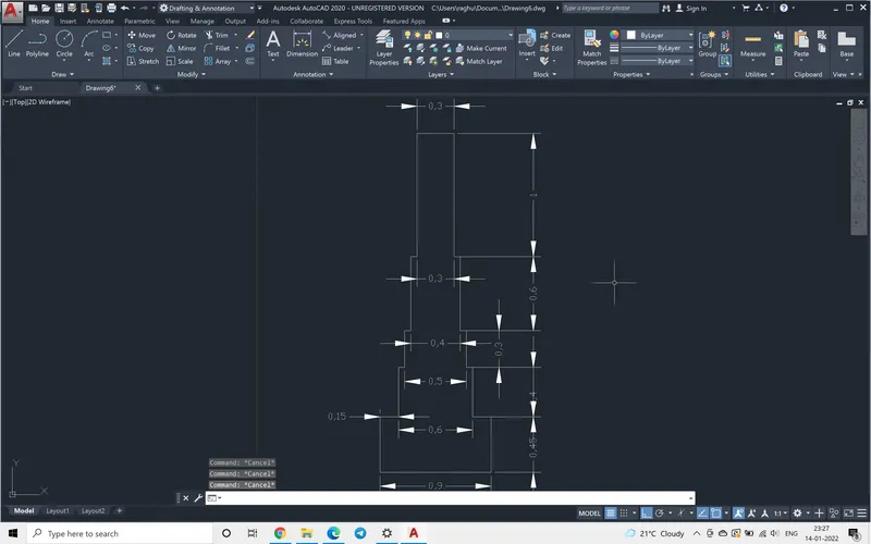
2. To draw elevation of multi pedestal footing or stepped footing.
Step:1
* In the command prompt type units and select decimal unit.
Step 2: In the command prompt "Limits" is used and lower limits as 0,0 and upper right corner limit as 10,10 is set
Step 3: Using Grid command, the appearence of grid is restricted to the limits set.the options chosen are "Limits" and "No" to apply the grid only to the limits set.
Step 4: The dimensions of the plan which are shown in the following figure are drawn using command PL.The offeset of the pedestals are obtained as following (0.9-0.6)/2=0.15, similarly all otherr offset can be obtained.
* The coordinate system adopted is, by moving the cursor in the direction required and giving the magnitude in the command prompt. Here ORTHO ON is used so that the movement of cursor is restricted to only 90 degrees.
*Once the half of the footing is done, in the command prompt using the command Mirror, and the typing No, to not to erase the original, entire footing is drawn.
* Dimensions are annotated using command DIMLIN.
* Dimension style is edited to choose the drawing, using the command DIMSTY.
*********************************************************************************************
Aim: To draw the following using Autocad.
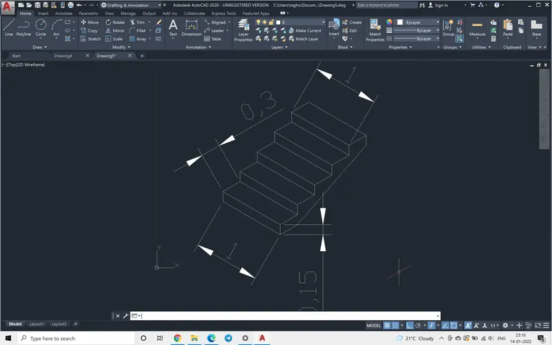
2. To draw stair case using Isometric view.
Step:1
* In the command prompt type units and select decimal unit.
Step 2: In the command prompt "Limits" is used and lower limits as 0,0 and upper right corner limit as 10,10 is set
Step 3: Using Grid command, the appearence of grid is restricted to the limits set.the options chosen are "Limits" and "No" to apply the grid only to the limits set.
Step 4: Using the command "DS", to change the snap mode to isometrc view. Using the command Func+F5 for changing the isometric views like isometric left, isometric top, isometric right.
* The coordinate system adopted is, by moving the cursor in the direction required and giving the magnitude in the command prompt. Here ORTHO ON is used so that the movement of cursor is restricted to only 90 degrees.
* When Isometric left is on, a rectangle of 1x0.15 dimension is drawn, then changing view to Isometric right the step portion parallel to this view is drawn, then chnaging view to top, the other portion of the drawing is completed.
* Dimensions are annotated using command DIMLIN.
* Dimension style is edited to choose the drawing, using the command DIMSTY.
********************************************************************************************************
Aim: To draw thw following using Autocad.
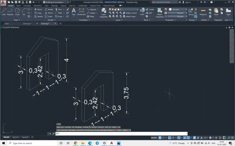
2. To draw Gabled wall with opening using Isometric view.
Step:1
* In the command prompt type units and select decimal unit.
Step 2: In the command prompt "Limits" is used and lower limits as 0,0 and upper right corner limit as 10,10 is set
Step 3: Using Grid command, the appearence of grid is restricted to the limits set.the options chosen are "Limits" and "No" to apply the grid only to the limits set.
Step 4: Using the command "DS", to change the snap mode to isometrc view. Using the command Func+F5 for changing the isometric views like isometric left, isometric top, isometric right.
* The coordinate system adopted is, by moving the cursor in the direction required and giving the magnitude in the command prompt. Here ORTHO ON is used so that the movement of cursor is restricted to only 90 degrees.
* When Isometric left is on, a rectangle of 3x0.3 dimension is drawn, then changing view to Isometric right and finishing the other portion parallel to this view. Here two gabled walls with two different max height at centre are varied , one is 4 and other is 3.75.
* Dimensions are annotated using command DIMLIN.
* Dimension style is edited to choose the drawing, using the command DIMSTY.
********************************************************************************************************