Creating 3D Isometric view of various structural elements in AutoCAD
AIM: The aim of this challenge is to apply the 3d modelling tools to make the following model. This particular task helped me to understand the procedure and tricks teo make a 3D model of a plan.
INTRODUCTION: The following plan is drawn either in 2D plane or 3D plane, it is easy to draw the 2D and then move to 3D working space. But here I have drawn the plan directly on the 3D working space. Once the plan is done that is all the walls and windows. The window lines with in the wall are not necessary for extrusion, therefore they are removed just a rectangle at the window location is left.
Then by using presspull, the bottom floor, the walls of required height are obtained. At the window locations the walls are projected till the sill level of the window and then again from top of the window to roof.
After the walls are projected or extruted, they act like different entities, by using union command all are converted to single entity.
Once the bottom floor and the walls are done, then the roof slab is press pulled and copied on to the roof location.
After that the UCS command is used and its location and direction is changed, now the X-Y plane are parallel to the wall, and Z axis is parallel to the thickness of the wall.
Now a rectangle of the size of the window is drawn and a 3D model of it made. the wooden outer frame was considered as 1.5", inner frame 1" and the glass panes thickness 0.25".
Then the inbuilt AutoCad library has different materials of building and it is souced from command MAT. The required materials re chose and drag and dropped to actual 3D model.
The following sequence of images show the working process followed in making the 3D model.
PROCEDURE:
Step 1: At the command prompt Units commands is used and the units are set to Engineering, precision to 0',0".
Step 2: Then the command Limmax is used and set the limit maximum to 15',15'.
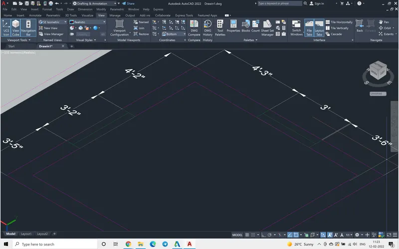
Step 3: Using rectangle command the outer rectangle is drawn, then offset command was used to a offset distance 9".
Step 4: Using D the dimension style was set to suit the drawing.
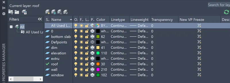
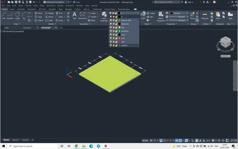
Step 5: The drawing also has different layers, the layer command was used and the each component of the building were given separate layer, as shown below.
The following image shows the fully drawn plan and annotated with dimensions.
Step 6:
Here the bottom slab was press pulled to 4" thick keeping the bottom slab layer as current layer. After that this layer was put off and locked.
Step 7:
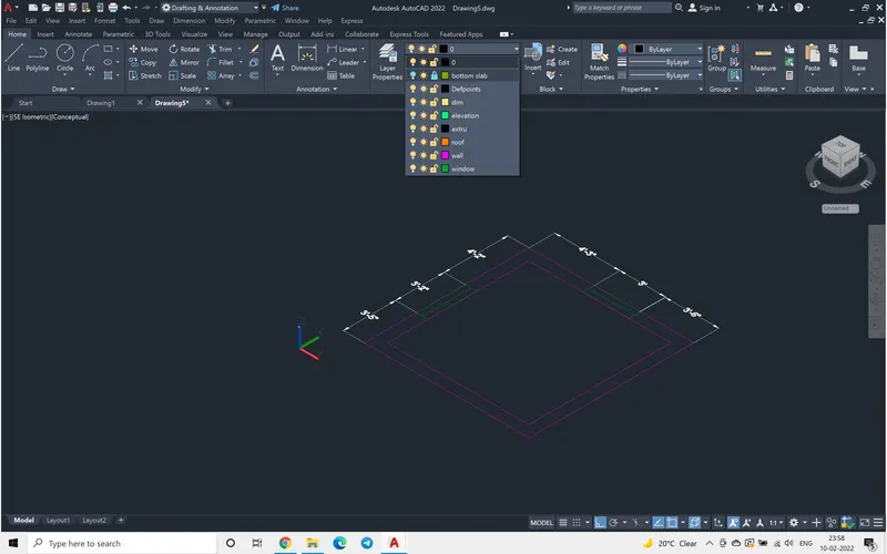
The following image show that the bottom slab is not visible.
Step 8:
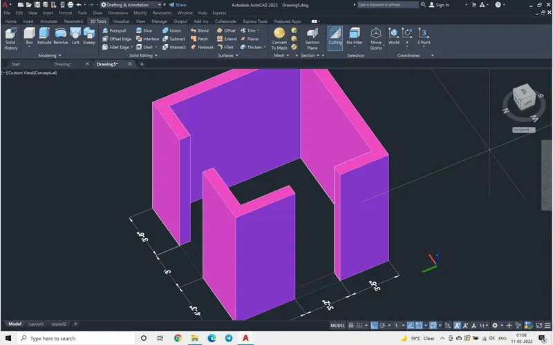
Now the walls are press pulled using the command presspull to 10' height.
Step 9:
The wall below the window and above the wall are done separately and copied to the position. Then Union command is used to make them in to a single entity.
Step 10:
Window are drawn as per specification, using rectangle and offset commands,
Step 11:
Using UCS command and shifting it and making X-Y plane prallel to window, then the
Step 12:
Using Press pull, the 3D window is drawn.
Group command was used to make them as one entity and it will be easy to work with them.
Step 13:
Using the command copy the window is copied.
Step 14:
Using The command 3Drotate the the window was ratated and copied to the other wall.
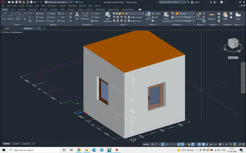
The following model is achieved.
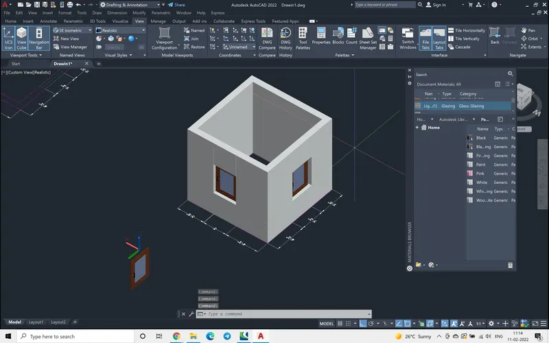
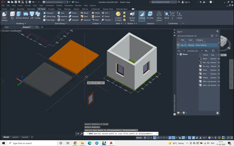
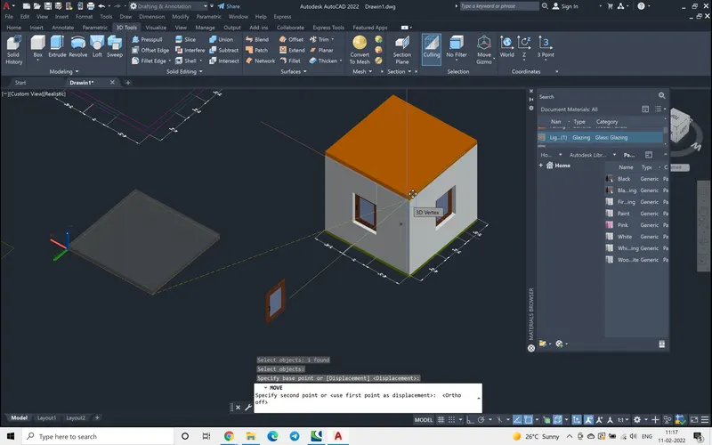
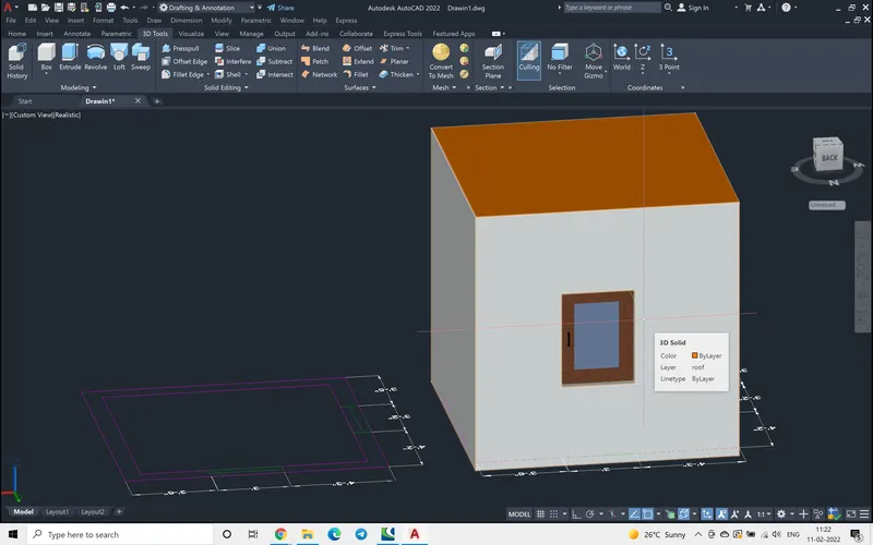
****************************************************************************************************************
AIM: The aim of this challenge is to apply the 3d modelling tools to make the following model. This particular task helped me to understand the procedure and tricks teo make a 3D model of a plan, which is having ground plus 3 fllor.
INTRODUCTION:
The following plan is drawn either in 2D plane or 3D plane, it is easy to draw the 2D and then move to 3D working space. But here I have drawn the plan directly on the 3D working space. Once the plan is done that is all the walls and windows. The window lines with in the wall are not necessary for extrusion, therefore they are removed just a rectangle at the window location is left.
Then by using presspull, the bottom floor, the walls of required height are obtained. At the window locations the walls are projected till the sill level of the window and then again from top of the window to the bottom of the next floor window.
After the walls are projected or extruted, they act like different entities, by using union command all are converted to single entity.
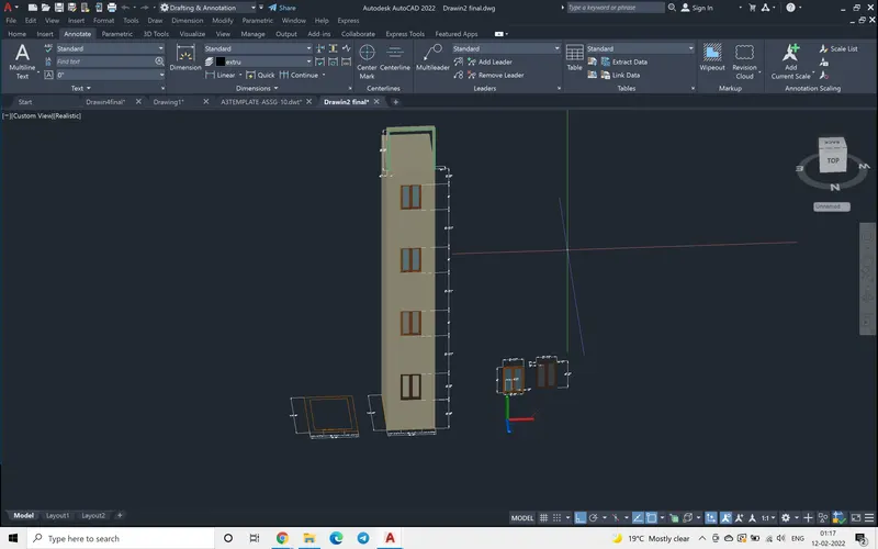
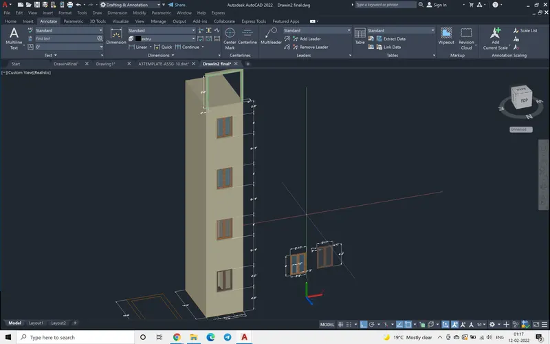
Once the bottom floor and the walls, windows up to third floor are done, the small portion above the top floor window is done, then the roof slab is press pulled and copied on to the roof location.
After that the UCS command is used and its location and direction is changed, now the X-Y plane are parallel to the wall, and Z axis is parallel to the thickness of the wall.
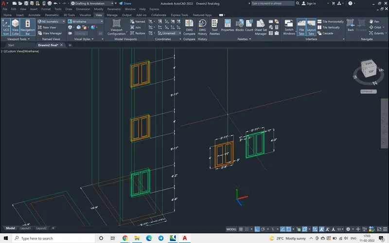
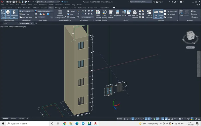
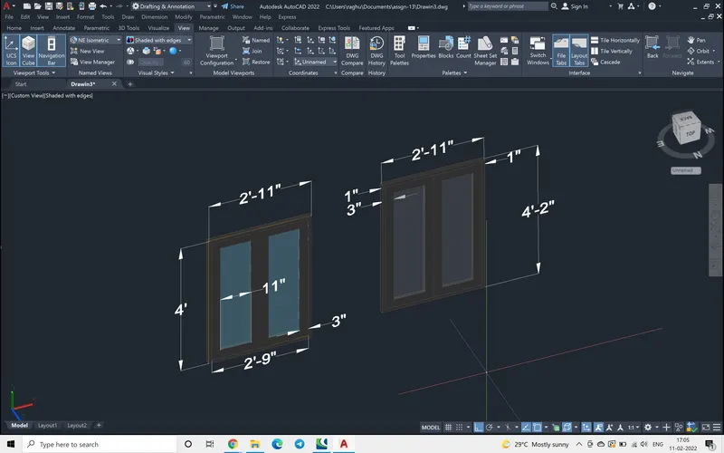
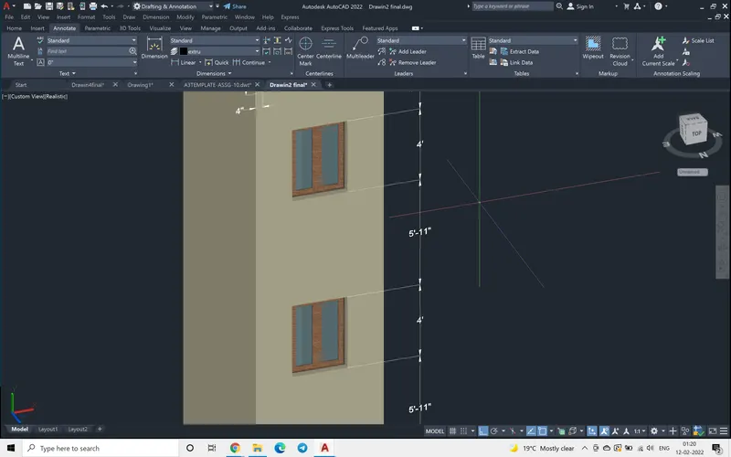
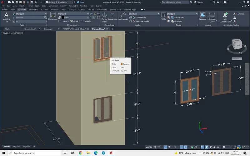
Now a rectangle of the size of the window is drawn and a 3D model of it made. the outer wooden frame was considered as 1.5", inner frame 1" and the glass panes thickness 0.25". Here there are two types of windows are used, one is 4' height and the other one is 4'-2". The bottom most window is 4'-2" ht and the remaining are 4'.
Then the inbuilt AutoCad library has different materials of building and it is souced from command MAT. The required materials re chose and drag and dropped to actual 3D model.
The following sequence of images show the working process followed in making the 3D model.
PROCEDUE:
Step 1: At the command prompt Units commands is used and the units are set to Engineering, precision to 0',0".
Step 2: Then the command Limmax is used and set the limit maximum to 15',40'.
Step 3: Using rectangle command the outer rectangle is drawn, then offset command was used to a offset distance 9".
Step 4: Using D the dimension style was set to suit the drawing.
Step 5: The drawing also has different layers, the layer command was used and the each component of the building were given separate layer, as shown below.
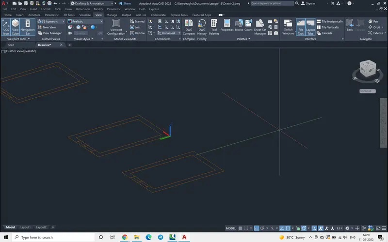
The following image shows the fully drawn plan.
Step 6:
Here the bottom slab was press pulled to 4" thick keeping the bottom slab layer as current layer. After that this layer was put off and locked.
Step 7:
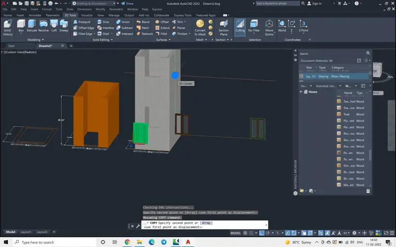
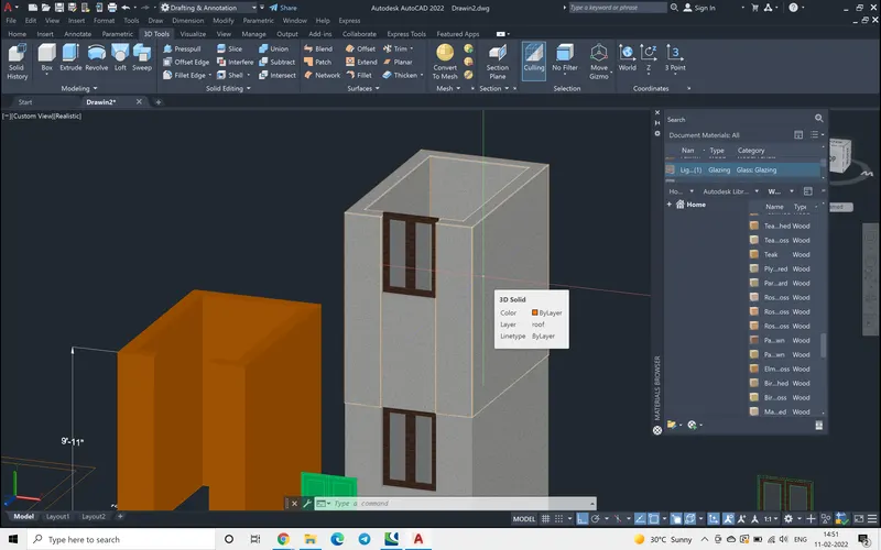
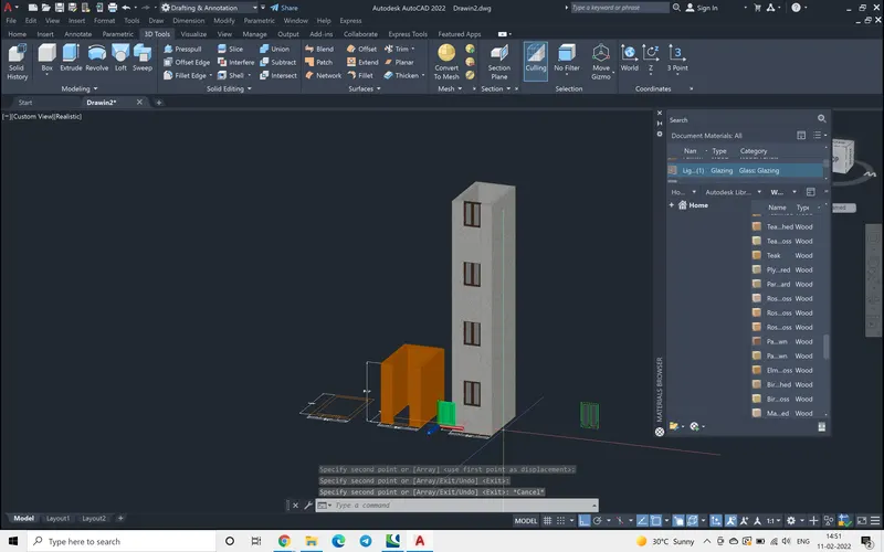
Now the walls are press pulled using the command presspull to 8'-8" height, the next extrusion height 9'-11" is repeted twice. The orange coloured layered walls displayed in the below image is copied twice.
Step 8:
The wall above the window is done separately and copied to the position. Then Union command is used to make them in to a single entity.
Step 9:
Window are drawn as per specification, using rectangle and offset commands,
Step 10:
Using UCS command and shifting it and making X-Y plane prallel to window, then the
Step 11:
Using Press pull, the 3D window is drawn.
Group command was used to join all the entites of window so that it will be easy to copy it.
Step 12:
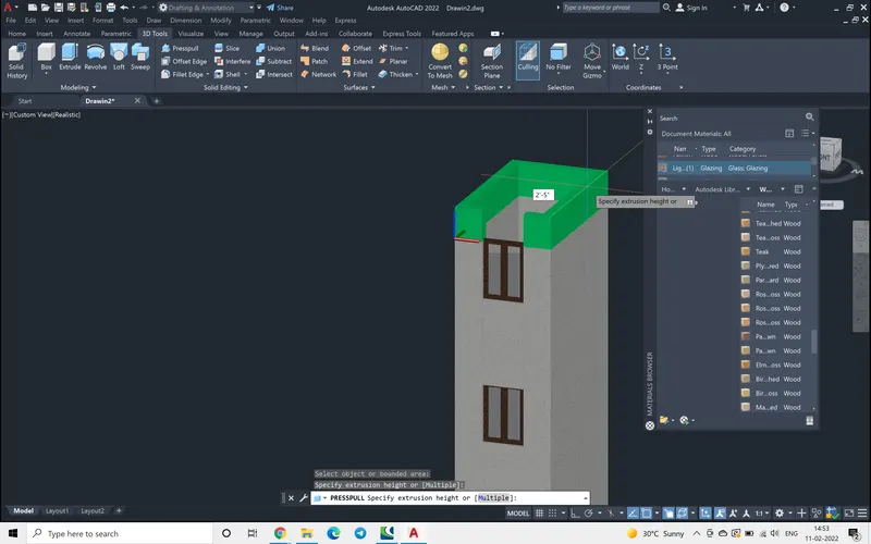
Using the command copy the window is copied.
Step 13:
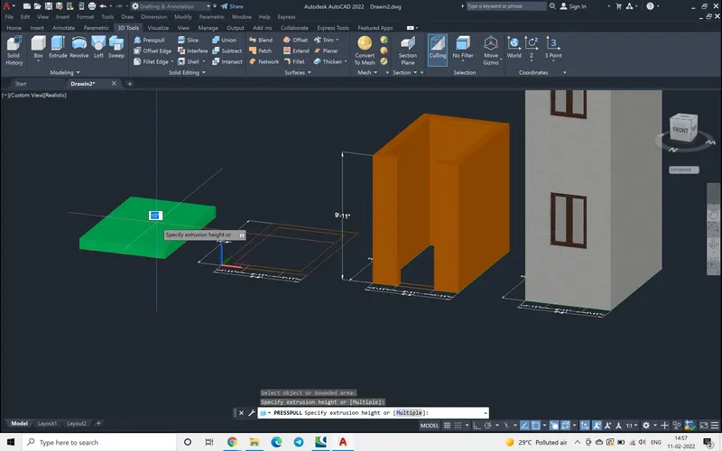
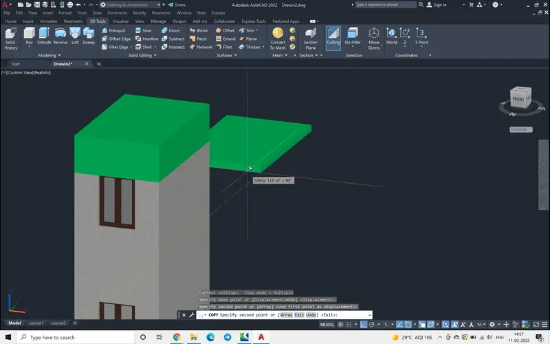
the roof slab is press pulled and copied on to the roof location.

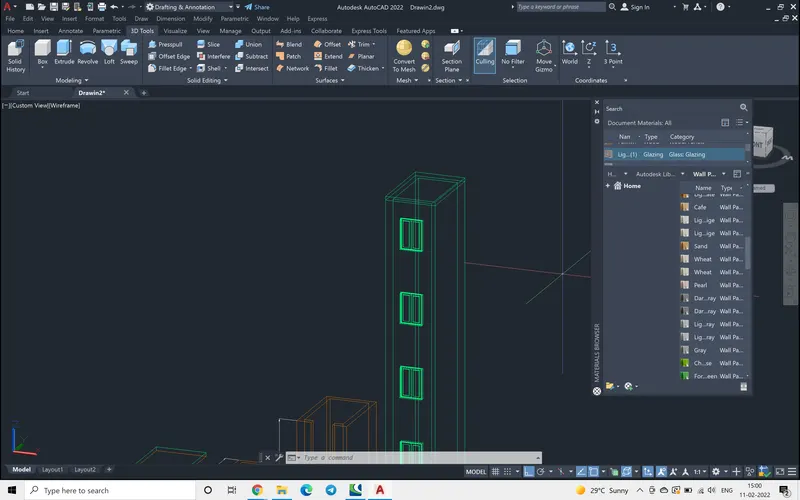
Step 14:
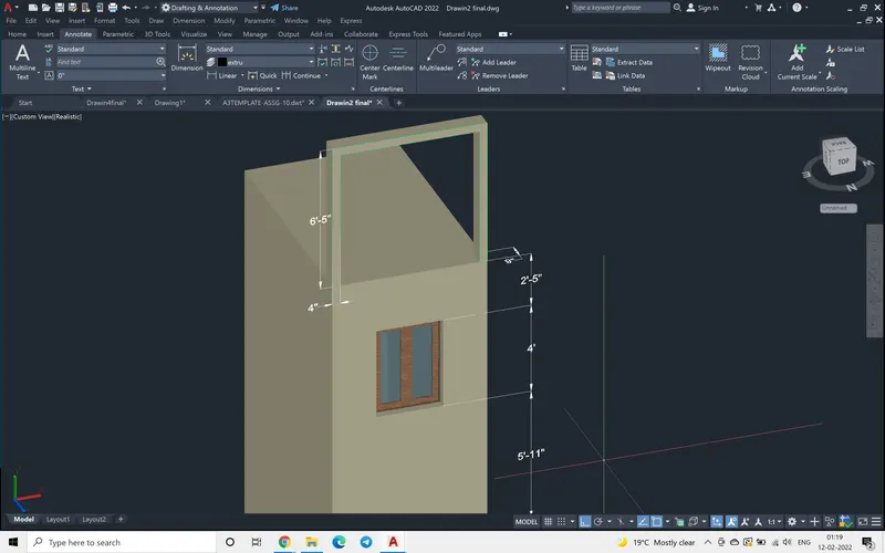
There is a architectural details at the roof that is drawn first by changing the UCS position and then press pulled.
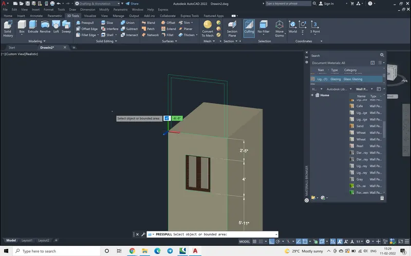
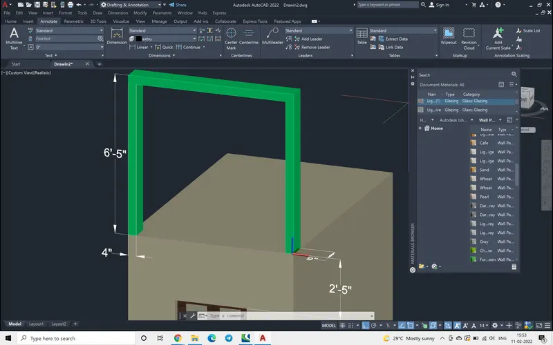
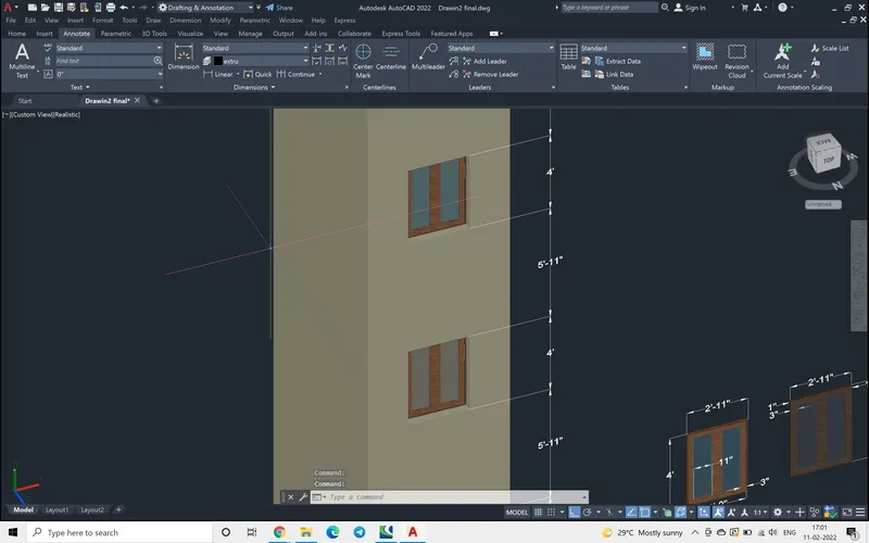
Step 15:
Using D command, the dimension style is set the suit the draing.
The following are the two different window models.
**************************************************************************************************************
AIM:
The aim of following task is to undertand the procedure to draw a stair case and to develope a detailed 3D model of the staircse.
INTRODUCTION: Any staircase the sectional elevation has to be drawn first to develope a 3d model.
To draw the sectional elevtion the UCS is changed ott his direction.
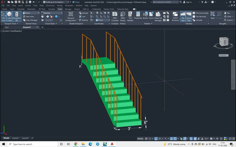
Initially the rise 6" and tread 1'are drawn, and are copied to the required number of steps.
THe ballust slab is drawn, then all the steps, landing and ballust slab are joined and they are now one enitity.
Now the stairs are press pulled to the given dimension 3'.
The railings are drawn and copied to the requied position then using command sweep the railing is drawn the images shown below show the working procedure followed.
PROCEDURE:
Step 1: At the command prompt Units commands is used and the units are set to Engineering, precision to 0',0".
Step 2: Then the command Limmax is used and set the limit maximum to 10',20'.
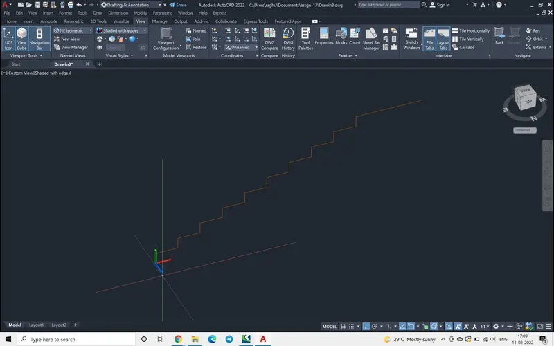
Step 3: The ballust slab is drawn
using extend command the slab is extended, the following images show that.
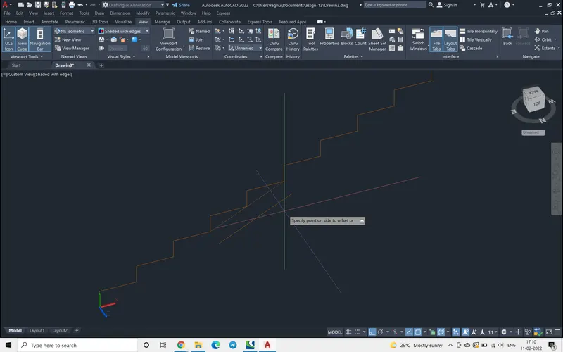
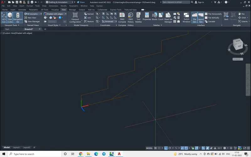
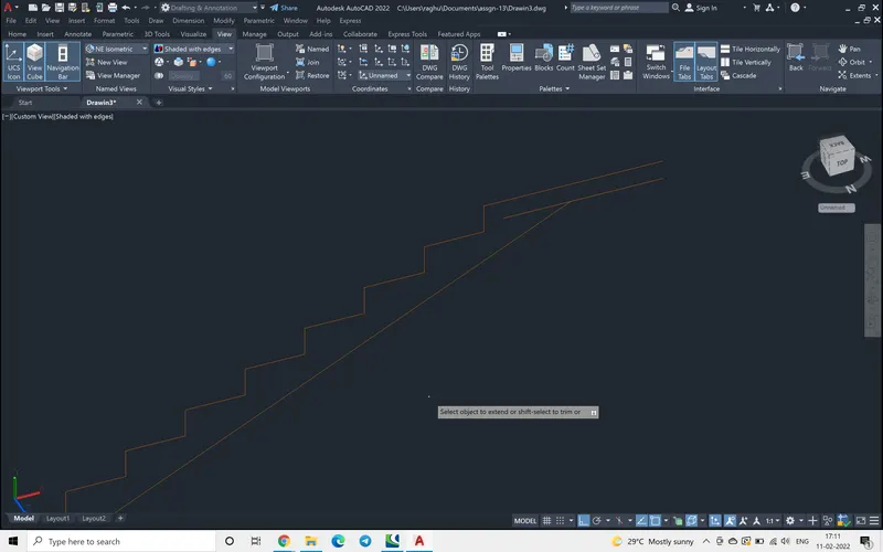
Step 4: using command join all the steps, landing and ballust are made into a single entity.
The following image show that all the components are acting together
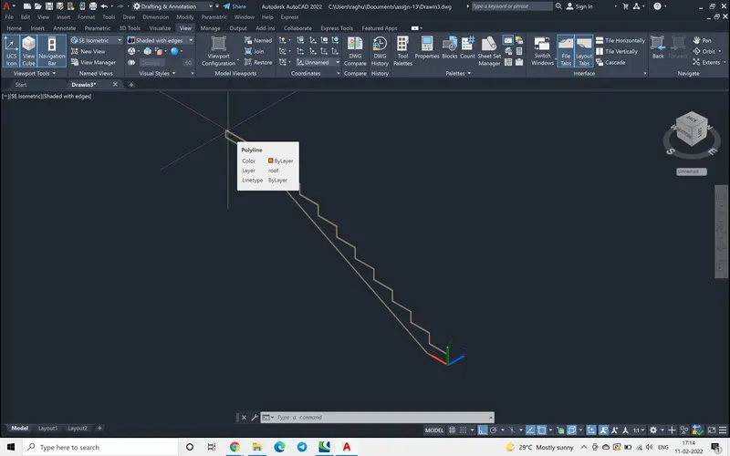
Step 5:
Command press pull was used to a thickness for 3', the following image show that.
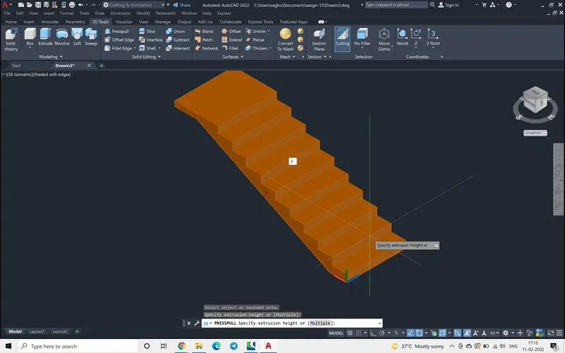
The following image show the conceptual image.
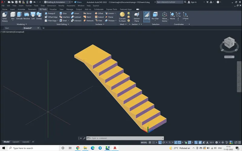
Step 6:
The rail posts are drawn and copied at required position
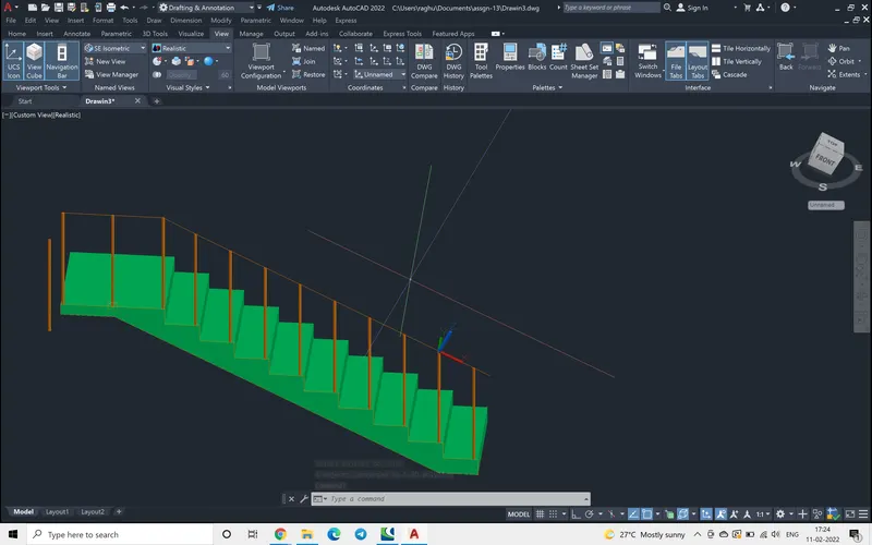
Step 7:
command sweep is used to draw the hand railing,
the railing is of circular shape, a small circle at the starting of the sweep locaion is drawn, then the path is given to complete the railing.
this is all possible when UCS is shifted.
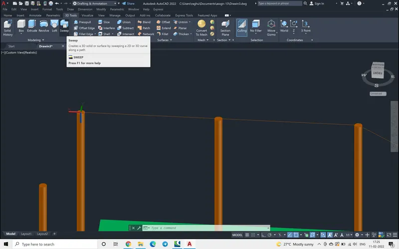
Step 8:
The following image show the one side of the railing is done and the same is grouped.
Step 9:
Group command was used to join all the entites of railing so that it will be easy to copy it.
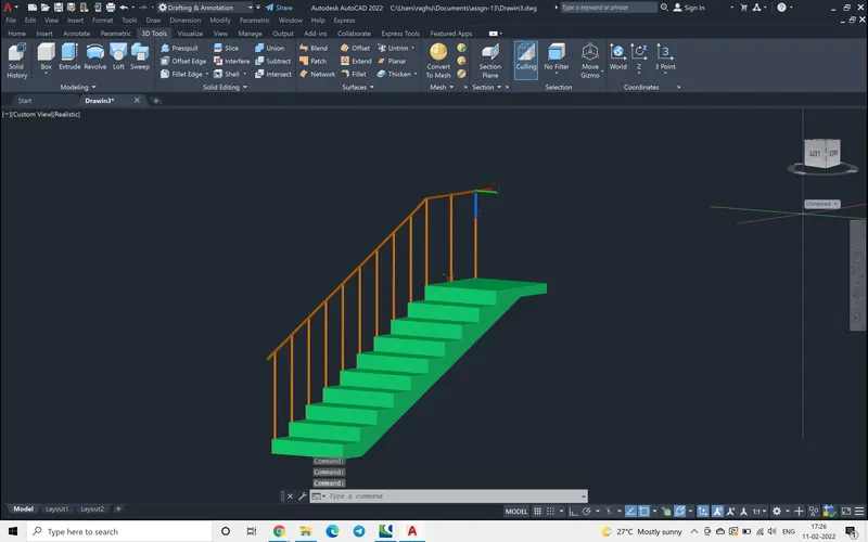
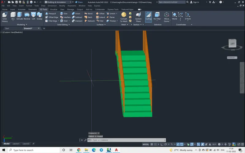
The following 3D model of stair is achieved.
************************************************************************************************************
AIM: The aim of this task is to know how the 3D modelling of footing and wall masonary section details are done.
INTRODUCTION: IN this modelling, initially UCS was moved to draw the sectional elevation in 2D, then the press pull command was used to make the 3D model.
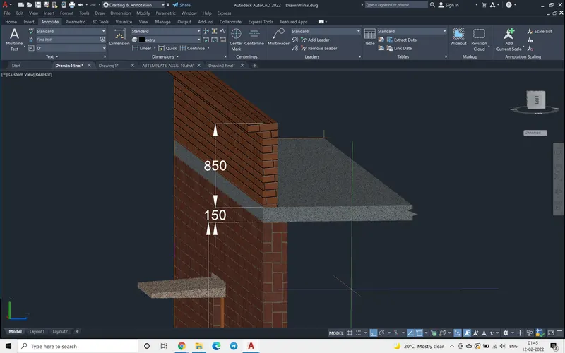
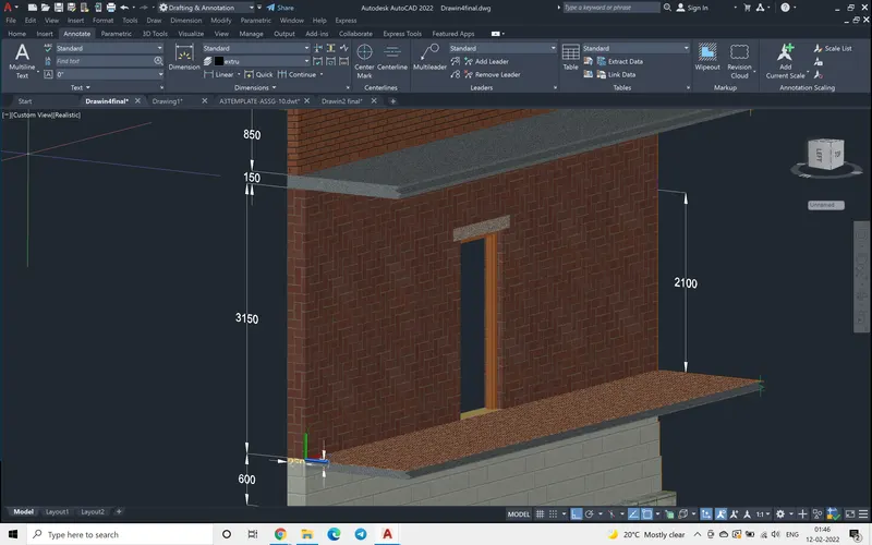
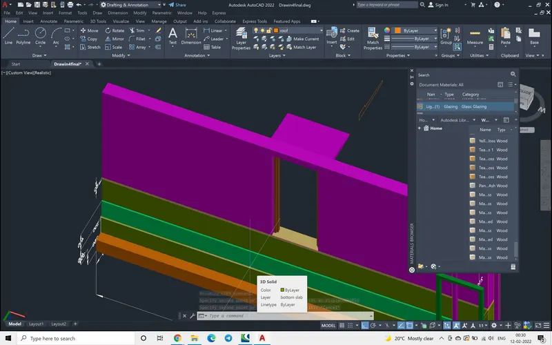
There was an opening left for Door. A chajja , parapet walls were also added. The masonary below ground was assigned different compared to above the ground. The Auto Cad library has prefined materials. Using MAT command the library can be seen and the materials were assigned to the 3D model.
The following images show the procedure followed to make this 3D model.
PROCEDURE:
Step 1:
At command prompt the command Units were used and Decimal was selected with precision 0.
Step 2:
Limmax commad was used and limits were set as 5000,5000
Step 3:
UCS was chose in such a way that the cross sectional elevation can be drawn, X-Y plane is parallel to cross section.
Step 4:
Using rectancle commnads the separate rectangles were drawn one above the other.
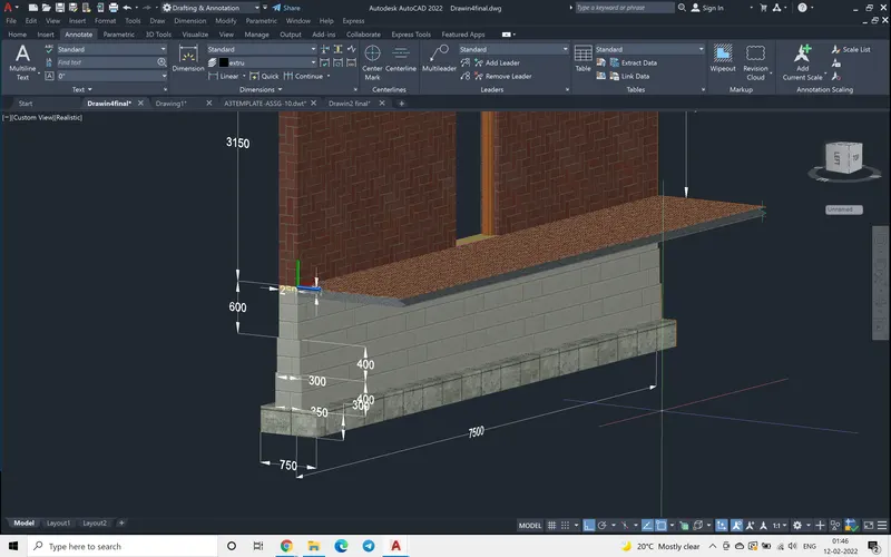
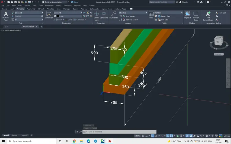
the bottm rectangle dimension 750X300
then 350 x 400, 300x400, 250x600
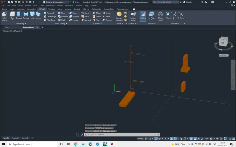
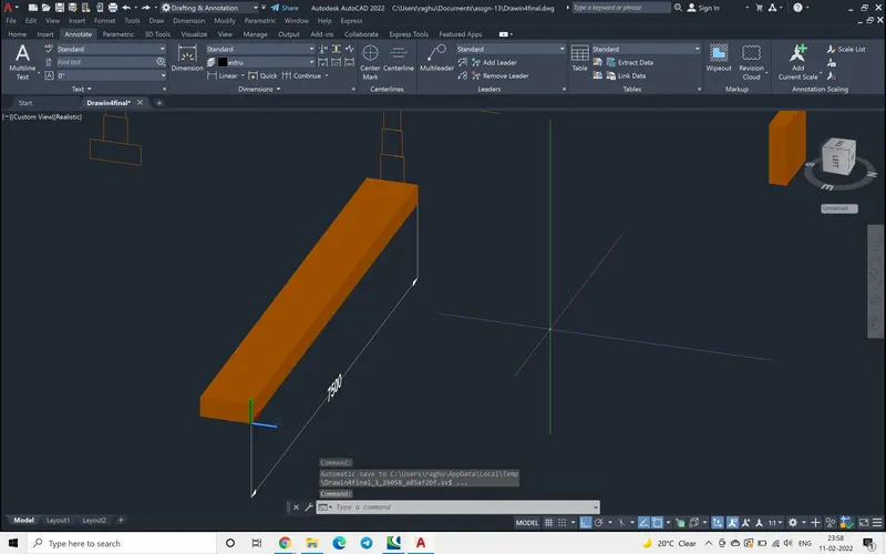
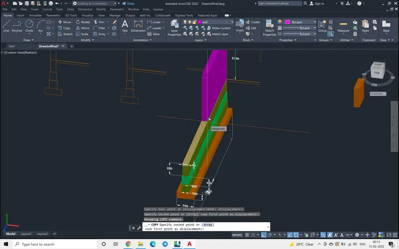
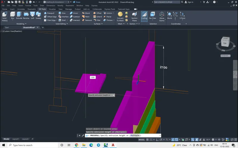
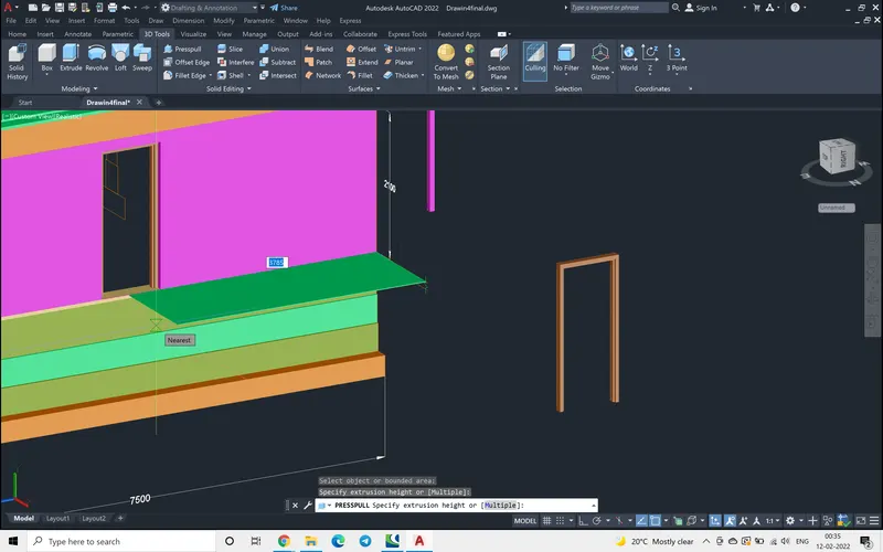
and then the wall of 250x 2100 and then press pulled to 7500.
Step 5: Then the chajja is drawn above the door using polyline.
Step 6: then the wall above the chajja and the parapet wall sections were drawn.
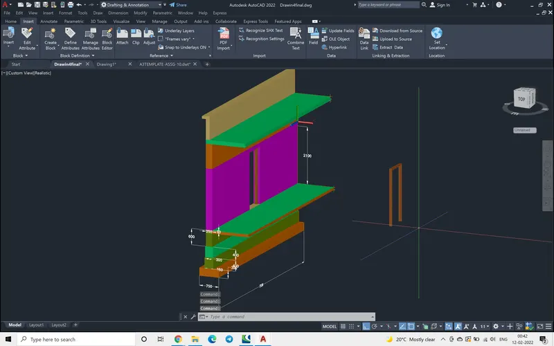
Step 7: After drawn individual elements as rectangles, the presspull command was used and each rectanle was extruded, the same is shown the images.
Step 8:
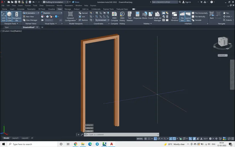
The door frame was drawn using sweep command
The path is the outer line of the door, and the cross section of the door has to be drawn at the any end of the frame, as shown in the image,
sweep commnd is applied it asks for the section and then path, selecting them sequently the frame can be easily drawn.
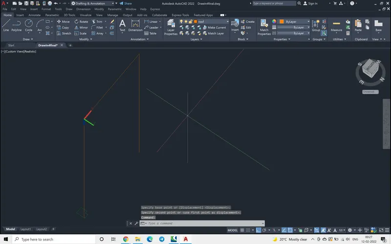
The following image show how the 3D model of the door frame would look after appliying sweep command.
Step 9: Using copy command the frame wa shifted to the cente of opening.
Step -10:
The cross sections have the slab and roof, shifting the UCS to these locations we ca press pull them. these slabs were given brekline command in 2D, the same can be seen in 3D model also.
Step 11:
Using D ccommand the dimension style was set to suit the drawing.
Using dimension linear the dimensions were annotated, here the dimensioning i possible only on X-Y plane, again if on th Z-axis direction we need to annototate the dimension, the X-Y plane has to be made parallel to that direction.
Step 12:
Using MAT command again the the materials were chose from the Auto cad library and annotated to the sections.
The following image shows the details materials used.
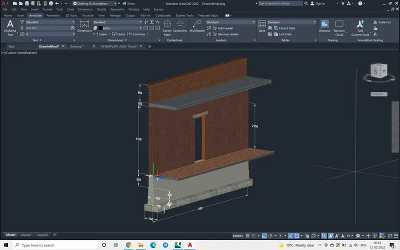
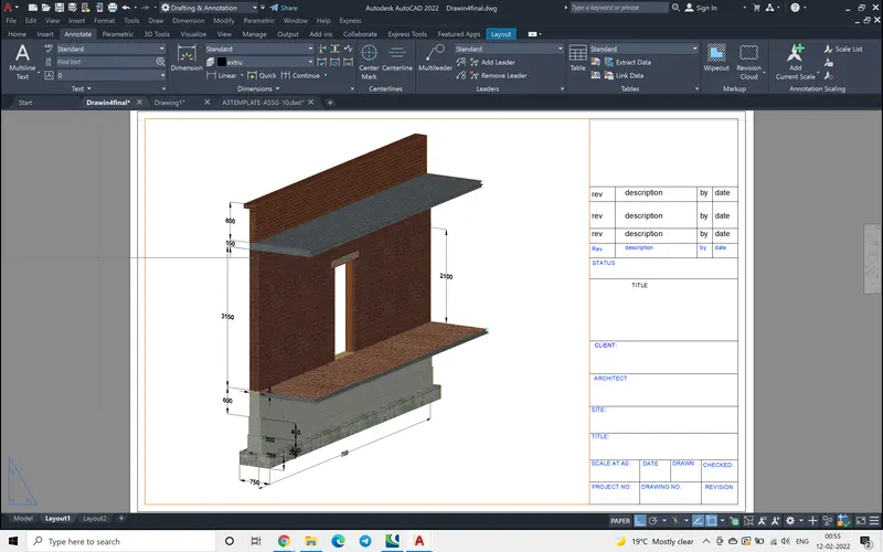
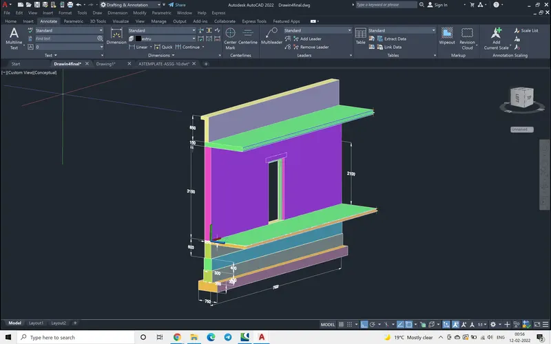
The following Image shows the conceptual image.
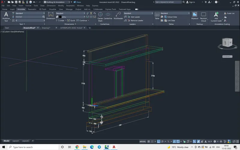
The following is the wireframe image.
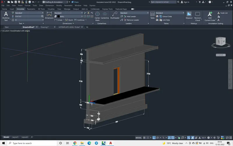
The following is the shaded with edges images.
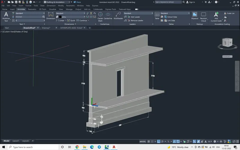
The following image is the shades of grey
The following is the realistic image.
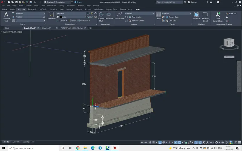
The other side of the wall image.
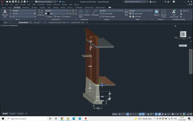
The following are the blown up images.