Project 2_Creating a 3D rendered model for a Residential Building in AutoCad
AIM: The aim of this project is to understand the 3D modelling and to develope the 3D model of any house.
INTRODUCTION:It is very important to understand the accuracy of dimensions in any autocad drawing. This tool has vast applications in engineering and 3D modelling is very useful in understanding the protype of the project which is goin to come up in real. It is always easy to understand the different features providedd in any project by solid modelling.
THe 3D model also helps in understanding the conflicts between any provisions provided in the project.
The 3D model helps to visualize the upcoming project easily by any layman.
The tools which are provided by the Auto cad are very easy and effective to draw a 3D model.
The inbuilt material tools which are provided in the tool are very easy to apply to the project.
The different views provided by the tool helps to visualize the building in various directions.
The tools like extrude, press pull, box were very easy to apply and a good quality 3D model could be developed.
With the help of 3D rendering, very effective images of the upcoming projects can be produced.
THe visualize ribbon has many tools to produce a rendered image to different qualities like, low , medium, high with different resolutions provided.
On the whole it was a very good experience to underatsnd the 3D tools and its application in producing the 3D images of the projects.
The current project is my home which is coming up in my native town.
PROCEDURE:
The following images show the step by step procedure followed to develope the 3D model.
Step1:
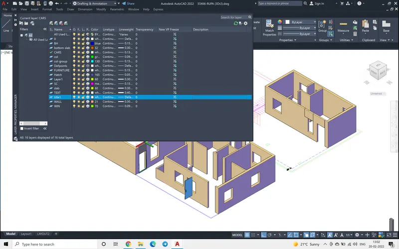
INitially the layers were set to suit the each component of the project.
The below picture shows the image of layers used in the project.
Step2:
UNits command was used
The units was choose as engineering
with precision 0',0"
Step 3:
Limmax was used
the limits were set as 100'x100'
Step 4:
The plan was drawn using polyline command,
Then offset commands were used to draw the external walls with 9" thick and the internaal walls with 6"
Step 5:
The doors and windows commands were draw and added to the plan.
to draaw the windows rectangle command was used.
Step 5:
ONce the plan was ready, the ucs was changed to isometric vies.
Step 6:
The the command 3D box was used to draw the walls , the height os the walls was used as 10.5' and the wall height below the windows were projected till 3'.
The following image shows this.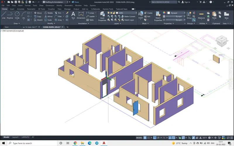
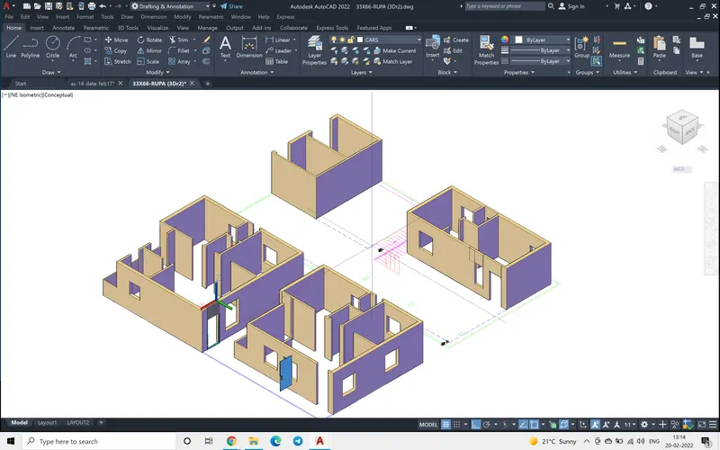
Step 7:
The roof slabs and the bottom slab were drawn.
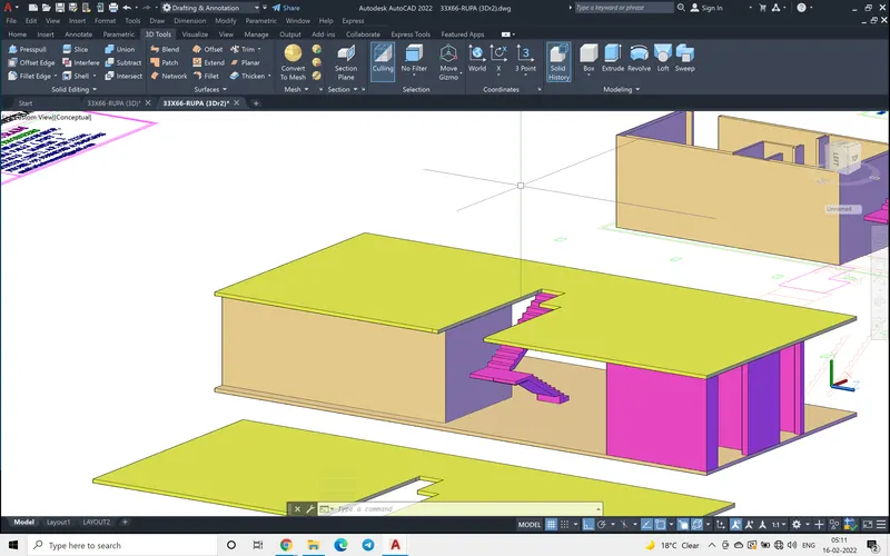
Step 8:
The wall layer was put off and stairs were srawn
to draw the stairs the ucs was changed and it was extuded to a distance of 2'11"
there is a lift provision behind the stairs.
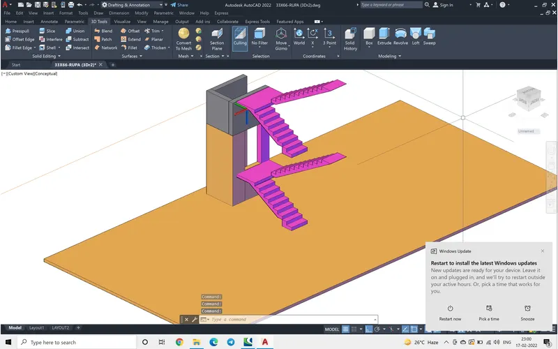
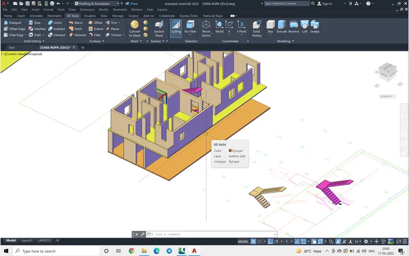
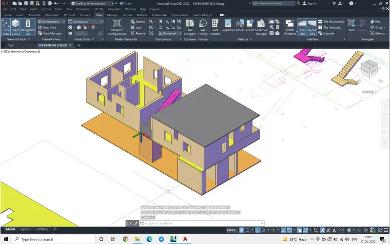
Step 9: The top roof slab was drawn as shown in the below image. command box was used with thickness 5".
Step 10:
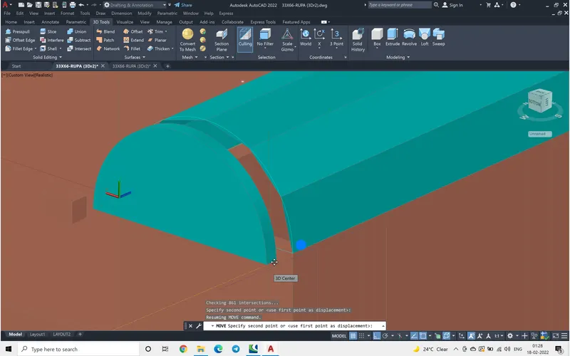
Initially a pyramid was drawn, but later I changed to to a curved surface,
The head room was drawn, the modelling ribbon was used to select the surface command to draw the surface between two curved lines.
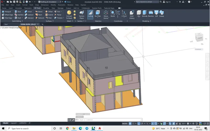
THe following image show the curved surface.
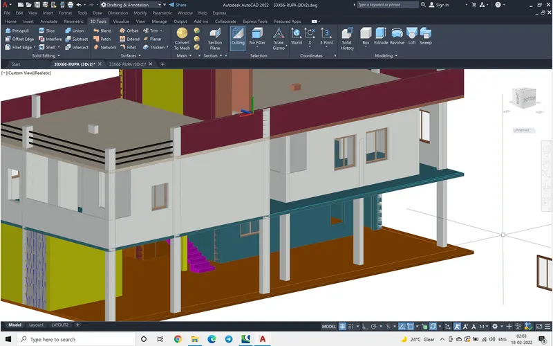
Step 11:
The material command was used and the wall colour, and different colours were chose to different components andd clear glass was used where ever glass was used.
Step 12:
In the visualize ribbon the command set camera command was used to position the camera using the top view of the model.Three cmeras were set.
Then in the isometric view after highlighting the gizmos, the camera was adjusted and the range or the focus of the camera was also adjusted.
Step 13:
The Sky background and the illumination was selected
Then full shadow was put on
Sttep 14:
The quality of rendering was checked to high, then the resolution was chosen
Step 15:
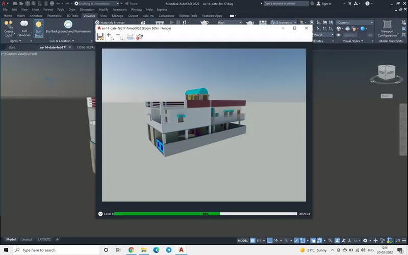
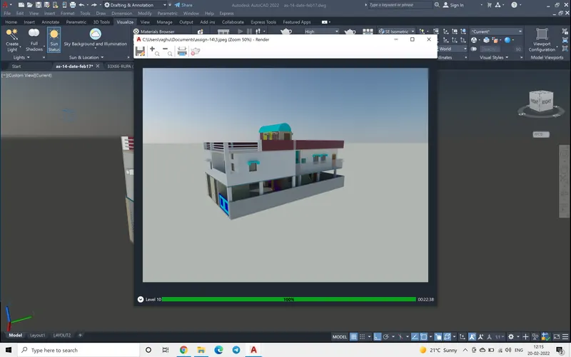
The Rendering was clicked and according to the quality chose the time taken depends.
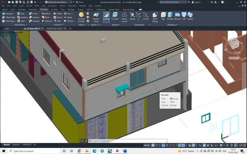
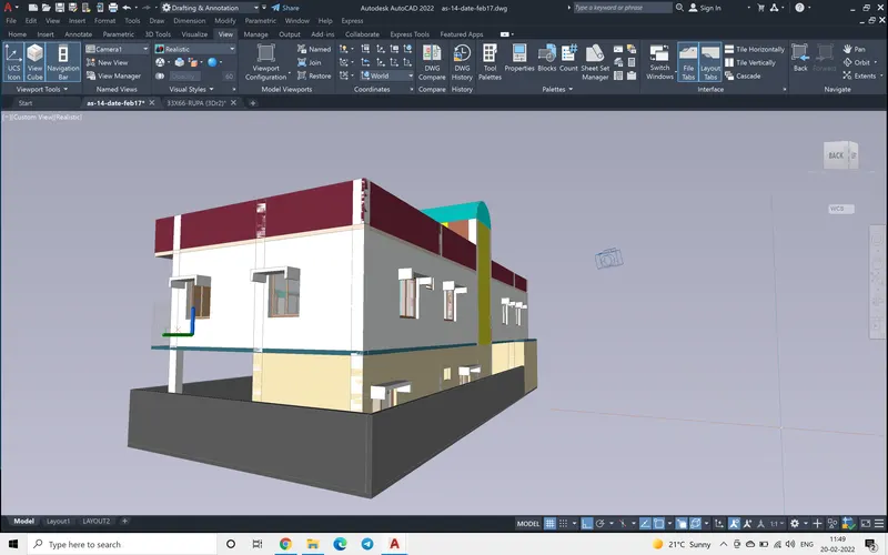
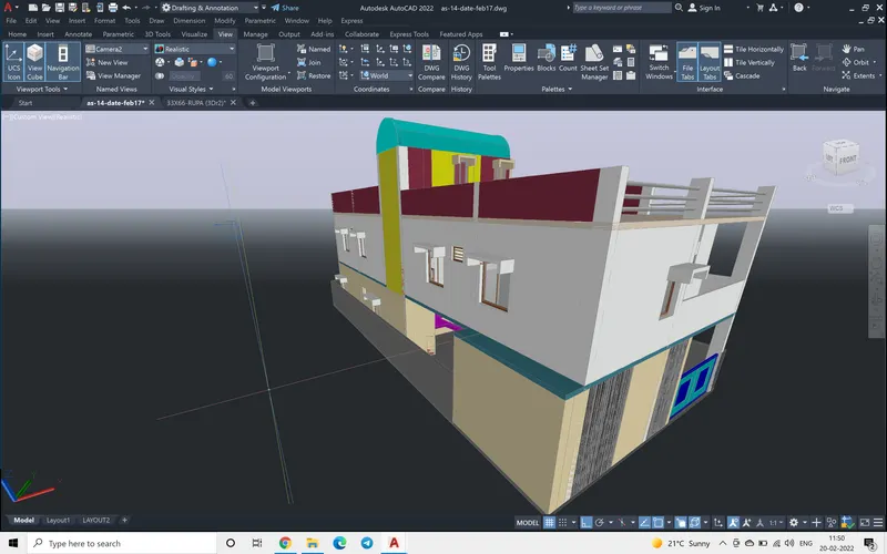
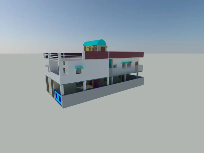
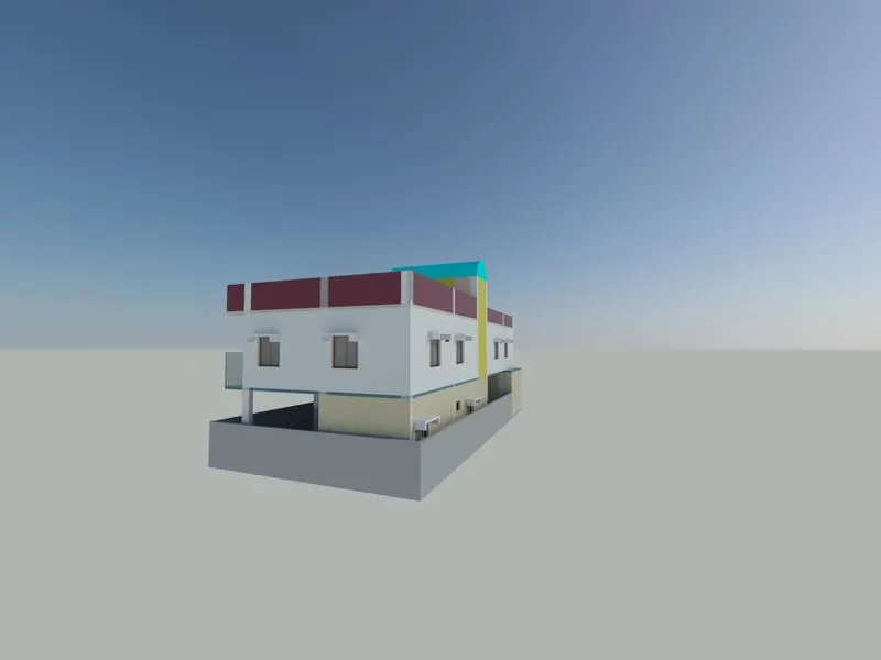
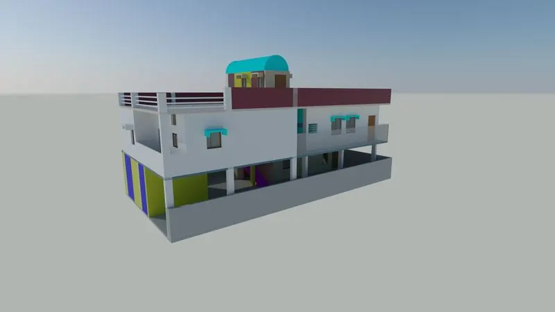
The following are the rendred images.
BY using the view ribbon and the views camera 1, cmera 2, camera3 views were chose and the rendered images were produced.