Week 1 Challenge
AIM: The aim of this challenge is to learn how the calculation of dead loads of different shape of super structure are carried. To learn the calculation of the dead load and the analysis of super structure for self weight alone using stadd.
INTRODUCTION: In the design of bridges, the whole structure is divided as substructure and super structure.
The structure including bearings, pier cap, pier and its foundation all together forms substructure.
The super stucture includes the cross girders, longitudinal girder, deck slab, kerb, walkways etc with light posts if any.
The design of bridges start with design of super structure ie, the deck slab.
The salb needs to be checked for its self weight, other immovable loads onthe slab, live loads, wind loads, earthquake loads, temperature stresses, shrinkage.
If the bridge does encounter water, then bouyant forces and water current forces needs to be considered.
The design is carried out by considereing various load combinations specified in IRC codes.
THe deck slab arrangement can be either only slab and beam arrangement, the beams here are I girder beams, this beams are either cast in situ or precast beams. The other type of system is segmental bridge.
In the current challenge, A stadd analysis for self weight of the structure has to be carried.
PROCEDURE:
Step1:
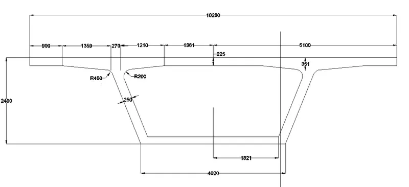
The following segment was given for dead load analysis.
THe following picture was drawn in auto cad as per the dimensions specified in the challenge.
Step 2:
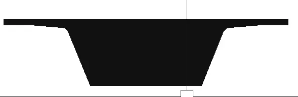
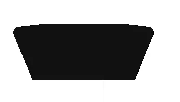
Using massproperies command the area of the segment of the outer part and then inner part are found.
The images are given below.
The massproperties command works on the areas which are either extruded i.e solid or converted to region.
Step 3: The area here is same as volume because the structure is extruded for 1000mm
i.e 13116689mm2
The Moment of inertia for the section without hole is taken first from autocad


Step 4:
The area here is same as volume because the structure is extruded for 1000mm
i.e 8578572mm2
The Moment of inertia for the inner section is taken next from autocad and deleted from the whole section shown as above.


The mass properties of the segment without any hole at the centre are taken.
The values are shown below
Area= 13116689621/1000=13116689mm2
= 13.1167m2
The following figure represents the inner box.
Area= V/1000= 8578572mm2
=8.6m2
Actual area of the segment=13.12-8.6=4.52m2
Moment of Inertia of segment X-X, Y-Y = 7788.95-3388.43=4400.52m4
Moment of Inertial of segment along Z-Z = IXX+Iyy= 4400.52+4400.52=8801.02m4
Step 5:
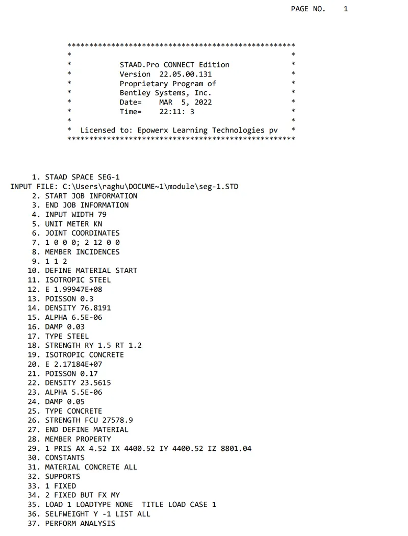
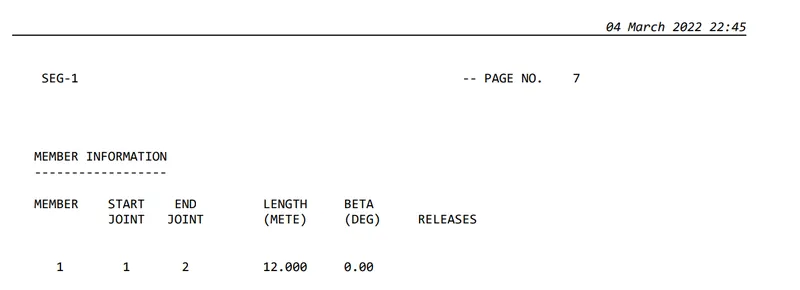
The following is the input file.
It explains the about
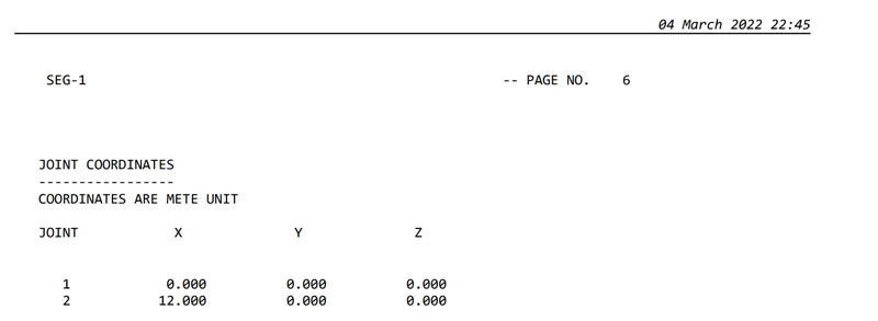
the joint coordinates, the beam member assigned between the nodes
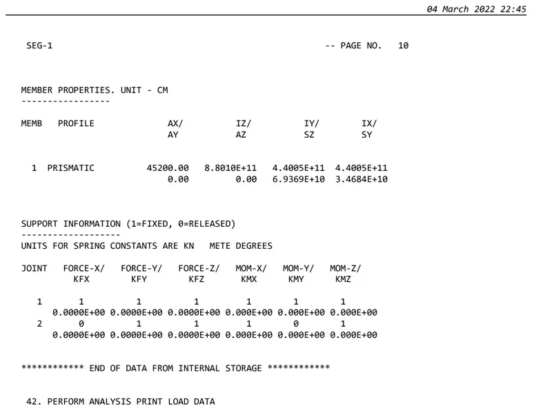
The support reactions given
at one end fixed was chose and other end FX was released and My released.
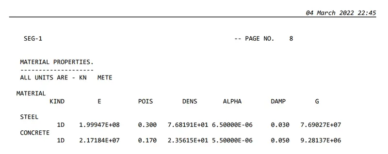
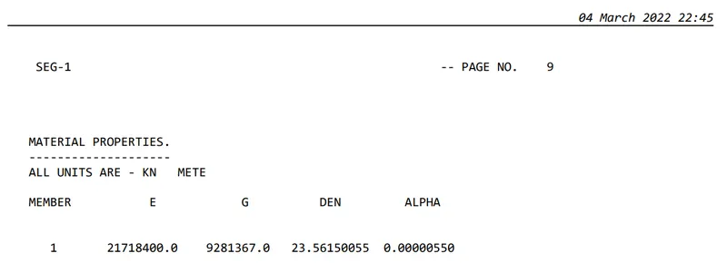
The material assigned was concrete
THe member properties were chosen as general and the properties were calculated using autocad
The Ixx = Iyy and Izz= Ixx+Iyy
The clculations are shown in the above steps.
Loading was assigned as self weeight, applied in the Minus Y direction.
Step 6:
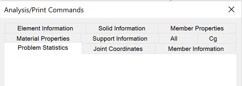
THe pre analysis icon was selected and different titles were selected.
Step 7:
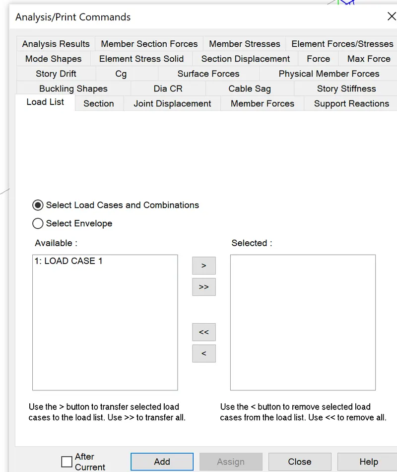
Different post analysis commands were selected along with the load case self weight
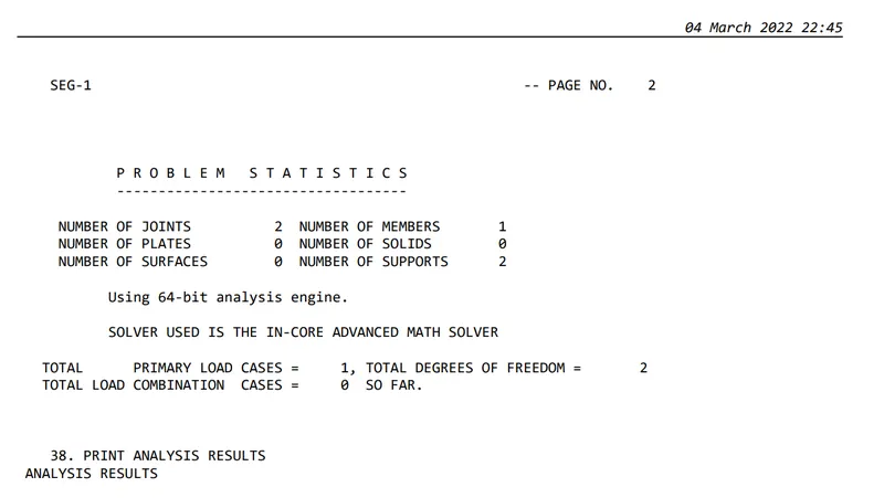
The following is the input file from the stadd analysis.
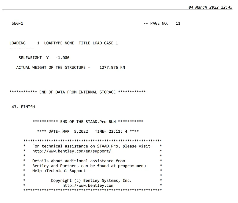
Step 8:
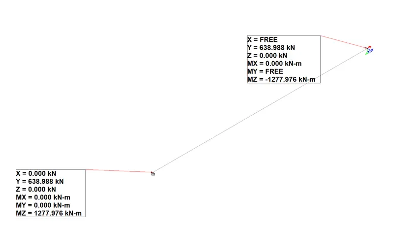
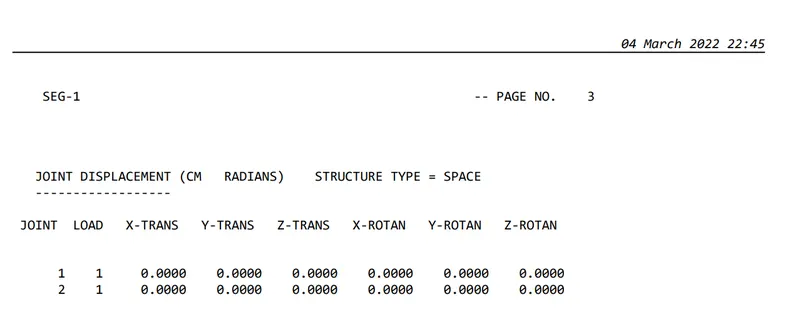
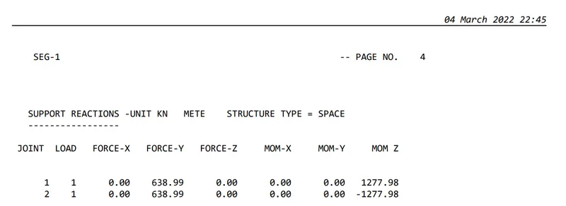
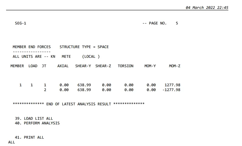
The following results were obtained after running the analysis for dead load i.e self wt alone.
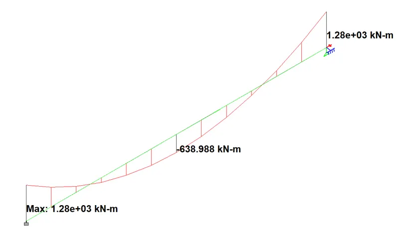
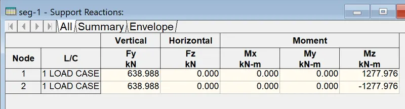
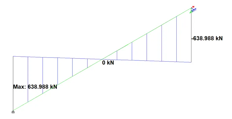
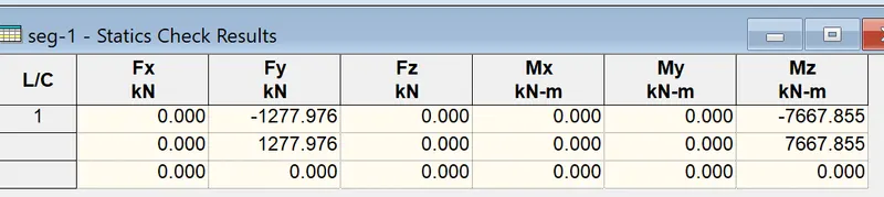
The following are the reactions, bending moments and shear force reactions on the segment.