Drafting of various geometries using Chamfer, Fillet tool in AutoCad
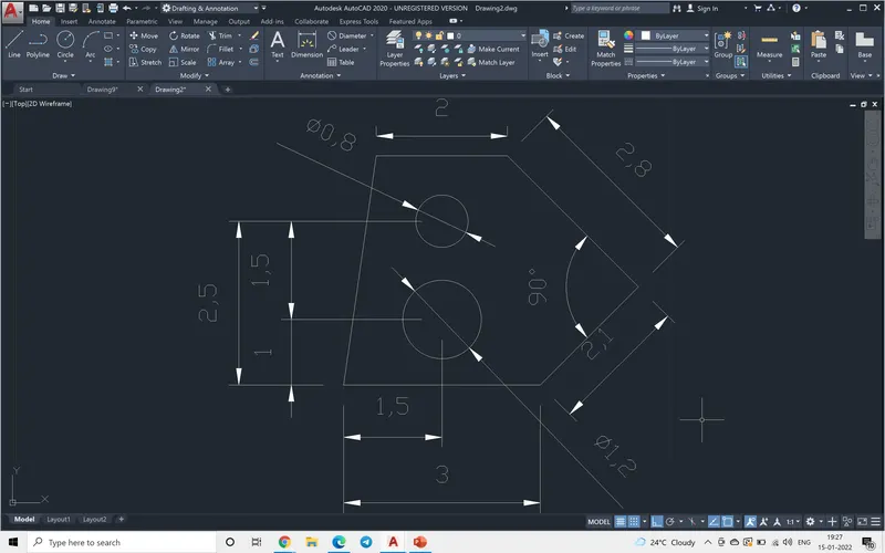
AIM: To draw the given figure with two different sized circles. The circles origin is lying on the came y plane.
INTRODUCTION: To draw the given figure, the following commands are used, PL,circle, to give the inclined measurement polar coordinate system is follwed. To annototate the dimension Dimlinear and Dimaligned are used.
PROCEDURE
Step-1
at command prompt: (polyline)PLINE is used
Specifying start point as= 5,5
Specifying next point using polar coordinates @2.12<45
Specifying next point using polar coordinates @2.83<135
Specifying next point as: 2
Specifying next point as: c
Step-2
Command: C
CIRCLE
Specifying as:6.5,6.0
Specify diameter of circle: 1.2
Step-3
Command: C
CIRCLE
Specifying center point for circle as 6.5,7.5
Specifying radius of circle as 0.4
THe drawing is done and is shown as below
*************************************************************************************************
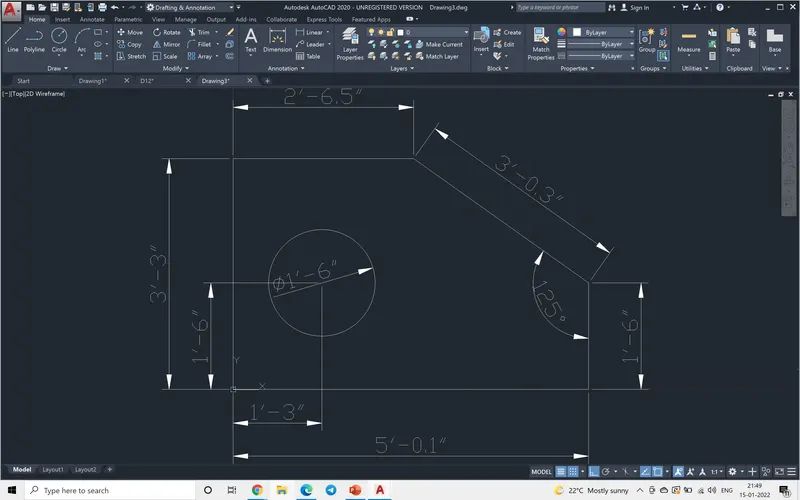
AIM: To draw the given figure with a circle. The circles centre point is given.
INTRODUCTION: To draw the given figure the following commands are used, PL,circle, to give the inclined measurement polar coordinate system is follwed. To annototate the dimension Dimlinear and Dimaligned are used.
Procedure
Step-1
Command: UN
UNITS are changed from decimal to Engineering and precision 0'.0.0".
Step-2
Command: LIMITS
Reseting the Model space limits:
Specifying lower left corner as 0',0'
Specifying upper right corner as 15',15'
Step-3
PL
PLINE
Specifying start point as 5'-0.1",1'-6"
Current line-width was 0'-0.0"
Specifying next point as 1'-6"
Specifying next point as 5'-0.1"
Specifying next point as 3'-3"
Specifying next point as 2'-6.5"
Specifying next point as c
Step-4
Command: C
CIRCLE
Specifying center point for circle as 1'-3",1'-6"
Specify diameter of circle: 1'-6"
Step-5
Command: _dimlinear
Specifying first extension and second extension line origin:
Specifying dimension line as
Dimension text = 2'-6.5"
Step-6
Command: DIMLINEAR
Specifying first extension and second extension line origin:
Specifying dimension line as
Dimension text = 3'-3"
Command: DIMLINEAR
Specifying first extension and second extension line origin:
Specifying dimension line as
Dimension text = 5'-0.1"
Command: DIMLINEAR
Specifying first extension and second extension line origin:
Specifying dimension line as
Dimension text = 1'-6"
Command: _dimaligned
Specifying first extension and second extension line origin:
Specifying dimension line as
Dimension text = 3'-0.3"
Step-7
Command: _dimdiameter
Selecting circle and
Dimension text = 1'-6"
Command: _dimdiameter
Select arc or circle: *Cancel*
Command: _dimlinear
Specifying first extension and second extension line origin:
Specifying dimension line as
Dimension text = 1'-3"
Command: DIMLINEAR
Specifying first extension and second extension line origin:
Specifying dimension line as
Dimension text = 1'-6"
THe drawing is done and is shown as below
*******************************************************************************************
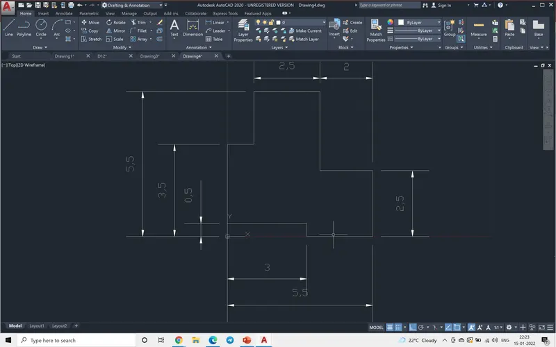
AIM: To draw the given figure with a circle.
INTRODUCTION: To draw the given figure the following commands are used, PL. The cursor was just moved in the required direction with orth on and required dimension was specified.
PROCEDURE
Step-1
Command: PL
PLINE
Specifying start point: 5.5,2.5
Current line-width is 0.00
Specifying next point as 2.5
Specifying next point as 0.5
Specifying next point as 3
Specifying next point as: 3
Specifying next point as 1
Specifying next point as 2
Specifying next point as 2.5
Specifying next point as 3
Specifying next point as C
Step-2
Command: _dimlinear
Specifying first extension and second extension line origin:
Specifying dimension line as
Dimension text = 2.5
Command: _dimlinear
Specifying first extension and second extension line origin:
Specifying dimension line as
Dimension text = 2.5
Command: DIMLINEAR
Specifying first extension and second extension line origin:
Specifying dimension line as
Dimension text = 2
Command: DIMLINEAR
Specifying first extension and second extension line origin:
Specifying dimension line as
Dimension text = 2.5
Command: DIMLINEAR
Specifying first extension and second extension line origin:
Specifying dimension line as
Dimension text = 5.5
Command: DIMLINEAR
Specifying first extension and second extension line origin:
Specifying dimension line as
Dimension text = 3
Command: DIMLINEAR
Specifying first extension and second extension line origin:
Specifying dimension line as
Dimension text = 0.5
Command: DIMLINEAR
Specifying first extension and second extension line origin:
Specifying dimension line as
Dimension text = 3.5
Command: DIMLINEAR
Specifying first extension and second extension line origin:
Specifying dimension line as
Dimension text = 5.5
THe drawing is done and is shown as below
*************************************************************************************
AIM: To draw the given figure with 3 circles.
INTRODUCTION: To draw the given figure the following commands are used, PL, circle and mirror commands.
Procedure: Polyline command was used to draw the outer box and circle command for drawing centre circle and the one side of the box here left circle was drawn and it was mirrored to the right side of the box.
Step-1
Command: un , units command is used to set the units of the drawing.
Step-2
Command: PL
PLINE
Specifying start point as 11.5,6
Current line-width is 0.00
Specifying next point as 6
Specifying next point as 11.5
Specifying next point as 6
Specifying next point as c
Step-3
Command: LIMITS
Reset Model space limits:
Specifying lower left corner as <0.00,0.00>:
Specifying upper right corner as: 15,15
Step-4
Command: C
CIRCLE
Specifying center point for circle as 1.5,3
Specifying diameter of circle as 1
Command: C
CIRCLE
Specifying center point for circle as 1.5,3
Specify diameter of circle as: 2
Command: C
CIRCLE
Specifying center point for circle as 5.75,3
Specify diameter of circle as: 3
Step-5
Command: MI
MIRROR
Selecting objects 2 circles
Specifying first point of mirror line and Specifying second point of mirror line:
Erase source objects? [Yes/No] : n
THe drawing is done and is shown as below
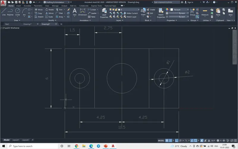
********************************************************************************
AIM: To draw the given figure .
INTRODUCTION: To draw the given figure the following commands are used, PL , fillet and circle.
Procedure: The outer rectagle was drawn first then the circles were created, using the fillet command with radius the corners with given the required curves.
Step-1
Command: LIMITS
Reseting Model space limits:
Specify lower left corner <0.00,0.00>:
Specify upper right corner : 250,150
Step-2
Command: PL
PLINE
Specifying start point as 11.5,6
Current line-width is 0.00
Specifying next point as 210
Specifying next point as 75
Step-3
Command : C ,drawing circle
Specifying the centre point of circle and giving the radius as 190,25 and radius 15.
Specifying the centre point of another circle and giving the radius as 190,25 and radius 25.
Step-4
Command: PL
PLINE
Specifying start point at the quadrant of circle radius 25, Moving parallel to Y axis at a point in line with quadrant of circle radius 15.
Speciying the horizontal dimension, pick any point beyond the left circle.
Drawing the left circle at he botton.
Step-5
Command : C
circle
Specifying the centre point of circle as 35,0 and giving the radius as 25.
Specifying the centre point of circle and giving the radius as 35,0 and radius 35.
Step-6
Command: F
FILLET
Current settings: Mode = TRIM, Radius = 6.00
Select first object or [Undo/Polyline/Radius/Trim/Multiple]: r
Specify fillet radius <6.00>: 20
Step-7
FILLET
Current settings: Mode = TRIM, Radius =20
Selecting first object or [Undo/Polyline/Radius/Trim/Multiple]: r
Specifying fillet radius <6.00>: 20
THis radius is used thrice in the drawing.
Step-8
Drawing the rectangles in the drawing.
PLINE (for drawing rectangle)
Specify start point: 20,60
Specifying next point : 30
Specifying next point : 70
Specifying next point : 30
Specifying next point : c
THe drawing is done and is shown as below
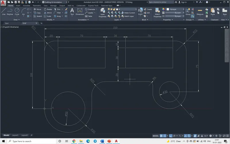
***************************************************************************************************
AIM: To draw the given figure .
INTRODUCTION: To draw the given figure the following commands are used, PL , fillet and circle.
Procedure: THe centre circles were drawn first and the left side circles were drawn. the left side circles were mirrored to the right side. using line command the lines are drawn connecting the circles with left to the centre. Those lines were mirrored again to the right side and unwanted lines were trimmed.
Step-1
Command: un
UNITS
Command: LIMITS
Reseting Model space limits:
Specifying lower left corner : 0,0
Specify upper right corner : 10,10
Step-2
Command: C
Circle
Specifying center point for circle: 5,5
Specify radius of circle or [Diameter]: d
Specify diameter of circle: 5
Command: C
CIRCLE
Specify center point for circle as 5,5
Specify radius of circle or [Diameter] : d
Specify diameter of circle : 4
Step-3
Command: CAL
>> Expression: 5-4.275
0.725
Step-4
Command: C
CIRCLE
Specify center point for circle or [3P/2P/Ttr (tan tan radius)]: 0.725,5
Specify radius of circle: 0.9
C
CIRCLE
Specify center point for circle or [3P/2P/Ttr (tan tan radius)]:
Specify dia of circle :1.8
Step-5
Command: MI
MIRROR
Selecting objects: 2 found
Selecting objects: Specifying first point of mirror line:Specifying second point of mirror line:
Erase source objects? [Yes/No]: no
Step-6
Command: PL
PLINE
Specifying start point:
Current line-width is 0.00
osnap selecting tangent,drawing tangent lines on the left side of the centre circle both up and down.
Specifying next point
Step-7
Command: MI
MIRROR
Selecting objects: 2 total
Specifying first point of mirror line:Specifying second point of mirror line:
Erase source objects? [Yes/No] : no
Step-8
Command: TR
Trimming the circles.
Select cutting edges ...
THe drawing is done and is shown as below
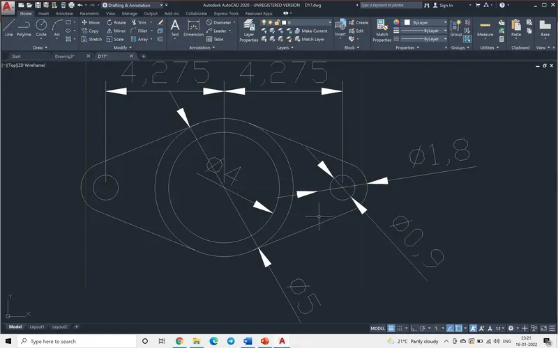
**********************************************************************************************
AIM: To draw the given figure .
INTRODUCTION: To draw the given figure the following commands are used, fillet and circle.
Procedure: two circles of different diametres are drawn and kept at specified distance apart. The fillet command is used to draw the lower curve. The upper curve is drawn using the centre of the intersecting circles which are drawn at the centres of the small circles.The calculation of the radius is given below.
Step:1
Command: LIMITS
Reset Model space limits:
Specifying lower left corner as: 0,0
Specify upper right corner : 50',20'
Step 2:
Command : C
Drawing circles by picking centre point at 8',8'
giving radius 8'
Step 3:
Command - circle
drawing another circle by picking center at 40'-8",8"
giving radius as 9"
Step-4
Now we have to draw two more circles one at centre 8,8 with radius 41'-8"-8'=33'-8"
another circle with centre at 40'-8",8', with radius 41'-8"-9'=32'-8"
Step-5
The above two circles intersect at two points, now picking the lower intersecting point as centre for new circle, this circle will meet the two small circles at top. Using fillet command drawing radius of 41'-8"
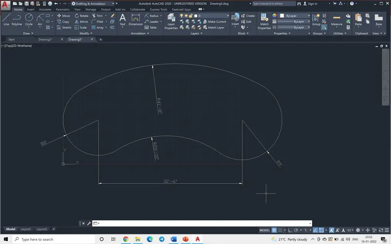
*****************************************************************************************
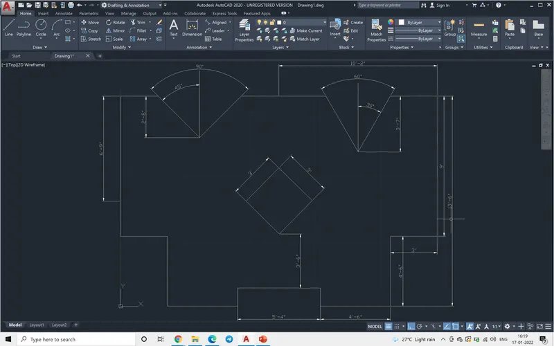
AIM: To draw the given figure .
INTRODUCTION: To draw the given figure the following commands are used, rectangle.
Procedure: The outer rectangle is drawn first and then the inner square which is rotated to 45 degrees and V notches are drawn.
Steps-1
Command Limits
speciying lower left corner:0,0
Upper corner as : 21,14
Steps-2
Command: UN
UNITS
Command: GRID
Specifying grid spacing: l
Display grid beyond Limits [Yes/No] : n
Steps-3
PLINE (for drawing rectangle)
Specify start point: 0,4'-6"
Specifying next point : 9'
Specifying next point : 20'-4"
Specifying next point : 9'
Specifying next point : 3'
Specifying next point : 4'-6"
Specifying next point : 4'-6"
Specifying next point : 1'-2"
Specifying next point : 2'-8"
Steps-4
Command: MI
MIRROR
Select objects: 5 found
Select objects: Specify first point of mirror line:
Specify second point of mirror line:
Erase source objects? [Yes/No] : no
Steps-5
Command: Rectangle
SPecifying starting lower left corner and upper right corner as 3',3'.
Rotating the rectangle by 45degrees, and placing it at 10'-2",6'-5''
Steps-6
Command: Line
picking the start point of the line as 5'-1",10'-10" and giving dimension as 2'-8"
Rotating the above line about 45 degrees.
Command mirror is used to draw a similar line making a v notch in the drawing
Steps-7
Command: TR
TRIM
trimmimg the lines to form the v notch.
The following figure is drawn.
********************************************************************************************
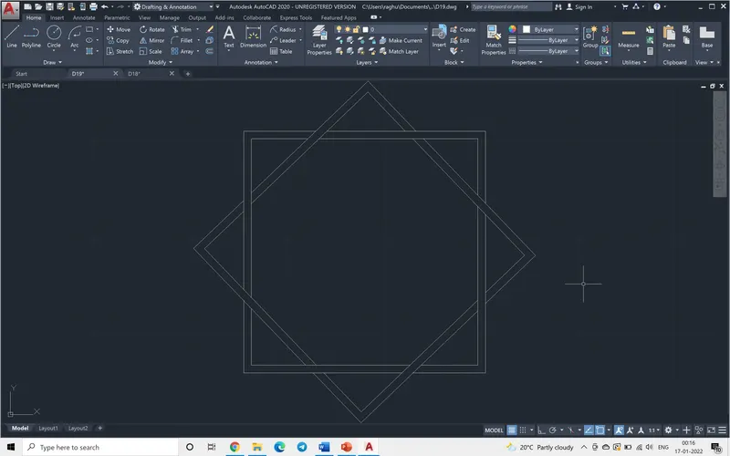
AIM: To draw the given figure .
INTRODUCTION: To draw the given figure the following commands are used,polyline, rotate, mirror rectangle.
Procedure: To draw the square and then mirroring it to the required angle. after the required shape is obtained then by using offset command parallel lines are drawn all around the required shape. Using the trim command the unwanted lines are removed.
Steps-1
Command Limits
speciying lower left corner:0,0
Upper corner as : 10,10
Steps-2
Command: UN
UNITS
Command: GRID
Specifying grid spacing: l
Display grid beyond Limits [Yes/No] : no
Steps-3
Command: REC
RECTANG
Specifying first corner point picking some point ont he sheet.
Specify other corner point : @125,125 ( a square is drawn)
Steps-4
Command: MI
MIRROR
Select objects: 1 found
Select objects: Specify first point of mirror line:
Specify second point of mirror line:
Erase source objects? [Yes/No] :
Steps-5
Command: O
OFFSET
Specifying offset distance : 4
by choosing the above drawn square to offset through a distance of 4.
Steps-6
Command: TR
TRIM
trimmimg all the unwanted crossing lines, to aarive at the following figure.
**************************************************************************************************************
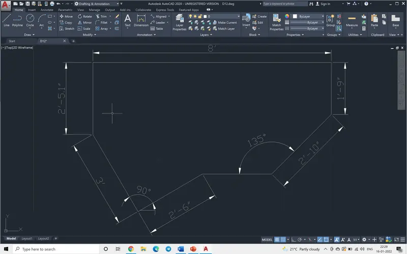
AIM: To draw the given figure using polyline.
INTRODUCTION: To draw the given figure, the following commands are used,(polyline) PL, to give the inclined measurement polar coordinate system is follwed. To annototate the dimension Dimlinear and Dimaligned are used.
PROCEDURE
Step-1
at command prompt: (polyline)PLINE is used
Specifying start point as picking some point on sheet
Specifying next point as 2'-5.1"
Specifying next point as 8'
Specifying next point as 1'-9"
Specifying next point using polar coordinates @2'-10"<225
Specifying next point using polar coordinates @x<135
Step-2
At command prompt again using a pline drawing an "l" figure which measured 3' in standing leg and 2'-6" in horizontal length. The "L" was moved to the starting point and the rotated to bring the given shape.