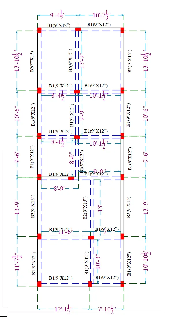
Project 1 _Creating an Architectural plan for the provided plot size and develop relevant basic structural drawings
AIM : The aim of this project is to draw an Architectural plan on 60x20 plot size.
The aim also includes, to draw the floor plan, ( here i have considered a duplex house) then elevations of the house at different section, stuctural drawing which include the column and footing layout, plinth beam layout and the reinforcement details of both footing, plinth beam and column.
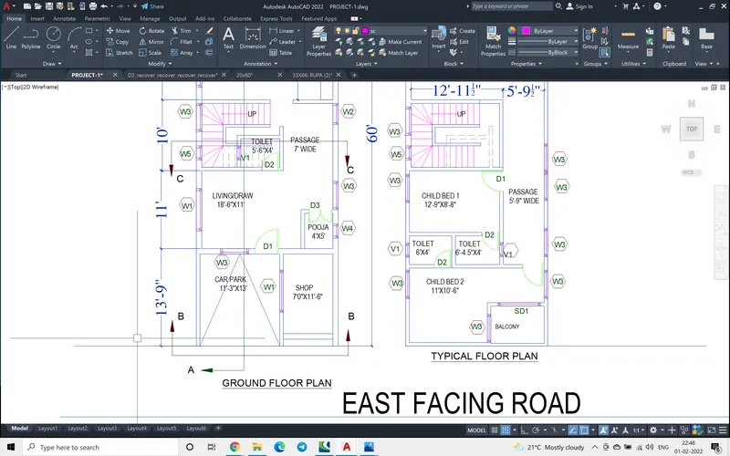
INTRODUCTION: The architectural plan was drawn (considering a duplex house). Two sections were taken through the stair case, there is a toilet which has sunken slab. To high light the stair cas details and the sunken slab the section was shown away from the first step towards the toilet. A window, door and ventilator schedule is also shown.
The ground level and the ground floor is having a 1.5' difference, a three step of 6" is given to approch this level. P.C.C of 2" thk and 3" concrete under the P.C.C is shown and the remaining depth earth fill and below that brickbat or gravel fill of 3.5" thick is shown.
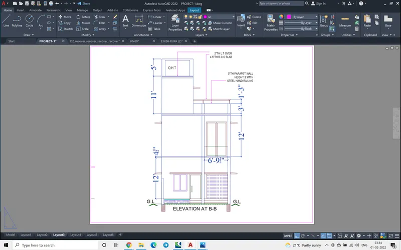
The balcony door shown in the elevation is glazed door. Each floor height is taken as 12' and the head room height is taken as 10'. For over head tank the height is taken as 5' x7'. The tread is considered as 10" and rise as 6" for stair case, at stair landing level the winder landings (kite landings) are used.
There is a small commercial space provided in the north east corner of the plot, the plot is east facing. There is a living, puja, kitchen/dinning, stair case, store, two toilet/Bath and bedroom in the ground floor. In the first floor there are three bed room, one masterbed, two child bedrooms,3 toilet/bath, 2 balconies and a drawing/living area.
A parapet wall of 3' height with railing trough out is provided.
PROCEDURE:
Step -1.
Using layer command, the following different layers were used, with different colour and different line weights and line thickness, and the condition whether the layer to be seen while plotting is also checked for some of the layers.
Here the layers which were used in the drawing were separated using filterlayer command. The filter option taken was 'off', the layers which I have used are put off and grouped to a filter name layerused. There were few layers which were not active, inorder to not to show them in the picture i have used filterlayer command.
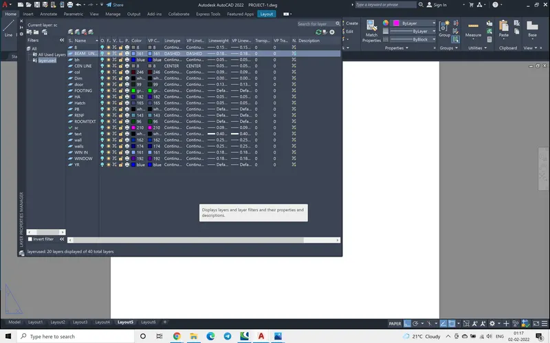
Step 2:
Using XLine command the construction lines were dawn along the boundary 20x60 of the site. then the external wal thickness is considered as 9" and the internal wall thickness as 6" was considered, different room dimensions are provided.
Step 3:
Using offset, fillet and trim command all the rooms were drawn.
Step 4:
Using arc and the poly line command doors were drawn and located at the different locations. Same as the windowa and ventilators were drawn
Step 5:
The command Mtext was used to write the room names and dimension provided were typed.
Step 6:
Using D dimension style command the dimension style was set and whole plan and different room dimensions were annotated.
QL command was used to show the pointer and mtext was used to annotate the write up.
And to draw the section A-A, B-B, C-C QL was used.
The following plan was achieved.
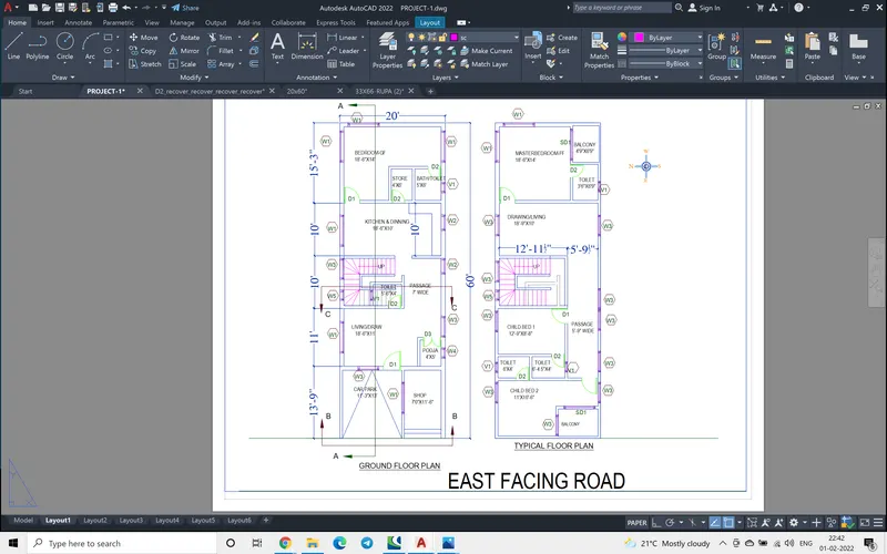
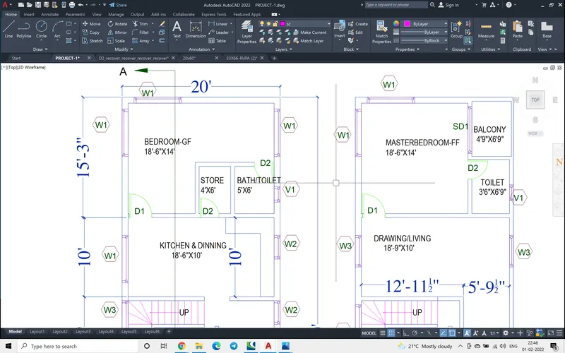
Step 7:
The command XL was used to project the plan and the elevation was drawn using, trim. offset commands.
Step 8:
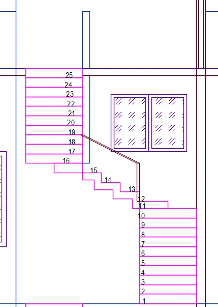
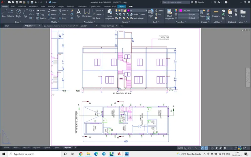
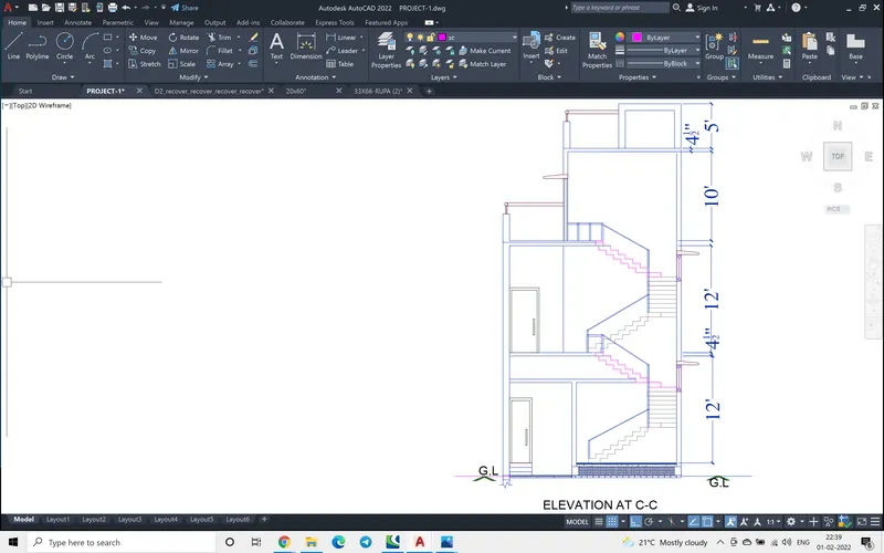
Using poly line command the stair case was drawn, the railings, winding stairs were shown both in section A-A, C-C.
THE INITIAL FLIGHT HAD 8 STEP STRAIGHT 10"X6"
The winder or kite steps wer 4 nos of same 6" height and the 3 staright steps again 4 winder steps and then the second flight of 7 steps to reach the floor.
Step 9:
The offset command was used to locate the floor heights of 12' and head room ht of 10' and slab thickness 4.5".
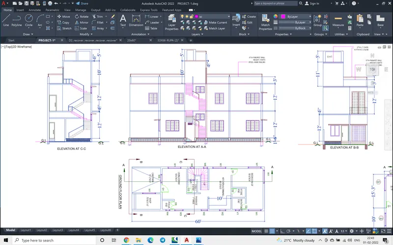
The following drawings are achieved. The door height was taken as 7', the doors were drawn using polyline command. The door handles were drawn using rectangle command.
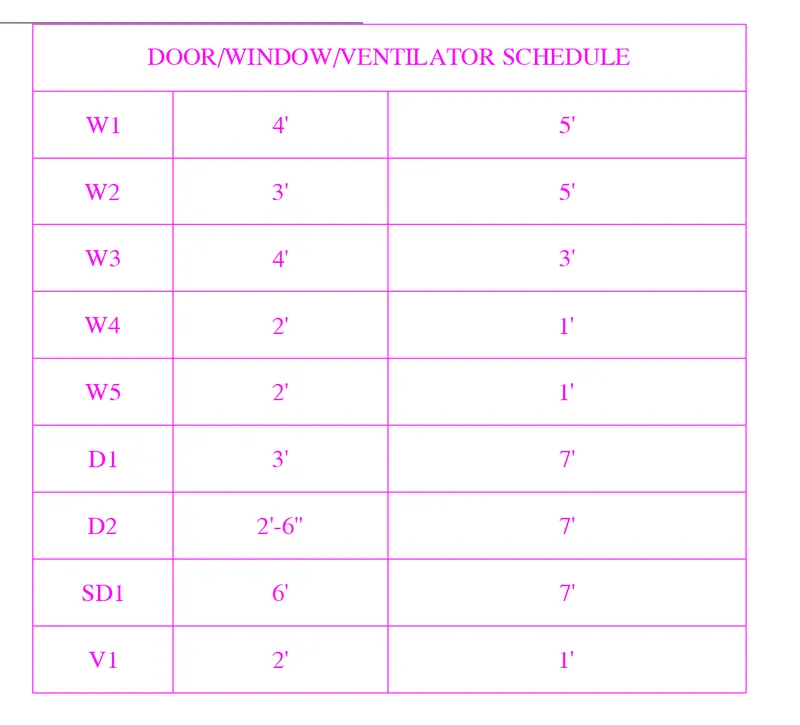
THE FOLLOWING SCHEDULE OF DIMENSIONS FOR DOOR, WINDOWS AND VENTILATOR WERE USED.
Step 10:
The secton A-A shows the staircse along the sunken toilet details, also the winding stair details.
Step 11:
The commands offset, Xline, trim, copy, hatch, dimstyle etc were used to achieve the following elevation at C-C. The stairs details in the other direction are detailed.
Step 12:
The following front elevation is achieved by projecting the front plan of the architectural drawing using Xline, then offset, trim, copy, hatch, dimensionline, mtext etc.
Step 13:
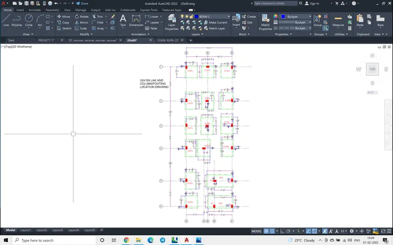
The following structural drawings are achieved,
Keeping all other layers lock and the require centerline, column, footing, text layers on the following drawings are drawn. This helps to work fast as the reference layers will not gets disturbed.
Here at thwo grid locations the footings are overlapping therefore combined footing are given.
THe outer column are of one type and the inner column are of one type, C1, C2 are used.
Footings are of F1 to F4 and CF1 and CF2 are used.
Usind Dimlinear the annotations were criied out.
The command polyline was used and offset command was used.
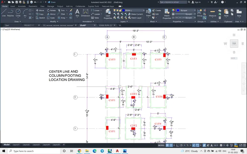
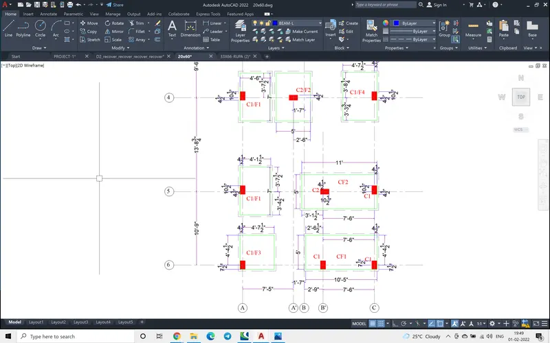
Step 14:
The column and the footing details are provided using command table, mtext.
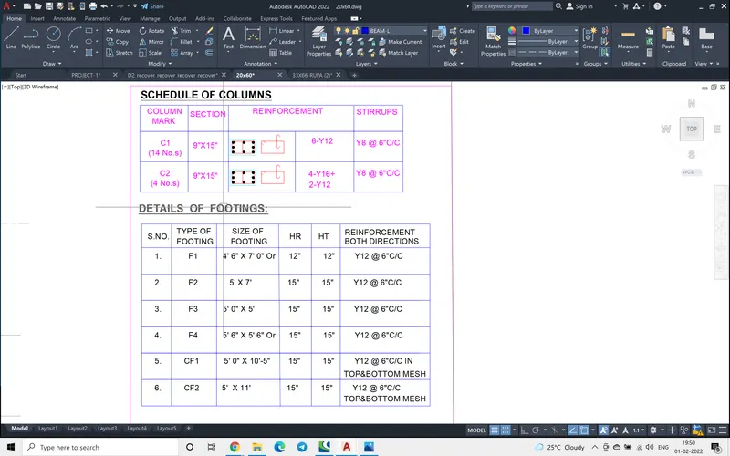
Step 15: A typical plan and elevation of footing/column drawings is shown.
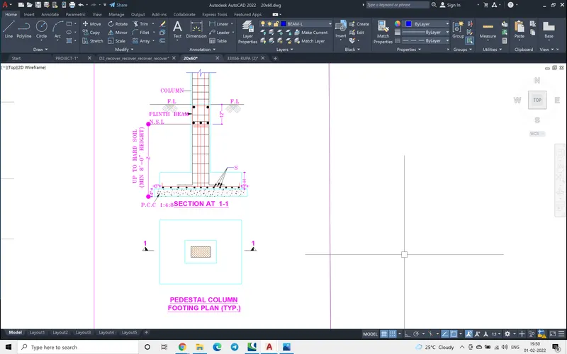
Step 16:
Keeping the column layer alone active and all other layers frozen and the beam line layer on the following drawing is achieved. Using text layer as current the different plinth beam drawings were annotaed,
also the renforcement details are provided for plinth beams.
The following drawings are achieved.
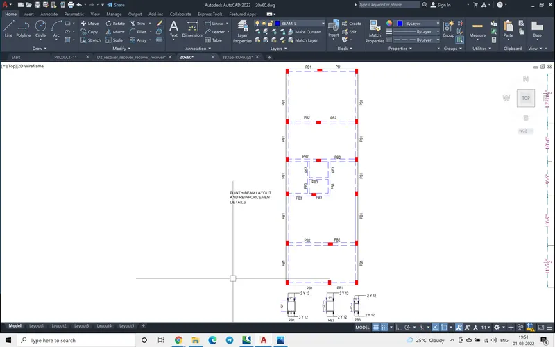
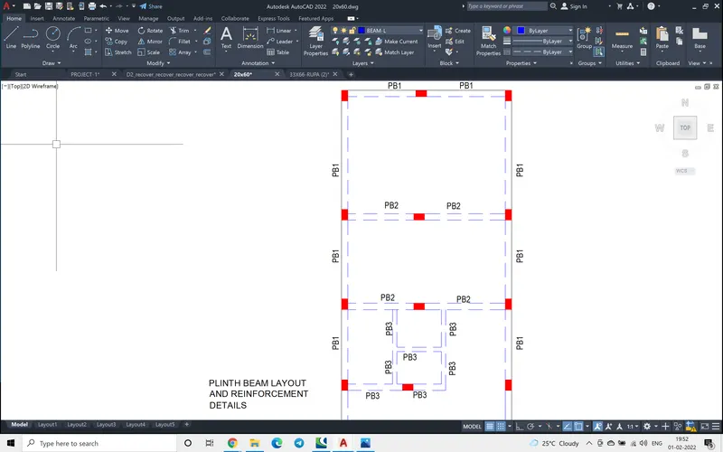
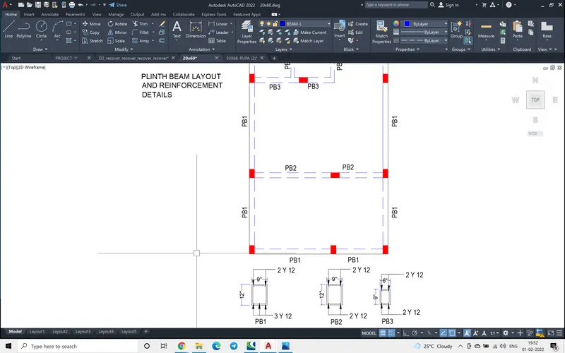
The following is the general way of representing the beam layout at the slab level, the beam sectional elevations showing the reinforcement details needs to be developed after properly designing them.