Week 5 Challenge
AIM:The aim of this challenge is apply the wind loads on the superstructure and analyse the structure using stadd.
IS 875 part 3 gives about the wind loads and IRC 6 also mentions about the wind loads to be considered on the super structure while analysing the structure.
INtroduction:
The dimensions of the bridge are as follows
The span of the bridge is 15mc/c
the deck width = 5mc/c
The dimensions of the rectangular girder are 2m depth 0.5m width
The dimension of the cross girder are 1.4x0.5
Given are the dimensions of the pier, 1.5x1.5
The foundation depth is taken as 2m depth.
THe foundation is considered as a plate element and the spring support were given with modulus of subgrade reaction as 120000 kN/m^2/m
The junction between the foundation and the pier was given a fixed support.
The deck slab was defined as plate element of thickness 0.3m
******************************************************************************
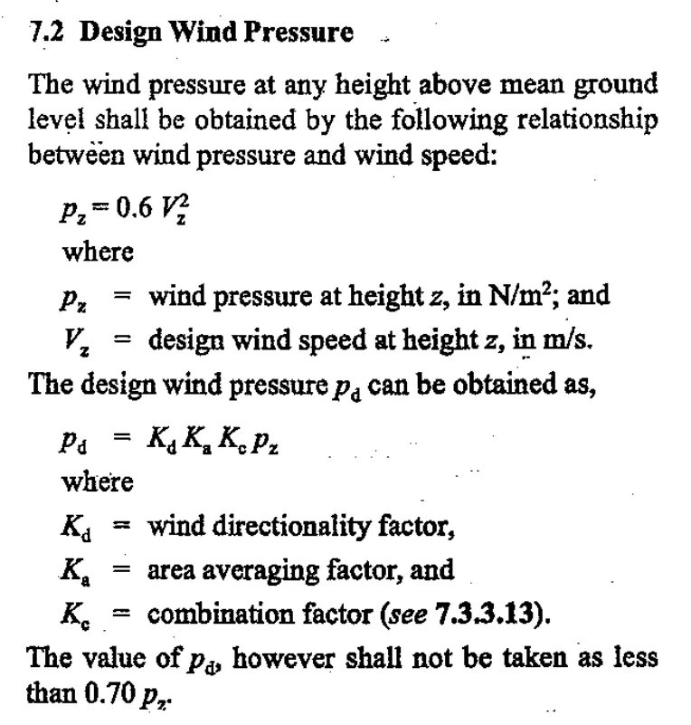
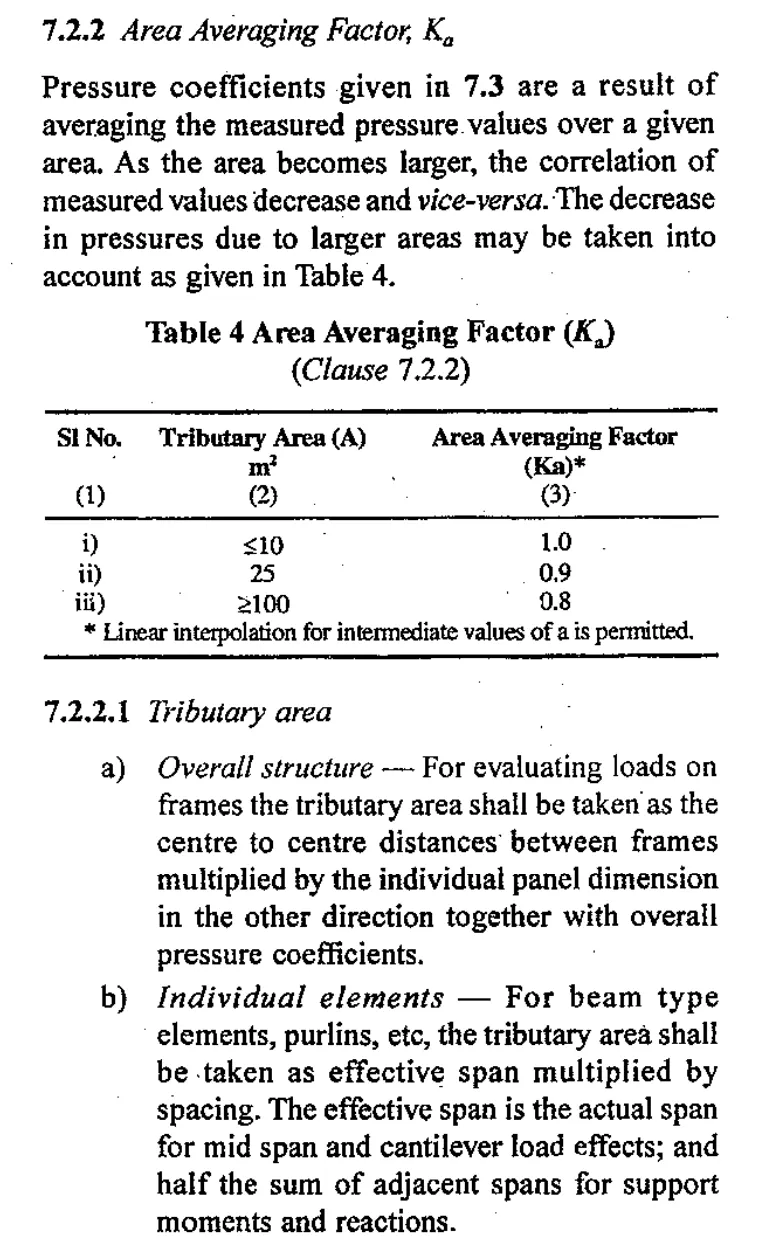
The Following are the wind pressure calculations as per IS 875 part - 3.
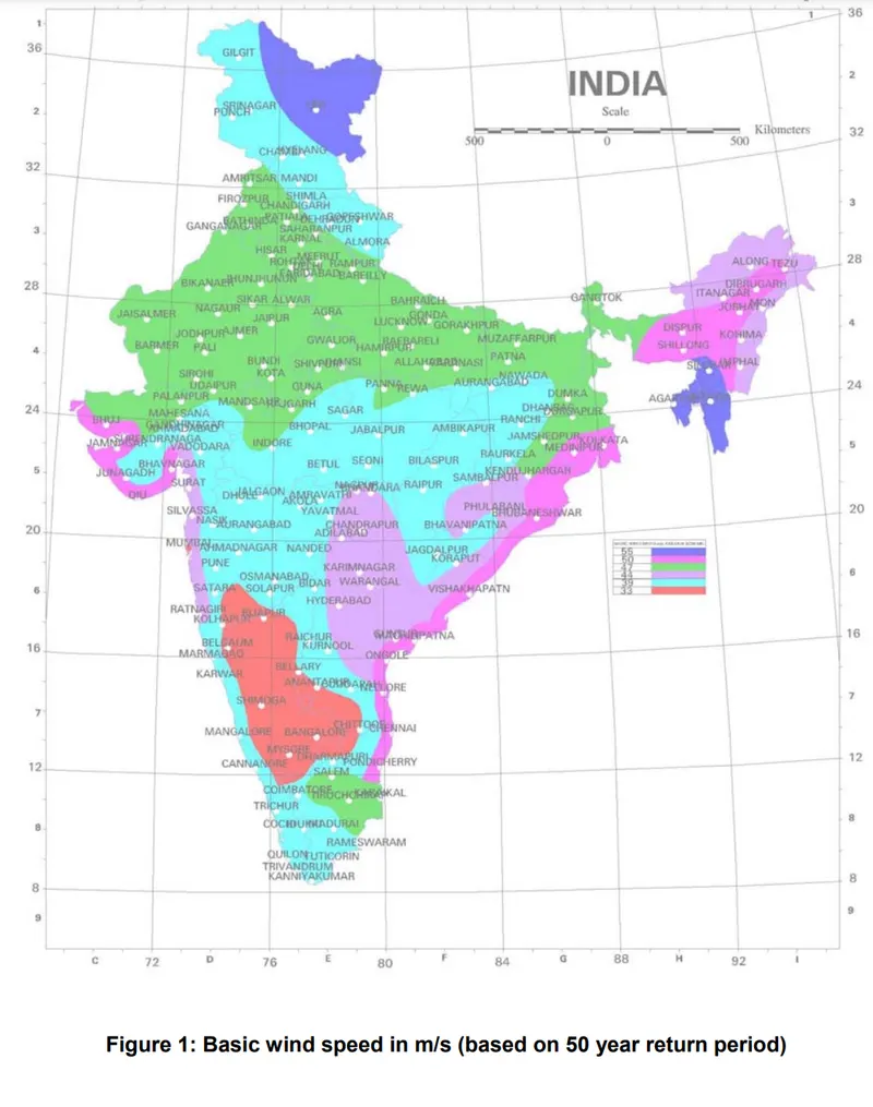
From the challenge the bridge is located in MUmbai
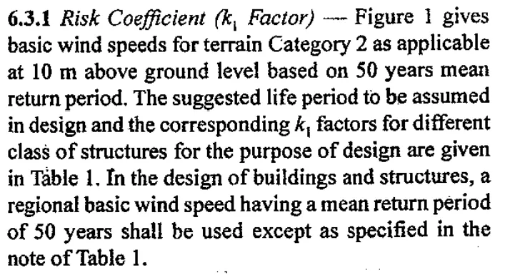
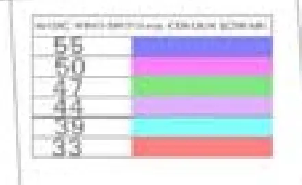
According to IS875 part 3 and IRC 6 the Vb - basic wind speed is 44m/s
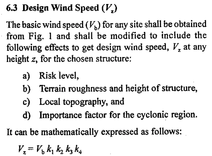
Vz= VbxK1xK2xK3xK4
Vb=44m/s
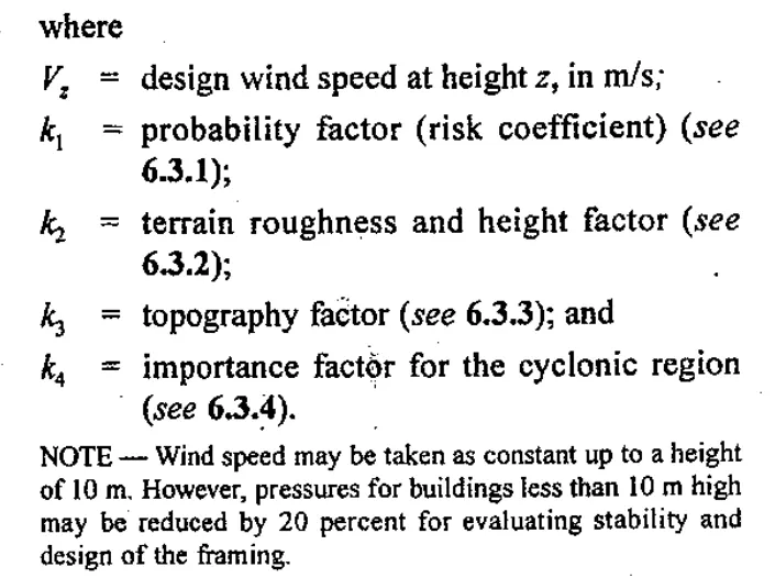
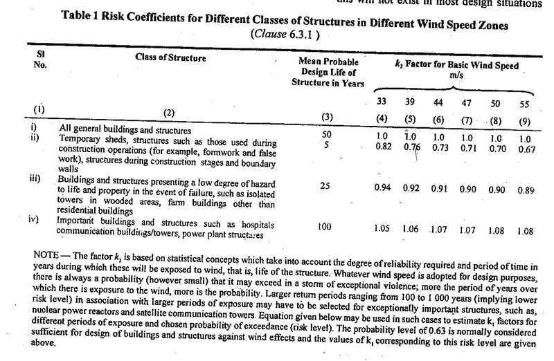
Since the bridge height is less than 10m, k1 is taken as 1.0
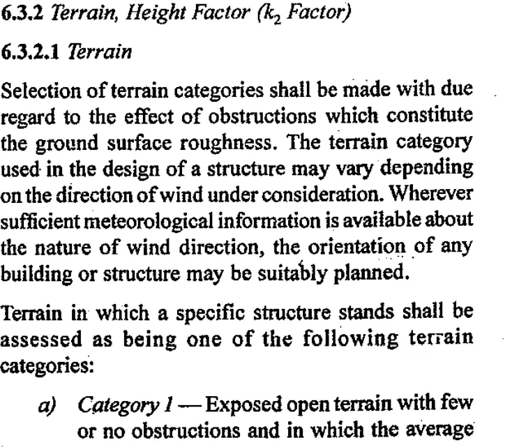
K2- for terrain category -2 (according to the description fron the question)-1.0
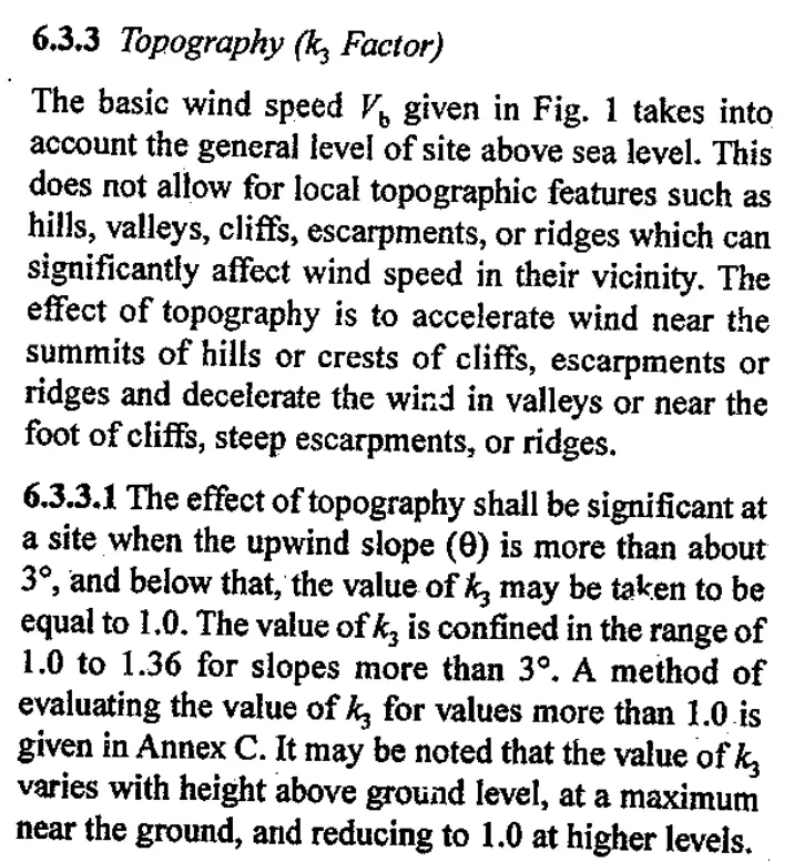
K3- is also 1.0
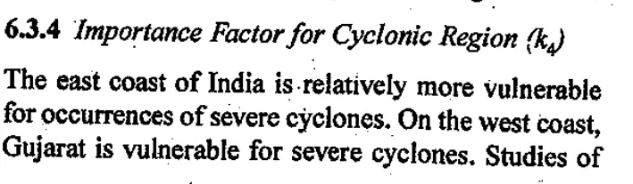
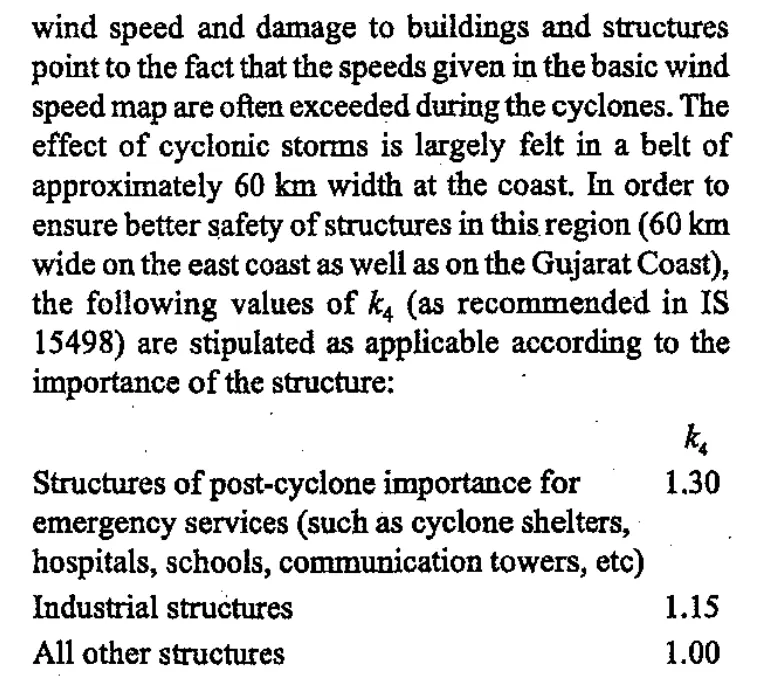
K4- Importance factor for cyclone region. 1.30 (Mumbai)
Vz = 44x1x1x1x1.3=57.2m/s
Design wind pressure =
Pd=KdxKaxKcxPz=1x1x1x1963.104
Pz=0.6xVz^2 (the pressure at any height z)
= 0.6x57.2x57.2=1963.104N/m^2
= 1.963kN/m^2
This pressure is applied on the pier of dimension 1.5x1.5 as udl
The calculations are as following
The design wind pressure 1.963kN/m^2
The above pressure multiplied by 1.5
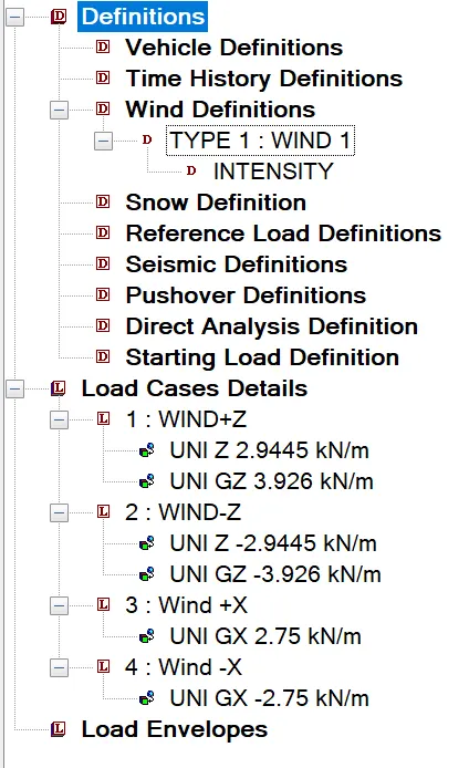
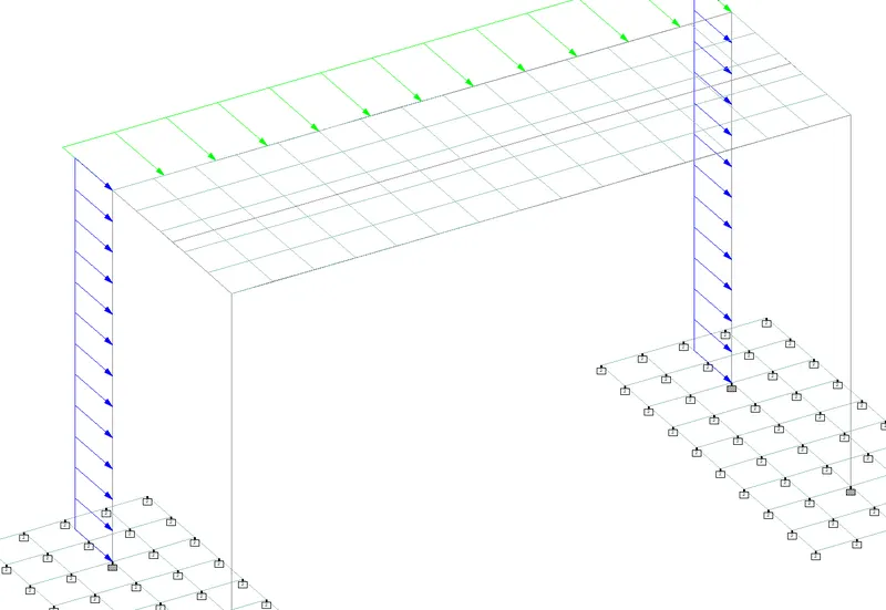
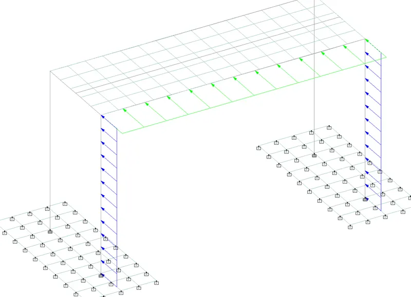
1.963x1.5=2.9445kN/m ( on the piers)
On the super structure
The depth of main girder is 2.0 m
1.963x2=3.926kN/m
The depth of cross girder = 1.4m
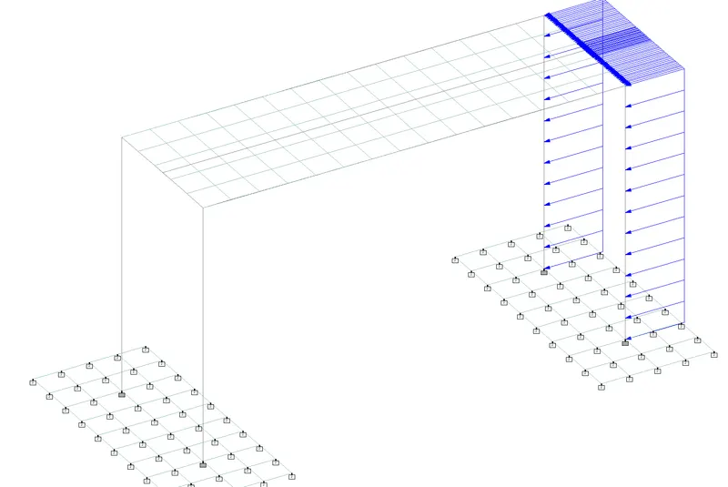
1.963x1.4=2.75kN/m
******************************************************************************
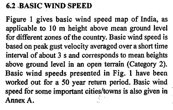
The following are the Clause from the IS 875 part-3 used in the design of the bridge for the wind loads
The following are the clause given in the IS code 875 part 3.
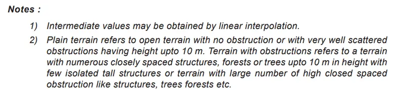
The K1 value is given only for the structures whose height is 10m or more than that. For structures less than 10 the wind speed is taken constant.

******************************************************************************************
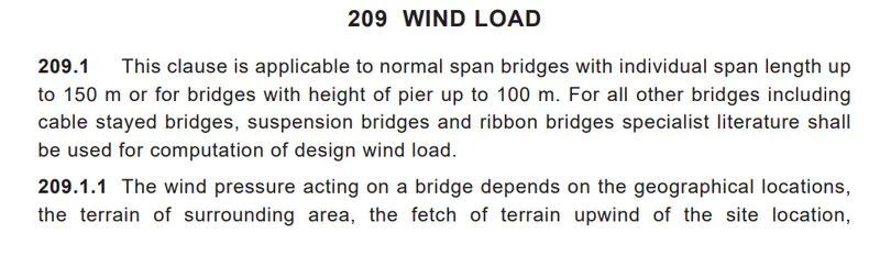
Wind Load as per IRC - 6
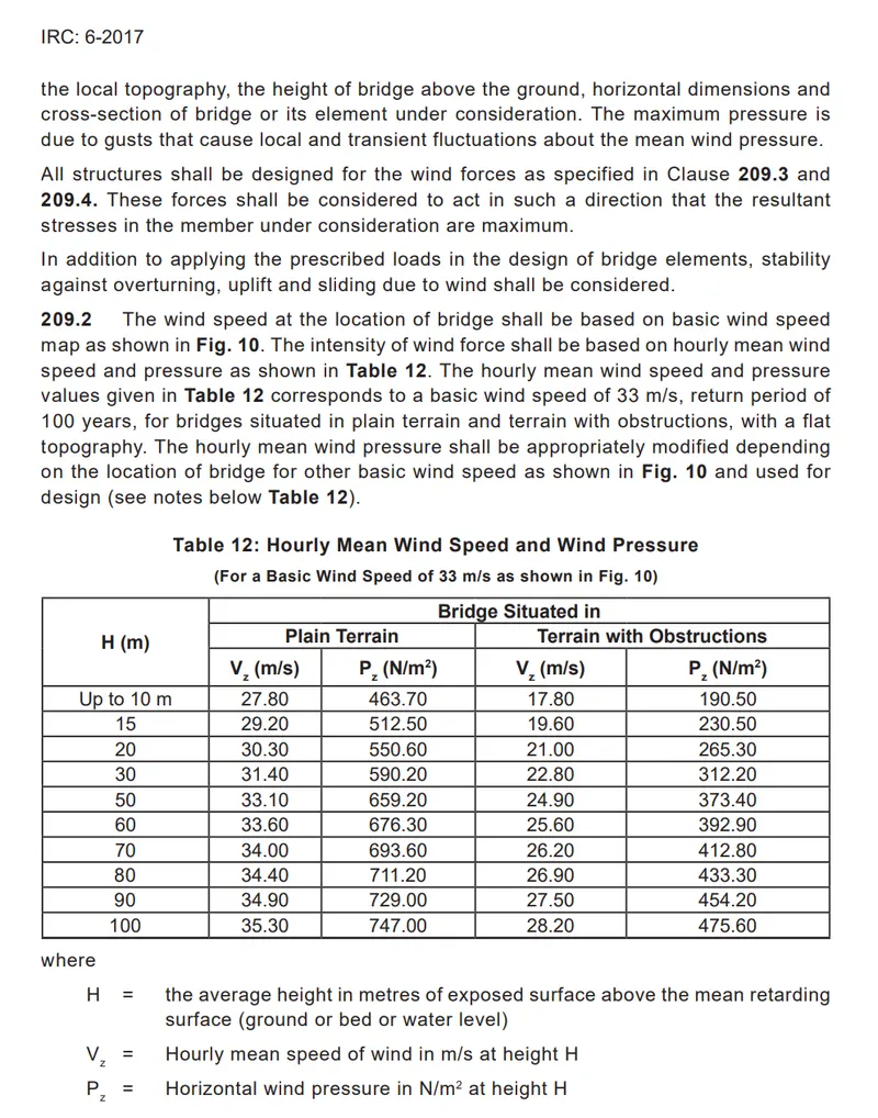
The table 12 of the IRC-6 gives the design pressures for different heights for basic wind speed of 33m/s and for a return period of 100 years.
Pz = 0.6 Vz^2
up to 33^2 - 463.70
44^2 - x
x =44^2x463.70/33^2
x= 824.355N/m^2 for the wind speed of 44m/s
When we compare the values obtained from IS 875 part-3 and IRC - 6 the value obtained from IS 875 is more , considering the highest value for the design.
**********************************************************************************************************
The following is the procedure followed in the Staddd Model for the analysis
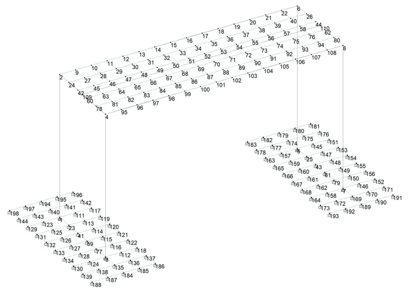
The Node and Element number of the Model.
The Node numbering of the model
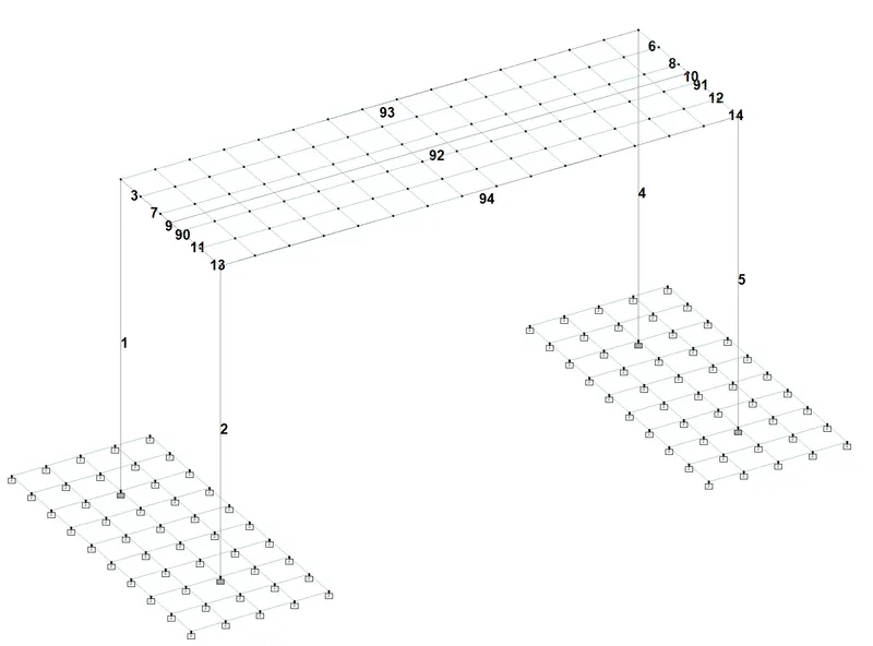
The Beam Numbering of the Model.
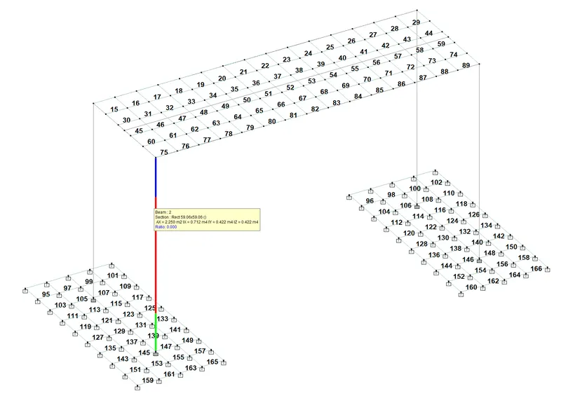
The Plate numbering of the Model.
The support System
The foundation is assumed as a plate mat, The details are given below.
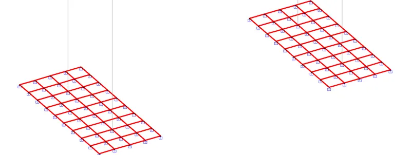
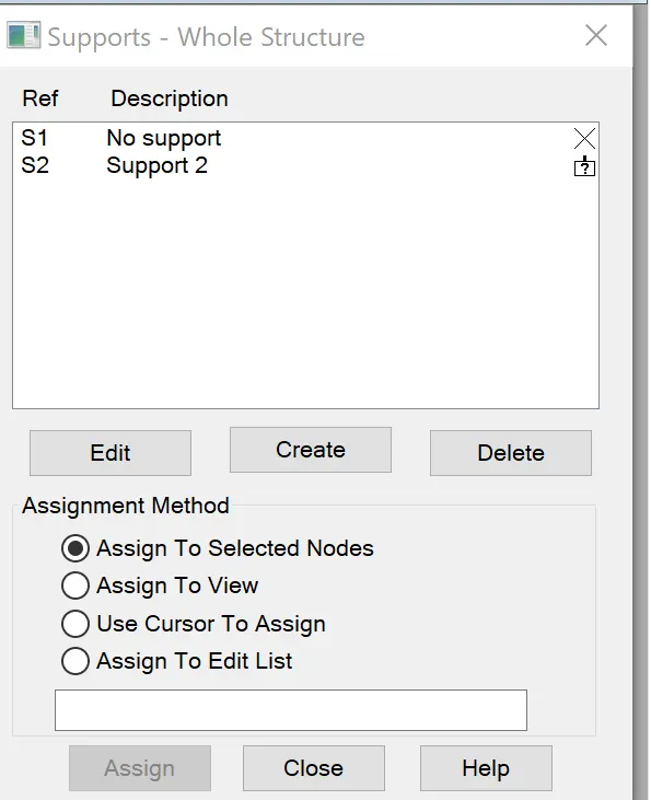
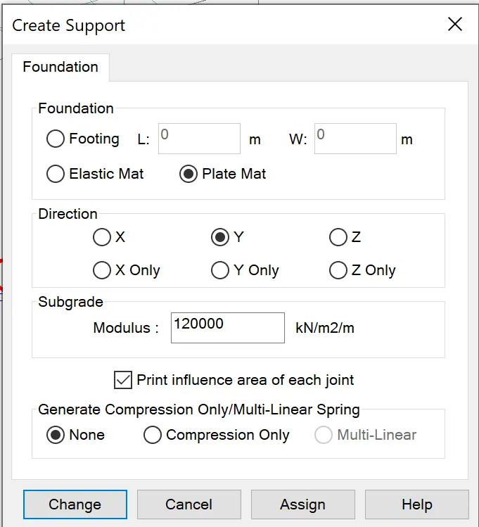
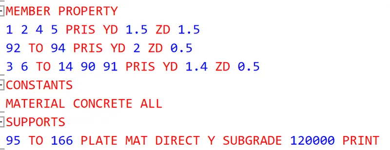
From the command file the following propeties , specification and support are given
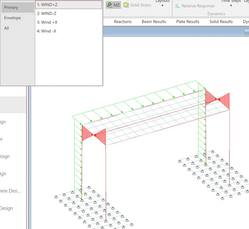
Wind loading diagram +Z direction
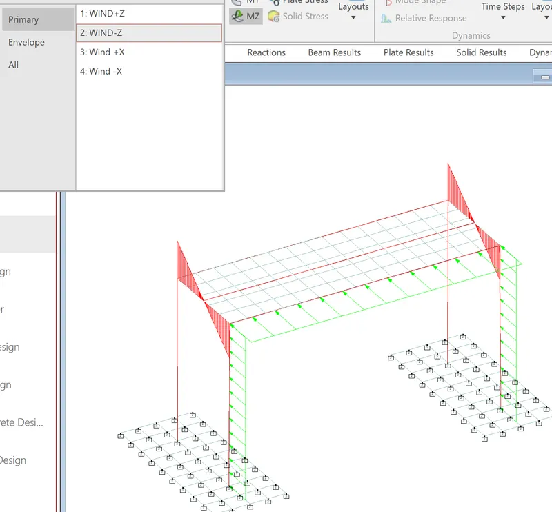
Wind loading diagram -Z direction
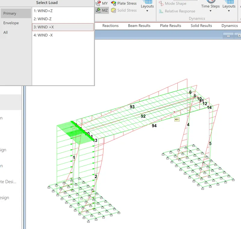
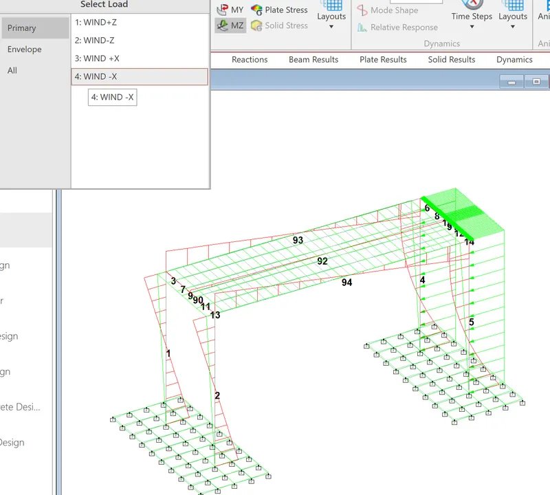
Loading in -X direction
Results
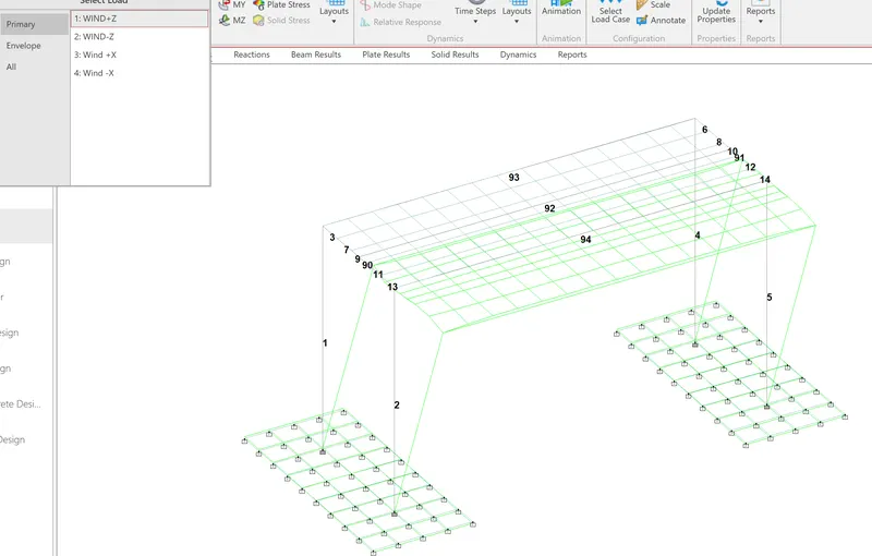
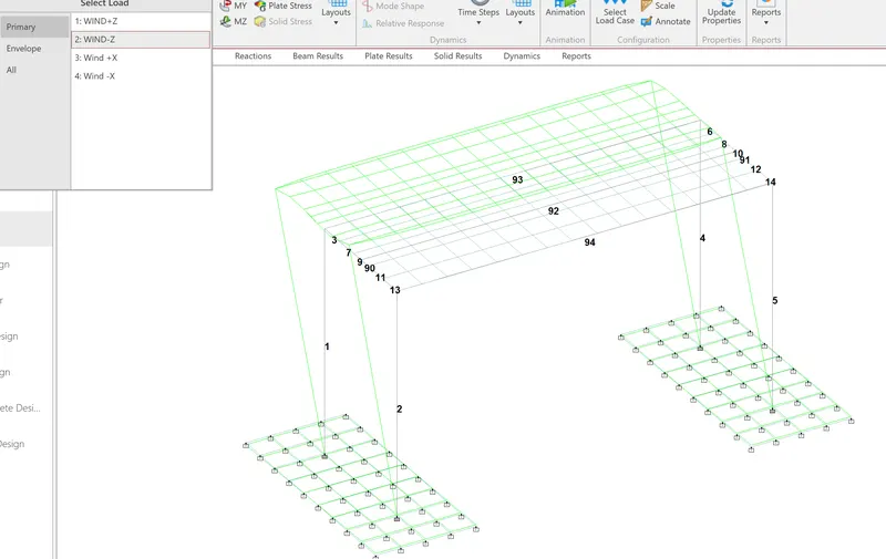
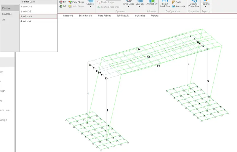
Displacement
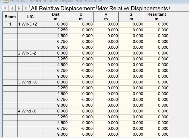
Deflection in +z direction
Deflection in - Z direction
Deflection in + X direction
Deflection in -X direction
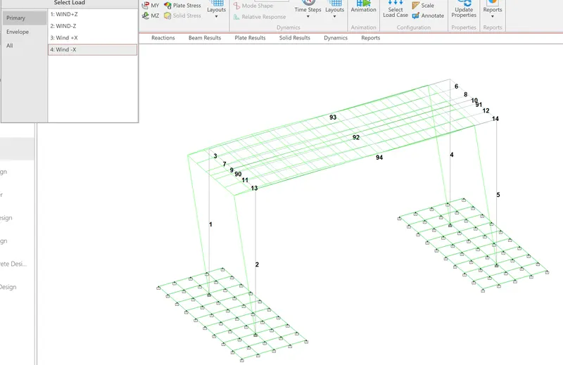
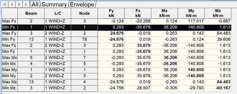
For Pier-1, the following table shows the results
The results are selected from Results tab- reports.
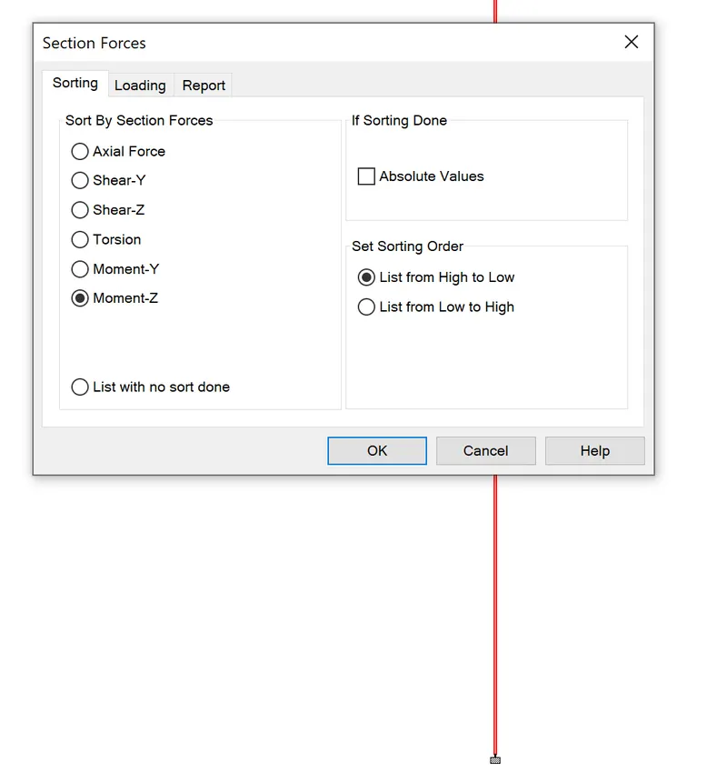
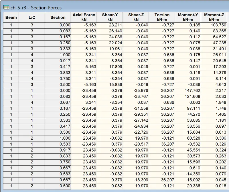
For the same Beam -1 , the My values are shown below.
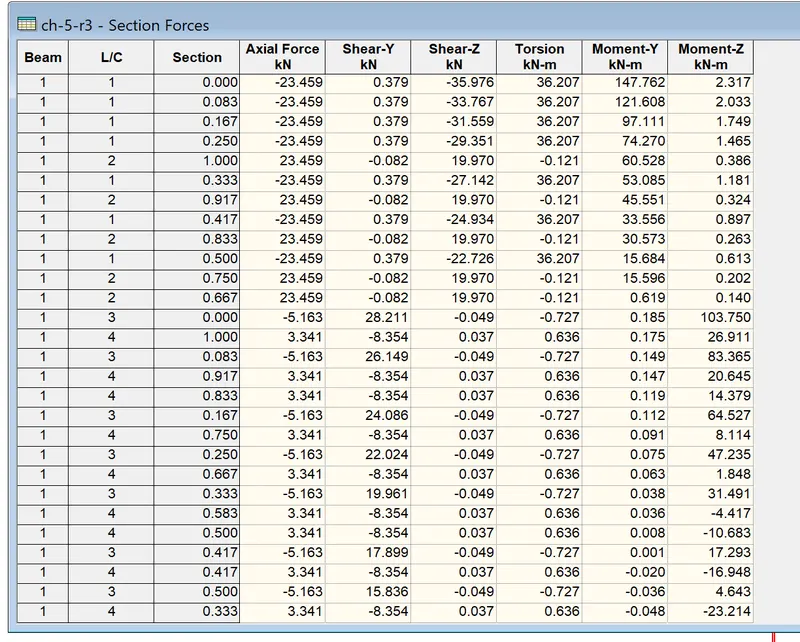
Similarly for Shear- X, Shear -Y values can alos be selected and viewed.
*****************************************************************************************************************
On double clicking the beam element we get the following
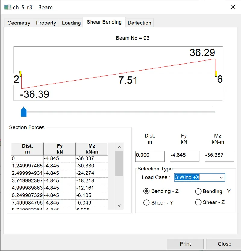
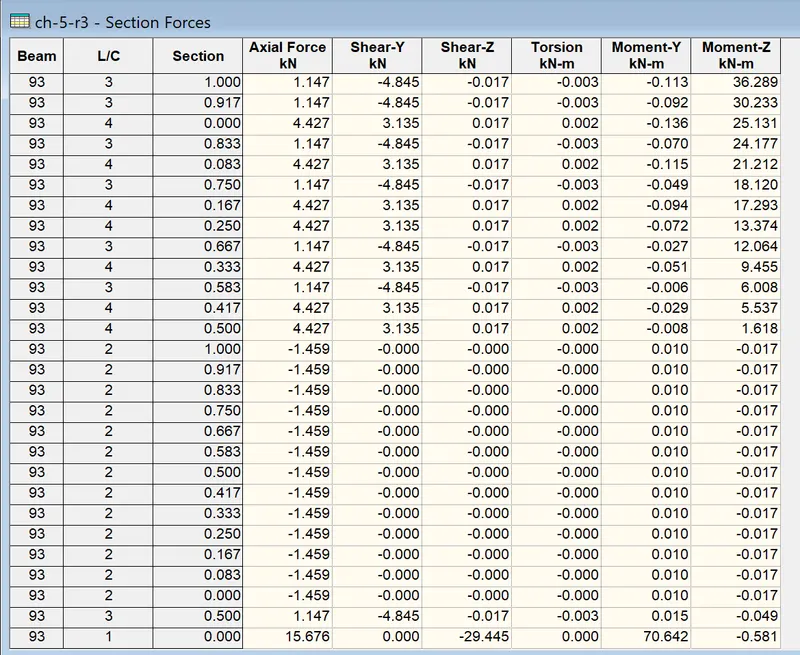
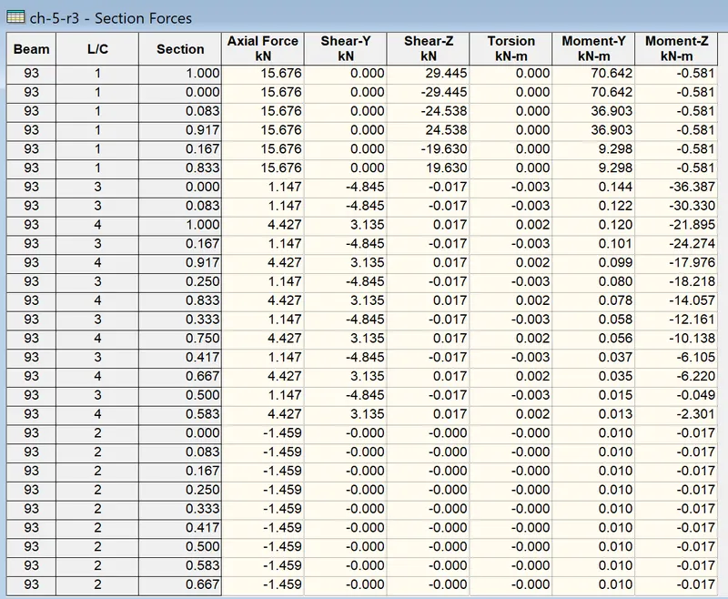
Similarly by using result tab- reports we can get the same results as shown from the table obtained from reports.
****************************************************************************************
The results on the foundation
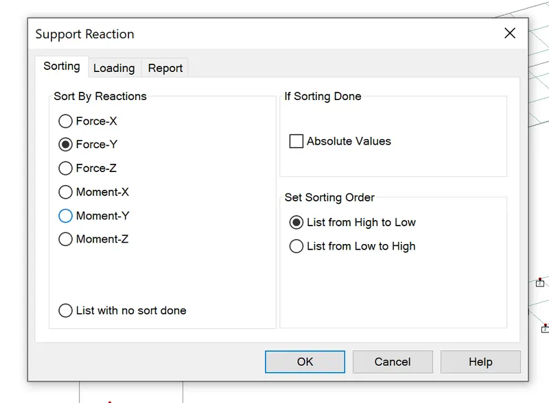
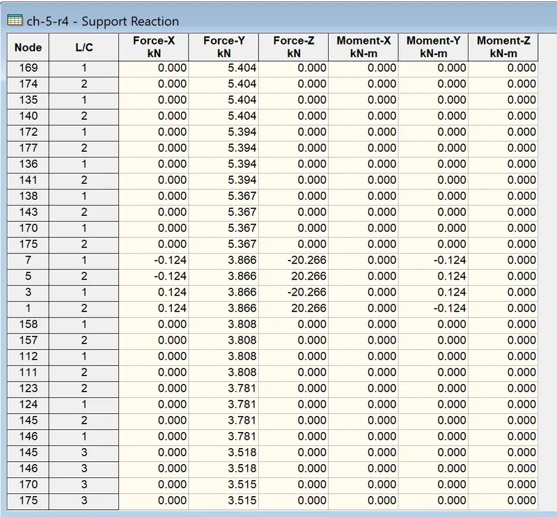
Here at the 169 node and load case - 1 has aximum reaction.
The MZ diagram for load case-1