Creation of Column Schedule and Drawing Template using AutoCad
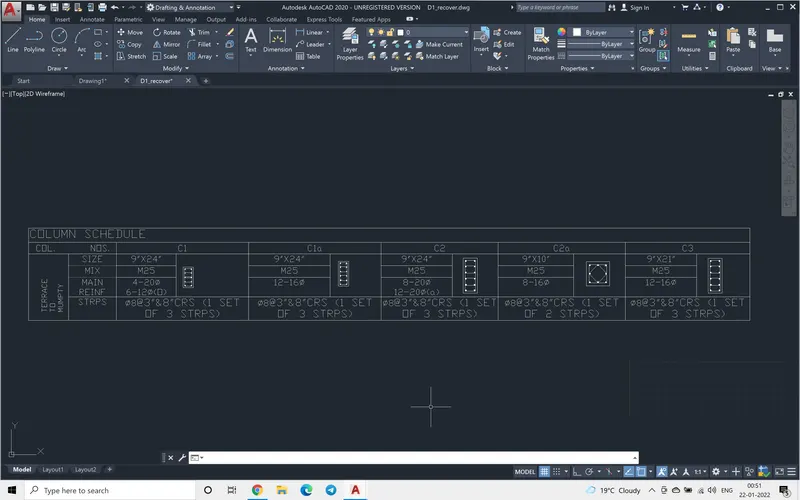
AIM: To produce a column schedule using table command .
INTRODUCTION: The following table can be done using Excel sheet or by using table command in Autocad.After arriving at number of coulmn and rows, the desired format as shown in the following table can be achieved by formatting table, i.e by merging cell, by aligning the text.The special characters like diameter symbol are obtained by typing %%C.
PROCEDURE:
Step 1.
At the command prompt typing table.
selecting the following from the table, the title, header, data, number of column =12, number of rows =6, in text selecting the font as txt
Step 2.
The special characters like dia symbol are typed using %%c.
Step 3.
The column drawing are drawn in the position
The following table is drawn
****************************************************************************************************
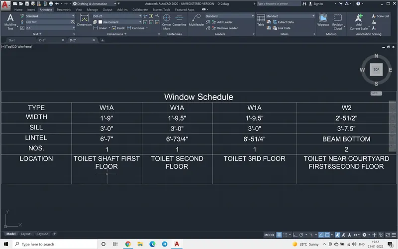
AIM: To produce a Window schedule using table command .
INTRODUCTION: The following table can be done using Excel sheet or by using table command in Autocad.After arriving at number of coulmn and rows, the desired format as shown in the following table can be achieved by formatting table by right clicking on the selected cell and choosing the formatting to be done.
PROCEDURE:
Step 1.
At the command prompt typing table.
selecting the following from the table, the title, header, data, number of column =5, number of rows =7, in text selecting the font as verdana. The last two rows I have merged the cells individually.
Step 2.
The justification of the text is done by right clicking and choosing the alignement. If the alignment is uniform through out the table cells then we can do that in one shot by editing the table command.
The following table is drawn
******************************************************************************************************
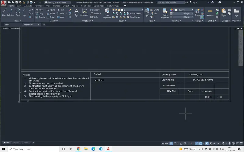
AIM: To produce a drawing template of title block.
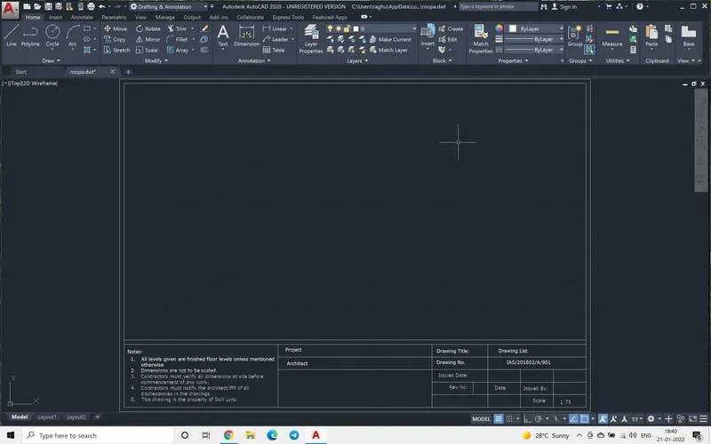
INTRODUCTION: The following template is prepared for A3 size sheet (420x297). The drawing which is drawn is saved in template format (.dwt).This template can be reused when ever A3 size drawings needs to be printed.
PROCEDURE:
Step 1.
At the command prompt typing units
checking for decimal, precision 0.0
Step 2.
Setting the Limits
command prompt LIMMax (420, 297)
Step 3.
Command prompt: rectangle
specifing 0,0 as lower corner
Upper point as 420,297
Step 4.
command prompt: offset command.
giving the required offet dimension
Step 4
command: explode, selecting the inner rectangle.
Step 5
Using the horizontal line of the inner rectangle, which was exploded in offset command to arrive at the title block height.
Step 6
using divide commandon the horizontal line, the title block which was a single rectangle , is now divided in to 3 equal parts.
further the divisions are carried by line command.
Step -7
The text is entered as shown in the table below.
The following template or the title block is drawn.
******************************************************************************************************************
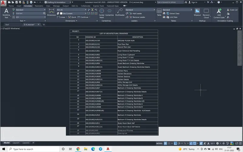
AIM: To produce a drawing list using table command .
INTRODUCTION: The following table can be done using Excel sheet or by using table command in Autocad.After arriving at number of coulmn and rows, the desired format as shown in the following table can be achieved by formatting table, i.e by merging cell, by aligning the text.
PROCEDURE:
Step 1.
At the command prompt typing table.
selecting the following from the table, the title, header, data, number of column =3, number of rows =29, in text selecting the font as verdana
Step 2.
The required text is entered and justification is done for data it is top left, for title it is centre left and for header it is top centre.
The following table is drawn
***************************************************************************************************
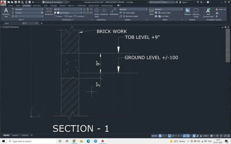
AIM: To produce the column section drawing as shown.
INTRODUCTION: The following section is drawn using the following commands, line, offset, breakline, hatch, quickleader and multileader commands.
PROCEDURE:
Step 1.
At the command prompt typing line.
As the dimensions were not shown, a line of random length was drawn.
Step 2.
At command prompt, using offst command to offset the line.
Step 3.
At command prompt breakline command is used.
picking the first point, second point and the position of the break. If the break line is not visible, then typing size we can increase the break dimension.
Step 4:
Using Hatch command, the required hatch shapes are choosen.for concret there is special concrete hatch option.
Step 5:
Using multileader command the levels are mentioned.
using quick leader and the mtext the brickwork is shown
Step 6:
The dimension are measured and the dimension is edited to required values.
The following section is drawn.